Analysis of the Production System at
ABB Combustion Engineering Newington Operations
by
Rhonda L. Patton
B.S., Mechanical Engineering (1999) Massachusetts Institute of Technology
Submitted to the Department of Mechanical Engineering in Partial Fulfillment of the Requirements for the Degree of
Master of Science in Mechanical Engineering at the
Massachusetts Institute of Technology June 2000
0 2000 Rhonda L. Patton All rights reserved
The author hereby grants to MIT permission to reproduce and to
distribute publicly paper and electronic copies of this thesis document in whole or in part.
Signature of A uthor...
Department of Mechanical Engineering May 5> 2000
C ertified by ...
David S. Cochran Assistant Professor of Mechanical Engineering
A ccepted by ...
Am A. )omn
Chairman, Committee on Graduate Students MASSACHUSETTS INSTITUTE
OF TECHNOLOGY
Analysis of the Production System at
ABB Combustion Engineering Newington Operations
by
Rhonda L. Patton
Submitted to the Department of Mechanical Engineering on May 5, 2000 in partial fulfillment of the requirements for the Degree of Master of Science in
Mechanical Engineering
ABSTRACT
ABB Combustion Engineering Nuclear Power Newington Operations is a manufacturer of industrial and nuclear equipment located in Newington, New Hampshire. This thesis
examines the current production system at ABB and applies the Manufacturing System Design Decomposition, developed by Professor David Cochran, Professor Paulo Lima, and the students of the Production System Design Laboratory at MIT, to begin planning the transition to a lean manufacturing system for the production of spent fuel dry storage canisters. Lean manufacturing is based on the philosophies of the Toyota Production System, developed by Taiichi Ohno. Just-in-time and autonomation are the two main pillars of TPS. The ultimate goal of TPS is to eliminate all waste in the system, which is accomplished by setting up cells, which reduce travel distance, producing exactly the amount needed when needed, which minimizes inventory and prevents overproduction, and eliminates all non-value adding activities.
The main obstacles that ABB must deal with in transitioning to a lean manufacturing system are resistance to change, the challenge of combining a cellular manufacturing system with a project shop manufacturing system, and working with the quality regulations set forth in the ASME Boiler and Pressure Vessel Code. ABB Newington has been producing industrial and nuclear equipment for over 40 years now. Many of the employees at ABB have been working there for a significant length of time. For these reasons, changing the philosophy of production is going to be difficult. Some of the components of the spent fuel canisters are extremely large
and can't be moved easily. As a result, the production system at ABB will have to combine typical cellular manufacturing methods with project shop methods, where some of the
components remain stationary and other parts come to them. Lastly, ABB must deal with the fact that the ASME Code prohibits inspection of parts by anyone that performed or directly supervised the work being inspected. Thus, self inspection as part of the cell work loop is impossible. ABB must be creative in dealing with this challenge and try to find ways to compromise between the stipulated inspection requirements and the ideals of TPS.
Thesis Supervisor: David S. Cochran
TABLE OF CONTENTS
TABLE OF CONTENTS ... 5
L IST O FIG U R E S ... 6
LIST O F T A B LE S ... 6
ACKNOWLEDGEMENTS ... 7
1.0 Introduction and General Background Information...9
1.1 ABB Combustion Engineering Nuclear Power Newington Operation... 9
1.2 Spent Fuel Dry Storage Canister Production... 10
1.3 O u tlin e ... 1 1 2.0 "Lean" Manufacturing... 12
2.1 Toyota Production System... 12
2.2 Manufacturing System Design Decomposition... 14
2.2.1 A xiom atic D esign... 14
2.2.2 Manufacturing System Design Decomposition...15
2 .3 In spection ... 16
2.3.1 Statistical Process Control and Acceptable Quality Levels...17
2.3.2 Judgem ent Inspection...22
2.3.3 Inform ative Inspection... . 22
3.0 Existing Conditions and Project Goals... 24
3.1 C urrent Plant L ayout...24
3.2 Flow of Parts and Information...26
3.3 Scrap, Non-conformances, and Corrective Action...28
3 .4 Inspection ... 29
3.5 W orker A ctivities... 30
3 .6 S chedulin g ... 32
3.7 Project G oals... 33
4.0 MSD Decomposition Applied to ABB Newington... 34
4.1 Top Three Levels of PSD Decomposition... 34
4 .2 Q u ality ... 37
4.3 Identifying and Resolving Problems... 40
4.4 Predictable Output...42
4.5 D elay R eduction... 45
4 .5 .1 T ak t T im e ... 4 7 4.5.2 F loor L ayout... . .. 49
4.5.3 Sam ple M achining C ell... 51
4 .5 .4 In spection ... . . 55 4 .6 D irect L ab or... 57 4 .7 Indirect L abor...59 5.0 Concluding Comments... 60 5.1 S um m ary ... 60 5 .2 O b stacles... 60 5.3 T he N ext Steps... 6 1 5.4 F inal C om m ent... 63 R E FE R E N C E S ... 65 A P P E N D IX A ... 66
Figure 2-1: Figure 2-2: Figure 2-3: Figure 2-4: Figure 2-5: Figure 3-1: Figure 3-2: Figure 3-3: Figure 3-4: Figure 3-5: Figure 3-6:
Type I and Type II errors of the Decision Making process... Sample travel distances of selected parts... Part demand in sample machining cell... Cycles times of each part at each machine in the sample cell... Improvements resulting from formation of sample machining cell...
20 28 52 53 54 LIST OF FIGURES
O verall layout of the M SD D ... 16
Normal distribution curve with p = 0, a& = 1... 18
Graphical representation of (x-error... 19
Graphical representation of
B-error...
20Confidence intervals of a standard normal distribution... 21
Current layout of the Light Manufacturing Building... 25
Current layout of the Heavy Manufacturing Building... 25
Histogram of inspection times... 30
Pareto chart of worker activities during a random 2-hour time slot...31
Percentage of total worker hours spent on each operation/activity during a random 2-hour tim e slot... 31
Pie chart of value adding, non-value adding but necessary, and waste during a random 2-hour time slot... 32
Levels I, II, and III of the MSDD...35
"Quality" branch of the MSDD... 38
"Identifying and Resolving Problems" branch of the MSDD... 41
"Predictable Output" branch of the MSDD... 43
"Delay Reduction" branch of the MSDD... 46
Typical cellular manufacturing layout of the ship building industry... 49
Possible linked-cell layout for production of canisters at ABB... 50
Machine-part matrix used to establish part families... 52
Possible layout for the sample machining cell... 54
"Direct Labor" branch of the MSDD... 57
"Indirect Labor" branch of the MSDD... 59
Figure Figure Figure Figure Figure Figure Figure Figure Figure Figure Figure 4-1: 4-2: 4-3: 4-4: 4-5: 4-6: 4-7: 4-8: 4-9: 4-10: 4-11: LIST OF TABLES Table Table Table Table Table 2-1: 3-1: 4-1: 4-2: 4-3:
ACKNOWLEDGEMENTS
I would like to thank Professor David Cochran for providing guidance and inspiration for
this thesis. I would also like to thank everyone at ABB Combustion Engineering in Newington, New Hampshire for their constant support and assistance. I certainly couldn't have done this thesis without their help.
1.0 INTRODUCTION AND GENERAL BACKGROUND INFORMATION
This thesis presents a methodology that can be used as a guideline in the transformation of a traditional job shop plant to a lean manufacturing plant in the nuclear industry and is based on studies done during an internship at ABB Combustion Engineering Nuclear Power
(ABB-CENP), Newington Operations (Newington) in Newington, New Hampshire. The internship
project was primarily a "feasibility study" to examine the major roadblocks that ABB would have to confront in developing a lean manufacturing system and devise a plan to deal with these major issues. While the details of the system pertain particularly to ABB-CENP Newington Operations, the general philosophies and methodologies can be applied to many other
manufacturing plants, particularly those in the nuclear industry or other highly regulated industries.
In particular, the issue of quality control and quality assurance is largely addressed in this thesis. The requirements for quality inspection imposed upon ABB (and the nuclear industry, in general) by the U.S. government are in direct conflict with the main principles of cellular
manufacturing. The work done in this thesis examines that conflict and addresses possible compromise.
1.1 ABB Combustion Engineering Nuclear Power Newington Operations
ABB-CENP Newington Operations is a manufacturer of industrial and nuclear
equipment. For more than 40 years, Newington has been manufacturing high precision stainless steel and high alloy components for the nuclear energy industry. Newington manufactures the reactor vessel internals (RVIs), which provide a support structure for the core and provide a flow path within the reactor vessel; the control element drive mechanisms (CEDMs), which are
electromechanical devices that insert and withdraw the control element assembly; and the reactor coolant pumps (RCPs), four pumps that circulate water through the reactor coolant system, each with a rated flow from 85,000 to 120,000 gallons per minutes at 8,000 to 12,000 horsepower.
Newington Operations is part of Nuclear Systems, a division of ABB Combustion Engineering Nuclear Power, Inc.. Newington Operations employs 144 employees, 95 of which are hourly employees.
The facilities in Newington consist of two large manufacturing warehouses, one known as the "light manufacturing" building and the other known as the "heavy manufacturing" building. The light manufacturing building runs two shifts, while the heavy manufacturing
building runs three shifts. There is also a building that houses quality assurance, including all retained quality assurance records, and another building that houses design engineering, human resources, production control, and purchasing.
1.2 Spent Fuel Dry Storage Canister Production
In December of 1998, ABB-CENP Nuclear Systems won a contract to build spent fuel dry storage canisters. This contract is the first of many contracts that ABB expects to win over the next few years.
Newington Operations is simply the fabricator of these canisters. External firms did the design. There are three basic designs to the canisters that ABB may build over the next few years, that are all similar in basic structure but vary in the amount of machining, welding, and assembling involved.
During this internship period, production of the first canister contract was underway. However, a major design problem was discovered partway through the internship period and
production of the canisters was halted. ABB then began assisting in an R&D effort to correct the problem. The projected restart is 2002, which is when rework on the partially constructed
canisters will be done, as well as complete production of additional canisters for the contract. Fabrication of a second type of canister has already started at ABB, though no finished products are scheduled to ship until July 2000.
Thus, this thesis focuses on the general state of the production system in Newington with examples taken from canister production.
1.3 Outline
Chapter 2 gives a brief description of the Toyota Production System (TPS) and the Manufacturing System Design Decomposition (MSDD), which are used to analyze the
production system at ABB and suggest improvements to the system. This chapter also details the inspection philosophies of mass production and TPS.
The current state of the production system at ABB-CE Newington Operations is described in Chapter 3. The goals of this project are also laid out.
Chapter 4 is the heart of this thesis. The MSDD is used as a tool to analyze the
production system at ABB and determine feasible ways to improve the system. Certain sections of the MSDD are emphasized over others due to their pertinence to ABB's production system.
Finally, in Chapter 5, comments are made regarding inspection at ABB and the regulations infringed upon the industry. Chapter 5 also includes a summary of the analysis presented in this thesis and recommends the next steps for ABB to take.
2.0 "LEAN" MANUFACTURING
This chapter provides a brief history and overview of the Toyota Production System, as well as describes the Production System Design Decomposition Framework that was used to analyze the current production system at ABB. Finally, a detailed look at the inspection procedures and philosophies of mass versus "lean" production is presented.
2.1 Toyota Production System
Lean manufacturing, the Toyota Production System (TPS), and Just-in-Time manufacturing are all synonyms for the production system developed by Taiichi Ohno.
Following World War II, when Japan was in a state of rebuilding and resources were scarce, the President of the Toyota Motor Company, Kiichiro Toyoda, said, "Catch up with America in three years. Otherwise, the automobile industry of Japan will not survive" [Ohno, 1988]. Ohno, who worked for Toyota, looked at the mass production systems in existence in America at the time to try to find ways to keep his company in business. Ohno had once been told that the work force ratio between Japan and America was 1-to-9 [Ohno, 1988]. How could this be? Ohno knew that there was no way that American workers could actually exerted ten times more physical effort than Japanese workers. This was when he realized that there was simply too much waste in the Japanese system that was getting in the way of productivity.
In Japan, demand for automobiles was not as high as in America and Toyota did not have as many resources as the American companies. As a result, Ohno created a system based on two pillars: just-in-time and autonomation (automation with a human touch). Just-in-time refers to the method of making only what is needed, when it is needed. This meant that Toyota could keep a minimal amount of inventory and work-in-process (WIP), which would reduce their costs.
Autonomation is the use of machines "with a human touch" [Ohno, 1988]. That is, machines that can detect defects autonomously. When a defect is detected, the machine stops and cannot continue until the source of the problem is corrected.
The ultimate goal of TPS is to reduce the amount of time between when the customer's order is taken and when the company receives the cash for the product. This time reduction is
accomplished by eliminating waste. The seven wastes as defined by TPS include [Ohno, 1988]:
" waste of overproduction
" waste of time on hand (waiting on machines) " waste in transportation
" waste of processing itself
" waste of stock on hand (inventory)
* waste of movement
" waste of making defective products
Elimination of these wastes can improve system efficiency and reduce costs.
The main working unit of TPS is the cell. In mass production systems, all machines of the same type are in one department, which requires parts to criss-cross through the shop from one operation to another. Ohno realized that if he set up a sequence of machines in the proper order of operations, the parts could quickly travel, one part at a time (referred to as single-piece flow), through the U-shaped or L-shaped cell, drastically reducing the distance that the parts had to travel. This layout also allowed workers to operate multiple machines at once. The worker could set-up a part in a particular machine, hit a switch to make the machine begin, and while that machine was running, move onto the next machine in the cell continuing in a similar manner. By creating these "work loops," production efficiency drastically improved over the
"one operator, one process" methods of mass production.
To keep inventory levels low and assure smooth flow of parts through the cells, balanced production and leveled production were implemented. In balanced production, all operations or
cells produce at the same cycle time, which is less than or equal to the takt time [Cochran, 1999,
2.82/2.812 class notes]. Takt time is the pace at which parts should be produced to meet
customer demand, and is defined as the available time per shift divided by the average demand per shift. Leveled production means that all operations make the quantity and mix of products demanded by the final customer within a given time interval [Cochran, 1999, 2.82/2.812 class notes]. Thus, instead of producing long runs of the same type of parts, a variety of parts are produced in smaller runs. To achieve this objective, however, changeover times had to be drastically reduced, which was accomplished through single-minute exchange of dies (SMED) [Shingo, 1989]. Takt time and leveling of production should be recalculated and adjusted on a regular basis. This could be weekly, monthly, or annually, depending on the rate of change of customer demand.
The method used to enforce just-in-time is called kanban, which is the Japanese word for "card." A kanban is typically a small card in a protective envelope that contains information about pickup, transfer, and production [Ohno, 1988]. The use of kanban prevents
overproduction or production of the wrong parts.
The bottom line of Ohno's system is constant improvement. In taking a look around the plant, small increments of progress can always be made to help get the product to the customer faster and reduce waste. The Japanese word used to describe this philosophy is "kaizen."
2.2 Manufacturing System Design Decomposition
2.2.1 Axiomatic Design
Axiomatic Design provides a means to translate customer needs into specific design implementations through mapping the Functional Requirements (FRs) and Design Parameters
(DPs) [Suh, 1990]. The FRs, in the functional domain, are determined directly from the needs of the customer and detail specific requirements that the design must accomplish. The DPs are in the physical domain, and specify the physical implementations set forth by the FRs. Put simply, the FRs state what to accomplish and the DPs state how to accomplish it.
A top-level functional requirement is established, with its corresponding design
parameter. More functional requirements are derived from the top level DP, which each have their appropriate DPs. This breakdown continues until the bottom level DPs are feasible, implementable solutions to the desired goals. The mapping of FRs and DPs must follow two design axioms [Suh, 1990]:
Axiomi: The Independence Axiom
Maintain the independence of functional requirements (FRs). Axiom 2: The Information Axiom
Minimize the information content.
2.2.2 Manufacturing System Design Decomposition
Professor David Cochran, Professor Paulo Lima, and the students of the Production System Design Laboratory at MIT have developed a Design Decomposition, using the method of axiomatic design, for a production system. The Manufacturing System Design Decomposition
(MSDD) can be used to closely examine "lean" production systems. A better understanding of
what needs to be achieved in order to attain a "lean" production system and how to achieve it can be achieved by "zig-zagging" along the path mapped out by the FRs and DPs of the
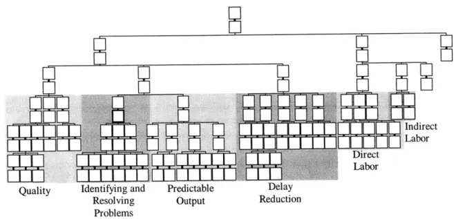
The overall layout of the MSDD is shown in Figure 2-1. The MSD Decomposition can be divided into six sections: (1) Quality, (2) Identifying and Resolving Problems, (3) Predictable Output, (4) Delay Reduction, (5) Direct Labor, and (6) Indirect Labor. The sections are detailed in Chapter 4.
Indirect Labor Direct
. . . .. ... L abor
Quality Identifying and Predictable Delay
Resolving Output Reduction
Problems
Figure 2-1: Overall layout of the MSD Decomposition with the six branches labeled.
2.3 Inspection
Because this thesis emphasizes the problems with inspection found at ABB and in the nuclear industry, in general, we must first examine the differences between inspection methods at mass production plants and job shops versus the inspection methods in the Toyota Production
2.3.1 Statistical Process Control (SPC) and Acceptable Quality Levels (AQL)
In the 1920s, at Bell Telephone Laboratories, statistical process control (SPC) began [DeVor et al., 1992]. SPC uses statistics and probability concepts to draw conclusions about a population after examining a small amount of data. These conclusions, however, cannot be
stated with absolute certainty. The introduction of uncertainty into the picture causes some problems. Typically, sample inspection involves two particular monitoring tools, acceptance sampling and/or control charts.
Sampling is done when it is either too costly, too difficult, or impossible to inspect all the parts. For example, the cost associated with the time needed to inspect every part may be too much, inspection of the parts may be destructive, or not all of the parts may yet to have been produced.
In acceptance sampling, a maximum amount of defective parts is allowed to be produced for the lot to be considered satisfactory. This "acceptable quality level" (AQL) means that some defects are accepted in each lot sampled. In today's competitive world of high-quality, no defects are acceptable.
Control charts are used to track the mean and variability of a process. Key characteristics of the parts produced are, again, sampled, and their mean value is plotted on an X-average chart, while their range or variability is plotted on an R chart or cy chart, respectively. These charts are
known as Shewhart Control Charts, named after their founder, W.A. Shewhart, who worked at Bell Labs in the 1920's. Upper and lower control limits are set on each chart and the
characteristics of each sample are plotted. The plot is examined for trends or "out-of-control" data points, which are then evaluated for their probable cause. The theory behind control charts is that there are two types of causes of variation. "Chance" causes are natural causes that are
inherent in the process. They are extremely difficult to isolate, and, frankly, are usually too small to really care about. Chance causes result from inherent variability in, for example,
material properties and measurement error. Control charts are mainly used to detect the presence of "assignable" causes. Assignable causes are events that alter the accuracy and/or precision of the process. Examples of assignable causes are environmental changes (temperature fluctuations in the factory), tool wear, noise resulting from excessive machine vibrations, and intentional adjustments to the machine's settings. When assignable causes are detected, they must be evaluated and fixed to bring the process under control.
Shewhart developed this method of charting the mean and variability of key
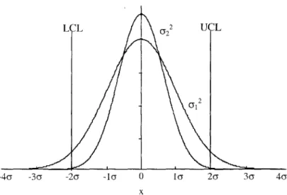
characteristics of processes based on the fact that natural sample statistics will be "normally distributed" about its mean value. Figure 2-2 shows a normal distribution with the mean value at zero. The width of the curve is determined by the variability, c2. This figure also shows how the normal distribution curve, when still centered at a mean value of zero, "narrows" when
022 < 7 . The upper and lower control limits, in this case, set at +/-2o, are shown on the chart.
LCL 22 UCL
2
-4y -3c -27 -ic7 0 icy 2cy 3(y 4a
x
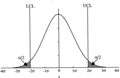
The region under the curve and outside the control limits is called the x-error, also known as a Type I error. A Type I error is defined as "viewing a process as bad, when it is
actually not making defects." cx is known as the "significance of the test." See Figure 2-3.
LCL UCL
W 2 aY2
-4a -3a -2a -la 0 la 2a 3a 4cy
x
Figure 2-3: The area under the normal curve and outside of the control limits is the x-error.
The opposite kind of error that can be made is to "view a process as good, when it is actually making defects." This is known as a Type II error or
P-error.
The value (1-$) is known as the "power of the test." The value ofP
is determined from the area under the curve that is inside the original control limits when a shift in the mean value of the process has occurred. Figure 2-4 depicts the value ofP
for a process whose mean value has shifted over +3a.In a manufacturing setting, either ct-error or 1-error can be minimized, but not both. Minimizing one type of error compromises the other. Table 2-1 illustrates the decision-making (DM) process that results from control charts and Type I and Type II errors [Black, 1991].
L 0
-4a -3cy -2a -la 0
x
la 2a 3a 4a
Figure 2-4: The value of P is equal to the area under the curve of the shifted curve that is within the original control limits.
The sample suggested to the DM that:
The process has not changed.
The process has changed.
The truth was that the DM takes no actions as DM takes action, but nothing
process had not changed. nothing is wrong. can be found to be wrong with
the process; Type I error, DM embarrassed.
DM takes no action, but process making more defects;
Type II error.
DM takes action, finds problem with process. DM
looks good! Table 2-1: Two types of errors can be made during the "Decision Making"
process, Type I and Type II errors.
This type of inspection is known as "judgement inspection." Improving judgement inspection increases the chances of detecting defects (minimizing a-error), but does not actually reduce the number of defects produced.
The truth was that the process had changed.
L Enew
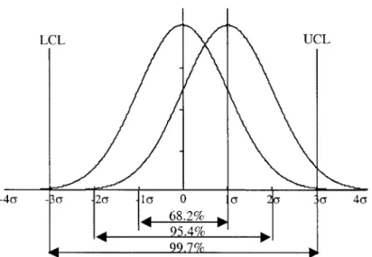
To illustrate Type I and Type II errors numerically, consider a standard normal distribution curve with control limits set at +/-3G from the mean value, which is a typical acceptance range. 99.7% of the measured values will fall inside this acceptance range. (See Figure 2-5.) Thus, the u-error, the probability that a part will be marked defective when it is actually a good part, is 0.3%. In other words, there is a 3/1000 chance that the inspector will think that the process is bad, when it has not changed at all.
LCL UCL
-4cy Ry 2y I CT 0 G ( Cr 4cy
95.4% P
99.7%
Figure 2-5: Confidence intervals of a standard normal distribution.
Now suppose that the mean value shifts over one standard deviation. Instead of the mean value of the process being at zero, the mean value of the process is now at +1. For this shifted standard normal distribution, the area under the shifted curve but still inside the control limits is $ = 97.7%. There is a 97.7% chance that the part will be detected as good, when in reality, the
process has shifted. Due to the fact that sample inspection is being used, instead of 100% inspection, this failure to detect the mean shift allows defective parts to be passed on to the customer (internal or external).
2.3.2 Judgement Inspection
At many companies, inspection is simply defect detection. Improving judgement inspection increases the chances of finding defective parts, but does not actually decrease the number of defective parts.
2.3.3 Informative Inspection
TPS used "informative inspection" methods to detect defects immediately after they are
made, or, better yet, to detect defects at their source, before the defects are actually made. Preventative inspection reduces the amount of waste (defects) produced, which reduces overall costs. While production is often stopped (money lost) while the problem that caused the defect is being corrected, the cost associated with this production loss is less than the cost that would have incurred due to the production of defective parts (cost of scrap or rework). There are three basic types of informative inspection: self inspection and successive inspection, enhance self inspection, and source inspection. All three methods are used in TPS.
In self inspection, each worker inspects his/her own work. A few problems can arise with this type of inspection, though. If the worker misunderstood the work orders, he/she may
unintentionally pass along parts that should have been rejected. Another drawback is that the worker may compromise judgement and knowingly accept parts that are actually defective. To keep inspection within the cell but avoid these problems, the worker can pass along his/her parts to the next worker who inspects them. Successive inspection provides the immediate feedback that self inspection provides, but provides more objectivity.
Another solution to address the conflict of interest that can arise in self inspection is to provide a "mistake-proofing" device, or poka-yoke, to assist in the inspection. Again,
production benefits from the immediate feedback provided by enhanced self-inspection, without the drawbacks of standard self inspection.
The best inspection method is source inspection. By monitoring and controlling the conditions at the source of the operation, defects can be prevented rather than detected. Source inspection can trace the problems "vertically" through the process flow or "horizontally" within an operation.
The most important aspect of the inspection philosophies of TPS is that every part is inspected. 100% inspection assures that defects are not passed to subsequent processes and certainly not to the final customer. All it takes is for one customer to buy one defective product and that company has lost that person's business forever.
3.0 EXISTING CONDITIONS AND PROJECT GOALS
3.1 Current Plant Layout
Production of parts in Newington is split up into two categories: light and heavy manufacturing, which also (generally) corresponds to small and large components. These components are appropriately machined and sub-assembled in the respective light and heavy manufacturing buildings.
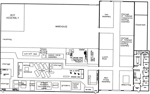
The light manufacturing building is set up mainly in a departmental layout. It also houses a warehouse for the storage of raw stock, as well as partially machined parts and fully-machined parts that are awaiting assembly. A 2-ton boom crane in the light manufacturing building facilitates material handling. See Figure 3-1 for a schematic of the light manufacturing building.
The heavy manufacturing building contains assembly areas, as well as machines needed to produce the large components that Newington makes. These machines are permanent fixtures
in the building. The heavy manufacturing building is divided into two halves, one of which is served by a 30 ton crane with a height of 29 feet, while the other half is served by a 100 ton crane with a height of 70 feet. See Figure 3-2 for a schematic of the heavy manufacturing building. There are also three fork trucks that are used to move material around - small, medium, and large.
In June, at the beginning of the internship, production of the canisters was already underway and plans for a new building (300 feet x 85 feet in area) dedicated to canister
production were being developed. In the meantime, fabrication of the canisters occurred on the existing machines in the shops and wherever floor space could be found.
RCP ASSEMBLY WAREHOUSE receiving Celt Assembly storage of finished components awaiting assembly storage of finished components awaiting assembly Classroom
cut-off s Machine poison strip,..
assembly 0C M"eNE ROOM Lunch
storage wellsaj E
_torage
! tat es TOOL & CUnER
- bands aw
GRNINNG AREA -ai
Crossee
Assembly
storage he ""*i deburrng
___- 11~
grinders--Figure 3-1: Schematic of Light Manufacturing Building. (Note: Drawing not to scale.)
SYS 80 CORE SHROUD The work in this area changes daily LOW BAY (3 GAGE ROOM RCP ASSY POWER SUB-STATION
CNC SYS 80 FAB &
CARLTON 6 G&L FINAL ASSY
RADIAL HBM
, DRILL RCP FINAL ASSY
0 TON) HIGH BAY (100 TON)
______ -CNC
INT DORRIES
FROREIP ASSY VEM
VBM VBM ~7" GRAY HBM CNC STANDTN MAINT. TROOM OFFICES TEST LOOP CRAVEN VBM BLAST/PAINT FACILITY
Figure 3-2: Schematic of the Heavy Manufacturing Building. (Note: Drawing not to scale.)
-3.2 Flow of Parts and Information
Production begins when a project engineer creates a Manufacturing Process Sheet (MPS). The main body of an MPS contains manufacturing and inspection instructions set up in
sequences of operations. The MPS also includes a list of parts/raw materials needed (called the "items checklist"), referenced drawings, weld procedures (which are added later), and inspection procedures. The last page of the MPS is an accounting document called a "J50", which is basically the engineer's best estimate of how long each sequence in the MPS should take, and is used to record the actual hours that each sequence takes.
The MPS then moves to the weld engineer, who adds the specific welding instructions, if any are necessary. Next, the MPS goes to Quality Assurance (QA), who writes up any
Dimensional Inspection Reports (DIR) if they are needed. Manufacturing services receives the MPS next and checks to make sure that all items listed in the items checklist are currently in the warehouse. If they are, then the MPS is ready to be released to the shop floor.
At the same time that the MPS is travelling around getting all its necessary components, the project engineer orders the parts/raw stock needed. When the material arrives in Newington, it must go through the receiving department. Large items that will be machined in the heavy manufacturing building are delivered directly to that building. The parts are received at one of two doors, depending on the weight of the material. (Anything greater than 30 tons must be received at the back entrance, where there is a 100 ton overhead crane. The overhead crane at the front of the building is a 30 ton crane.) All other items are delivered to the light
manufacturing building, which contains the warehouse. (Note: The warehouse only contains material that has been approved for use. Nothing can be kept in the warehouse until it has passed through receiving inspection.) The receiving department checks to make sure that what has been
delivered is truly what was ordered, and also checks to make sure that the material has all necessary certification documents with it. If everything checks out okay, the material is placed in the warehouse until needed. If receiving doesn't approve the shipment, a Non-Conformance Report (NCR) is written stating what the problem is, which then must be verified by QA. The material can either then be returned to the supplier, scrapped, or "repaired" if possible.
At this point, manufacturing services releases the MPS to the shop floor. The items checklist is given to a material handler, who kits the parts and delivers them to the proper work station, which could be in either the light manufacturing building or the heavy manufacturing building. If the machining is happening in the heavy manufacturing building, the items checklist page is usually given to a material handler a day or so in advance of when the parts are actually needed. In the light manufacturing building, if the MPS is currently on the shop floor, it is common for the machinist to walk over to the warehouse, himself, and fill out a "material withdrawal request" to get the material that he needs, rather than go through the shop foreman again. The machinist then begins working.
After the first part is machined, it must be inspected by Quality Control (QC). To do this, the machinist must go to his immediate supervisor (the shop foreman) and tell the foreman that he needs an inspector for a first piece inspection. The foreman then fills out an Inspection Service Request (ISR), which he usually then brings directly to a QC inspector. Inspection generally happens on a first come, first serve basis, so if an inspector is currently free, he performs the first piece inspection. Otherwise, the machinist must wait for a few minutes until an inspector is available. If QC approves the part, the machinist can then continue machining the remaining parts for that particular sequence of the MPS. Sometimes first piece inspection will happen after a few sequences of the MPS have been performed, which then allows the machinist
to perform all of those operations on the remaining pieces. Other times, first piece inspection happens after each individual sequence of the MPS. The project engineer that wrote the MPS determines which of the above procedures to follow.
When the machinist has finished machining all the parts, a QC inspector is needed, again, for final inspection, which can be either 100% inspection or sample inspection, depending on the type and number of the parts. At this point, typically, the machinist will move on to another job, and the ISR will be dropped off in the QC "in-box" and tended to the next day or at the first convenience. If necessary, certain inspection requests can be prioritized over others if the job is in high demand.
The above procedures hold true for assembly, also.
Parts travel all over the shop in Newington. They also travel a good deal between the light manufacturing and heavy manufacturing buildings. Below is a table of a few selected
canister parts and the distances that those parts traveled in the current production system at ABB.
Part Name, Number Distance traveled (ft.)
5x2 tube steel arms, P05-001 580
Structural Ed, P04-001 2,196.5
Shield Lid, top plate, P03-001 1,293.6
Shield Lid, bottom plate, P03-003 1,293.6
Shield Lid, P03-001 welded to P03-003 3,009.6
Table 3-1: Sample travel distances of selected parts.
3.3 Scrap, Non-conformances and Corrective Action
To date, there is no numerical record of the level of scrap in Newington. As for non-conformances, ABB keeps a large database detailing the disposition of all non-conformance
reports (NCR). They track failures, defects, operator, and machine work center involved with each non-conformance, as well as all NCRs caused by suppliers.
When an in-process defect is made, the machinist brings it to the attention of the foreman, who then fills out an NCR detailing the defect. In the NCR, the foreman will also describe any corrective action measures that could be taken to prevent such a defect from occurring in the future. The NCR then goes back to the project engineer, who writes another MPS to either repair the damaged parts or produce completely new ones. Hopefully, also, the project engineer uses the "corrective action" suggestion in the NCR and edits the old MPS so as to improve the instructions and prevent the same mistake from happening in the future. At the same time, the machinists usually take notes on the operations that they do and keep track, for themselves, of things that go wrong, why, and how to prevent them in the future. Unfortunately, the machinists do not always refer back to these notes and thus, repeat the same mistake.
3.4 Inspection
As describe in the previous section, inspection happens many times during each MPS. The first sequence of most MPSs is "QI verify items checklist," which simply requires an inspector to verify that the material has been approved for use. QI is needed for first piece inspection, for verification of fit-ups and weld tacks, for dimensional inspection, as well as for inspection of welds.
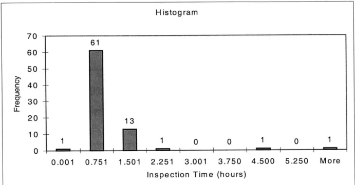
Inspection of parts can take anywhere from a few minutes to a few hours, depending on the type of inspection that is performed, the size of the part being inspected, and the complexity of the part being inspected. The following histogram shows the distribution of inspection times per part for 26 MPSs that were part of the first canister contract. The mean inspection time is
just over half an hour (33 minutes), though the range is from 6 seconds (for a quality inspector to verify the part number of 2816 parts in 3 hours) to 97.5 hours (for the first piece inspection of the
5x2 tube steel arm for the main cross assembly).
Histogram 1 61 13 1 0 0 1 0.001 0.751 1 0 1 .501 2.251 3.001 3.750 4.500 5.250 More
Inspection Time (hours)
Figure 3-3: Histogram of inspection times per part for 26 MPSs of the initial canister contract.
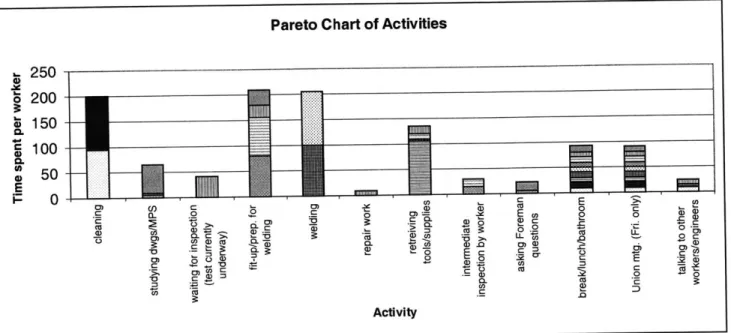
3.5 Worker Activities
ABB Newington is a union shop. Each worker has a specified role and never cross-trains between roles. There are machinists, assemblers, welders, material handlers, and quality
inspectors. Machining and assembly in Newington is highly manual. There is very, very little automation in the plant.
To document typical daily activities, a random 2-hour time slot was chosen and 9
workers were observed during this time slot. The following charts show a breakdown of the time spent on each activity per worker and the percentage of total time (9 workers x 125 minutes of
a) IL 70 60 50 40 30 20 10 0 -- --- - - --- - --
---observation =1125 minutes) spent on each value adding and non-value adding but necessary
operations.
Pareto Chart of Activities
250 S200 -S150 - - *~100-0. 4) 50 0 ) )C)U E/ C ) 0 E 0a a- 0 C . 0 0 CUC - CL a)0C .C ) 4) .9 a) 0)> .0= Ra-)c 0@ a)~- V> LU CU LL tM r- - ) 0) -O 0 c 0 .- 0 C 00 Activity
Figure 3-4: Pareto chart of worker activities during a random 2-hour time slot.
Total Time Spent on Each Operation/Activity
E 40%-P 35% * 30%-,* 25%-'1 20%-15% S10% W. -Y E ( 0 C 0) 0)0 :92 0) 7~ -C. (D .0-V~( 0)0. Operation/Activity
Figure 3-5: Percentage of total worker hours spent on each operation/activity during the same random 2-hour time slot.
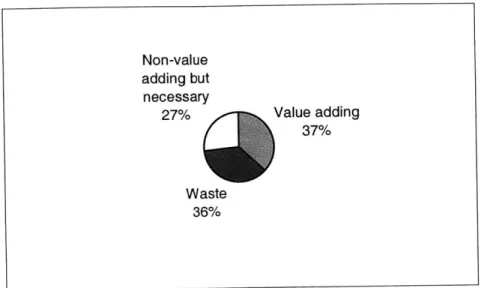
Sorting the above activities into value-adding, waste, and non-value adding but necessary, results in the following breakdown:
Non-value adding but necessary 27% Waste 36% Value adding 37%
Figure 3-6: Pie chart of value adding, non-value adding but necessary, and pure waste observed during the random 2-hour observation period.
3.6 Scheduling
Initial scheduling put together for the bidding process is based on experience for up-front engineering span, long lead material spans, and rough estimates on duration (normally, the latter is a high level look), plus shipping added onto the end. Production scheduling is based on actual engineering/QA tasks scheduled in hours for 40 hours per week per person. Shop work is based on estimated duration for major operations at the sub-MPS level, but not quite at the operation level.
A typical contract at ABB for the System 80 Power Plant components (described briefly
in Section 1.1) takes three years to complete. There is a good amount of play in a 3-year schedule, so ABB doesn't necessarily have to adhere to the nitty-gritty details of their proposed
schedule. There is a lot of opportunity to "catch up" to the schedule and ship the final product(s) on time. For the canisters, however, ABB must adhere to a much stricter schedule. For
example, production of one particular canister contract began in the beginning of March and the first finished canister is expected to ship in July, with another finished product following every two weeks thereafter.
3.7 Project Goals
The purpose of this project is to determine to what extent a cellular manufacturing system is truly feasible at ABB-CENP Newington Operations. The intentions of creating a cellular manufacturing system are to improve the flow of parts through the shop, reduce the amount of inventory and work-in-process (WIP), reduce the amount of floor space taken up by production, and reduce the throughput time and manufacturing lead time.
It is intended that, at the end of this project, ABB can use this thesis as a basis to begin making changes in their manufacturing system. The ideas set forth in this thesis will provide a starting point for ABB to work off of, as well as illustrate the improvements that can be made by making simple changes.
Another goal of this thesis is to address the conflict that arises between the ideals of cellular manufacturing and the necessary "evils" of the nuclear power industry. Specifically, the issue of quality assurance is addressed, as well as the combination of cellular manufacturing and project-shop manufacturing that must take place for the production of these spent fuel canisters. Chapters 4 and 5 explore these issues deeper.
4.0 MSD DECOMPOSITION APPPLIED TO ABB NEWINGTON
The main goal of this thesis is to analyze the current production system at ABB in order to systematically improve the system as a whole. In Chapter 3, the current situation at ABB was described. In this chapter, the MSD Decomposition will be detailed branch-by-branch and
applied to the production system at ABB to determine the necessary path that ABB needs to take in order to transform their plant into a "lean" production system. Suggestions are made or examples are given wherever possible to illustrate potential improvements to ABB's system.
As discussed in Chapter 2, the MSD Decomposition is based on axiomatic design and provides a comprehensive approach to designing a lean production system. The ideas of TPS are
encapsulated in the structured MSDD. The MSDD is used in this thesis because it provides a systematic framework for analyzing a production system.
4.1 Top Three Levels of the MSD Decomposition
Levels I, II, and III of the MSD Decomposition are detailed in Figure 4-1. "FR" states the functional requirement, "PM" details the performance measurement, and "DP" lists the
corresponding design parameter.
The functional requirements of these three levels outline the ultimate goals of the system. As a company, ABB wants to maximize the long-term return on investment, which means maximizing sales revenue, minimizing manufacturing costs, and minimizing investment over the production system lifecycle.
To maximize sales revenue, a company must make sure it's producing quality parts, delivering products on time, and meeting the customers' expected lead time. Minimizing
FR112 Deliver products on time PM112 Percentage on-time deliveries FR1I Maximize long-term return on Investment PM1
Return on investment over
system lifecycle
DP1
Manufacturing System Design
FR113 Meet customer expected lead time PM113 Difference between mean throughput FR121 Reduce waste in direct labor PM121 Percentage of operators' time spent on wasted FR122 Reduce waste in indirect labor PM122 Amount of required FR123 Minimize facilities cost PM123 Facilities cost
time and motions and indirect labor
customer's waiting
expected lead timi
DP-111 DP112 DP113 DP121 DP122 DP123
Production Throughput Mean Elimination of Reduction of Reduction of processes time variation throughput non-value indirect labor consumed with minimal reduction time reduction adding manual tasks floor space
variation from tasks
the target
Quality Identifying Predictable Delay Direct Indirect
and Output Reduction Labor Labor
Resolving Problems
Figure 4-1: Levels I, II, and III of the MSD Decomposition.
Level I
FR11
Maximize sales revenue PM11
Sales revenue
Leve II
Level Ill
FR12
Minimize manufacturing costs
PM12 Manufacturing costs
-I
-DP11 DP1 1 Production to maximize customer satisfaction I FR13Minimize investment over
production system lifecycle PM13
Investment over system lifecycle
DP1 2
Elimination of non-value adding
sources of cost FR111 Manufacture products to target design specifications PM111 Process capability DP1 3
Investment based on a long term strategy
manufacturing costs involves reducing waste in both direct and indirect labor, as well as minimizing facilities cost.
These functional requirements lead to design parameters that describe a cellular manufacturing system perfectly. The design parameters call for a system that produces with minimal variation from the target, works to reduce mean throughput time and throughput time variation, eliminates all non-value adding tasks, reduces indirect labor tasks, and reduces the necessary floor space. A linked-cell production system exemplifying the philosophies of the Toyota Production System is the best way to implement these design parameters.
Before beginning a discussion on each Level IV branch of the MSDD, FR-123
"Minimize facilities cost" needs to be addressed. DP-123 calls for the "reduction of consumed floor space." ABB is currently constructing a new building to house the spent-fuel canister production. At the same time, approximately 30-40% of the already-existing Light
Manufacturing Building is occupied by a warehouse. This warehouse contains a large amount of inventory. Much of this inventory is parts that are needed for upcoming contracts that may be received a few months to a few years in advance of when they are actually needed. There are
also many smaller components that are ordered in bulk and stored in the warehouse for use whenever needed. If ABB would simply reduced the amount of inventory in the warehouse, they could cut the size of the warehouse drastically and use that added floor space for production. By employing the concept of "just-in-time," whereby parts are received when needed and in the
amount needed, ABB can eliminate the need to store parts in the warehouse. To meet this objective, requires having confidence in suppliers to deliver quality products on time, which is an issue that will be addressed in section 4.2, and may not even be feasible.
4.2 Quality
Figure 4-2 details Level IV of the Quality branch of the MSDD. The very first functional requirement is FR-Q 1: "Operate processes within control limits." As mentioned in Chapter 3, ABB does not currently monitor in-process production or provide immediate (or even moderate) feedback to the operator regarding the quality of the parts. After first-piece inspection, the parts are produced in large batches (usually the entire quantity needed for that particular contract) and are not inspected again until final/sample inspection. At which point, prevention of defects is impossible. It is recommended that ABB begin use of a control system to determine the
characteristics of the parts being produced immediately after they are produced. A simple first step would be dimensional inspection, by the operator, of each part as it is produced. Run charts can then be used to alert the operator of the presence of assignable causes of variation. Should problems arise, an investigation must be done to determine the cause of variation and then action must be taken to eliminate the assignable causes of variation due to the machine, operator, method, and material (FR-Q1 1 through FR-Q 14). (For further reading on this subject, refer to Statistical Quality Design and Control: Contemporary Concepts and Methods, DeVor, Chang, and Sutherland, Prentice Hall, 1992.) It should be noted, however, that, as discussed in Chapter 2, sample inspection allows defects to be passed on through the system. 100% inspection is the only way to assure that no defects end up in the hands of the final customer.
Taking a slightly deeper look into the elimination of operator assignable causes,
FR-Q122 states: "Ensure that operator consistently performs tasks correctly." The corresponding DP-Q122 is the use of "standard work methods." This is an area where ABB can make some
Level IV
I---DP-Q1 Elimination of assignable causes of variation DP-Q2Process parameter adjustment
FR-Q11 FR-Q12 FR-Q13 FR-Q14 FR-Q31 FR-Q32
Eliminate machine Eliminate operator Eliminate method Eliminate material Reduce noise in Reduce impact of
assignable causes assignable causes assignable causes assignable causes process inputs input noise on
process output
PM-Q11 PM-Q12 PM-Q13 PM-Q14
Number of defects Number of defects Number of defects Number of defects PM-Q31 PM-Q32
per n parts per n parts per n parts per n parts Variance of process Output variance /
assignable to assignable to assignable to the assignable to the inputs input variance
equipment operators process quality of incoming
material
DP-Q11 DP-Q12 DP-Q13 DP-Q14 DP-Q31 DP-Q32
Failure mode and Stable output from Process plan design Supplier quality Conversion of Robust process
effects analysis operators program common causes design
into assignable
causes
FR-Q121
Ensure that operator has
knowledge of required tasks
PM-Q121
Number of defects per n parts
caused by an operator's lack of
understanding about methods
DP-Q121
Training program'
FR-Q122
Ensure that operator consistently performs tasks correctly
PM-Q122
Number of defects per n parts caused by non-standard methods
DP-Q122
Standard work methods
FR-Q123
Ensure that operator human
errors do not translate to defects
PM-Q1123
Number of defects per n parts caused by human error
DP-Q123
Mistake proof operations
(Poka-Yoke)
Figure 4-2: Level IV of the "Quality" branch of the MSD Decomposition.
FR-Q1
Operate processes within control limits
PM-Q1
Number of defects per n parts with an assignable cause
FR-Q2
Center process mean on the target
PM-Q2
Difference between process mean and target
FR-Q3
Reduce variation in process output
PM-Q3
Variance of process output
DP-Q3
Reduction of process noise
written by the project engineers are intended to be the guidelines for outlining the proper
operations that need to be done on a part. However, the instructions in the MPSs are not detailed enough to serve as step by step instructions. Thus, many times the machinists have to consult the
foreman for exact procedures or decide on their own the best way to go about the process. As a result, multiple methods are employed to produce the same part over time and mistakes are often repeated on subsequent contracts. Though each machinist takes notes on each job for future reference, there's no guarantee that the same machinist will perform the same operations for the next contract. The new machinist may not know about the previous machinist's notes, which may result in the same mistakes being made twice. Therefore, MPSs need to be more detailed and contain specific operating procedures to assure that each worker is using standard work methods.
FR-Q14 is another area that ABB needs to look closely at. This functional requirement calls for the elimination of material assignable causes. The corresponding design parameter is a "supplier quality program." As detailed in the performance measure, ABB needs to minimize "the number of defects per n parts assignable to the quality of incoming material." Between March 1999 and February 2000, there were a total of 232 non-conformance reports filed on incoming material. 22% of those Non-Conformance Reports (NCRs) were due to "document deficiency," which means that the material was delivered to ABB without the necessary
paperwork stating exactly what the material is, the lot that the material came from, the fact that it meets specified standards, etc.. 9.1% were filed because the certifications on the material were illegible. These types of errors are not acceptable. During the 1999 calendar year, ABB had six
suppliers that caused 10 or more NCRs each. One of the key aspects to creating a well-functioning production system is to have the same type of "lean" system occur upstream and
downstream. In ABB's instance, the quality aspect of a lean production system is not happening upstream, which is resulting in ABB's receipt of defects. As it stands right now, ABB must inspect all incoming material to make sure it meets all requirements and regulations. Ideally, however, ABB shouldn't have to inspect any incoming material at all. Perhaps the best approach that ABB could take to resolve this problem is to tally the NCRs caused by each supplier and note the types of defects that occur and how often each defect occurs from the same supplier. Then, ABB can approach the most troublesome suppliers about improving their quality and have specific aspects of the suppliers' system that need special attention. Creating this linked chain of improvement will benefit the entire production stream.
4.3 Identifying and Resolving Problems
This branch of the MSD Decomposition addresses ways to minimize disruptions in production. Figure 4-3 shows the components of this particular branch. Because most operations at ABB are manual, detection of production disruptions is immediate. When a disruption occurs, the machinist/welder/assembler brings it to the attention of his/her supervisor.
If possible, the problem is resolved at this point and production resumes. Sometimes, however,
either the worker and/or the shop foreman will bring the disruption to the attention of the project engineer that issued the MPS under which the disruption occurred. Again, if the problem can be resolved at this level, then production begins again. Otherwise, management becomes involved, also.
FR-R13 states: "Solve problems immediately." This functional requirement is not always fulfilled at ABB. A production disruption is most likely caused by the production of a
FR-R1
Respond rapidly to production
disruptions PM-R1
Time between occurrence and resolution of disruptions
DP-R1
Procedure for detection & response to production disruptions
- -
-i171
-DP-R11
Subsystem configuration to enable operator's detection of
disruptions
FR-R111 Identify disruptions when they occur PM-R111 Time between occurrence and recognition that disruption occurred FR-R1 12 Identify disruptions
where they occur
PM-R112 Time between
identification of
disruption and
identification of where the disruption
occurred
71
FR-R113
Identify what the disruption is PM-R113 Time between identification of where disruption occurred and DP-R12
Process for feedback of
operation's state FR-R1 21 Identify correct support resources PM-R121 Time between identification of what the disruption is and identification of the
correct support
DP-R13
Standard method to identify and eliminate root cause
FR-R1i22 Minimize delay in contacting correct support resources PM-R122 Time between identification and contact of correct support resource FR-R1i23
Minimize time for
support resource to understand disruption PM-R123 Time between contact of correct support resource and support
identification of what resource resource
the disruption is understanding what
the disruption is
DP-R111 DP-R112 DP-R113 DP-R121 DP-R122 DP-R123
Increased operator Simplified material Context sensitive Specified support Rapid support System that sampling rate of flow paths feedback resources for each contact procedure conveys what the
equipment status failure mode disruption is
Figure 4-3: Level IV of the "Identifying and Resolving Problems" branch of the MSD Decomposition.
defective part, which means that an NCR needs to be filed. As mentioned in Chapter 3, the physical piece of paper detailing the non-conformance travels to approximately 3-4 people,
Level IV
FR-R11
Rapidly recognize production
disruptions
PM-R11
Time between occurrence of
disruption and identification of what the disruption is
FR-R12
Communicate problems to the
right people
PM-R12
Time between identification of what the disruption is and support resource understanding what the disruption is
FR-R13
Solve problems immediately
PM-R13
Time between support resource
understanding what the disruption is and problem
resolution
I
Vl V1
depending on whether the Quality Assurance department is involved or not. It isn't until the project engineer gets the NCR and writes a "repair traveler" to either fix the defective parts or produce new parts, that action can be taken to solve the problem. Quite often, a few days or even weeks will pass before the new MPS is issued. This time delay needs to be eliminated so that production disruption delays are as short as possible.
4.4 Predictable Output
Not only do disruptions need to be identified and corrected rapidly, but they need to be minimized, as well. Both the length of time and the frequency of the disruptions must be addressed. The "Predictable Output" branch of the MSDD is detailed in Figure 4-4.
The spent fuel storage canisters are a new product for ABB. Construction is at an "experimental" level at this stage in production. One of the main causes for this is that the design of the canisters was completely separate from the manufacturing. Another firm designed the canisters and then "tossed the design over the wall" to ABB, who is fabricating the canisters. For this reason, the beginning of production of each new type of canisters is going to be filled
with trial and error procedures until the best methods are found. Once the best methods are determined, ABB can then focus on the "Predictable Output" branch of the Decomposition.
Functional requirements FR-P13 and FR-P14 and the subsequent lower level FRs will be key areas for ABB to focus on once they establish exact production methods. To "ensure predictable worker output" (FR-P13), ABB must have a "motivated work-force performing standard work" (DP-P13). Once again, this issue of standard work arises. Knowing exactly which operations were performed on a part makes it easy to pinpoint the source of error and correct it. If different procedures are used to make the same part, multiple reasons may arise