Dynamical tuning of phonon transport for information and
energy control
by
Sophia Robin Sklan
Bachelor of Science, Cornell University (2010)
Submitted to the Department of Physics
in partial fulfillment of the requirements for the degree of
Doctor of Philosophy
at the
MASSACHUSETTS INSTITUTE OF TECHNOLOGY
February 2016
@
Massachusetts Institute of Technology 2016. All rights reserved.
Author...
Certified by..
Certified by..
Accepted by.
Signature redacted
...
Department of Physics
December
7,
2015
..
Signature redacted
...
V
' V/
Jeffrey C. Grossman
Department of Materials Science and Engineering Thesis Supervisor
Signature redacted
(I
Liang Fu
Department of Physics
Thesis Supervisor
Signature redacted
Nergis Mavalvala
Associate Department Head for Education
Io
(
MASSACHUSETS INSTITUTE
OF TECHNOLOGY
FEB 17 2016
I
'I
Dynamical tuning of phonon transport for information and energy
control
by
Sophia Robin Sklan
Submitted to the Department of Physics on January 8, 2016 in Partial Fulfillment of the Requirements for the Degree of Doctor of Philosophy in
Physics
Abstract
Controlled transport of energy and information is of paramount importance. It remains chal-lenging, however, partially from the difficulty in controlling their physical carriers. Steering electrons and photons is now routine, yet atomic vibrations (quantized as phonons) are hard to control. This is partly due to the centrality of phonons in the disordered transport of en-ergy as heat, but even in ordered sound waves problems persist. Phonons can readily couple to each other or to other degrees of freedom, degrading their energy or information content. Reversing these couplings, thereby regulating atomic motion, only recently became plausi-ble. This increased control would reduce parasitic losses and turn phonons into information carriers. Dynamical effects are a crucial and under-examined aspect of this control as static devices are insufficient for changing external conditions. Dynamical control adds flexibility and versatility to phononic systems. Essentially, dynamical control requires tunable mate-rials, materials whose physical properties depend on an external signal. Dynamical tuning is sensitive to the relative frequencies of the tuning signal and the controlled phonons. We develop an intuitive framework of the temporal modulation regimes.
In low frequency tuning, phonons can adapt adiabatically to the material's changes. A va-riety of signals can be temporally and spatially modulated to tune phonon transport in this regime. We apply this adiabatic perspective to analyze dynamical effects in thermal cloaks. Tuning signals near the frequency of some phonon mode can produce resonant couplings. This hybridization can produce large changes in phonon properties. We apply this hy-bridization to develop a rigorously nonreciprocal phononic computer using magneto-acoustic materials that can outperform conventional computers in some tasks. At high frequencies, phonons can only respond perturbatively to the tuning signal's changes. This regime is generally limited to optical control but it opens up new avenues for control. Employing an alternative approach to optical coupling, we develop a model of inverse acousto-optics
(tuning the speed of sound with optical intensity) and dynamical phonon localization. Thesis Supervisor: Jeffrey C. Grossman
Chapter 1
Introduction
Although they are immaterial (i.e. they do not possess mass), energy and information are integral to every physical process. The controlled transport and storage of energy has been a paramount concern of the last two hundred years, while the processing and memory of information rose to similar prominence in the last century. These efforts, broadly speaking, face two challenges: change and degradation. Change because most devices exist in a world of changing conditions, and degradation because not all energy or information is of equivalent quality.
To adapt to changing conditions requires devices that can, in some sense, measure external conditions and change their internal state accordingly. This adaptation is often thought of in terms of feedback, active systems, smart materials, and control theory. However, these forms of controlled adaptation are the more complex manifestations of a much more basic phenomenon. A material will often change under changing external conditions. It can be as simple and mundane as mercury rising in a thermometer along with the temperature, the buckling of a beam under pressure, or the alignment of spins in a magnetic field. When a material property is responsive to external conditions, it is tunable. This tunability can provide a measure of stability against changing conditions, a la Le Chatelier's principle and homeostasis. It can also provide information processing, assuming that the condition it is responding to carries information (e.g. a tree's shadow can indicate time). Tunability even allows us an avenue for controlling a material's properties, and therefore the response
of a device. After all, changing conditions do not only come from effects outside of our control. It is possible to actively tune a material's response or use the information from a transmitted signal to adaptively tune a material through feedback. Thus, developing tools to tune material parameters is an important step to controlling the transport of energy and information.
Not all information or energy is of the same quality, however. For both energy and informa-tion, the quality is measured by entropy - specifically the entropy contained by the system transporting the signal. For example, the energy transported by laser light is lower entropy than that of an incandescent light bulb. As the system acquires configurational variety 1, the entropy increases. Such a process happens naturally, as the second law of thermodynamics implies that entropy cannot be reduced except at the cost of an even greater increase in entropy elsewhere. The highest entropy form of energy is heat, which is noisy (i.e. low infor-mation) and disordered (in a physical but not necessarily anthropic sense). It can take many forms, but is typically transported by light (quantized as photons), electricity (quantized as electrons), and sound (quantized as phonons). A variety of tools and techniques have been developed over the years for controlling the movement of photons and electrons, but controlling sound remains a challenge. This is particularly true in solids, where the phonons take the form of a vibrating atomic lattice. The development of controlled phonon transport in solids, called phononics, is still in its early stages [1, 21. As it advances, though, it will allow greater control of energy transport, particularly at the higher entropy range where phonons tend to dominate. It even raises the possibility of creating lower entropy phonon signals (i.e. well-defined sound waves), much like the introduction of the laser revolutionized the utilization of light [3, 4]. To do this, though, it is important to expand the tools available for controlling phonons. Tunable phononic devices and materials, in particular, are essential for this task. Understanding these systems within a unified framework and designing their applications will be the focus of this work.
'Configurational variety is often manifested in physical systems as disorder, however the anthropic as-sessment of order is distinct from the physical order measured by Boltzmann entropy. Boltzmann entropy implies that aligned planes of smetic or chiral liquid crystals, chemical waves in the Belousov-Zhabotinsky reaction, and other forms of pattern formation are more disordered than the intuitively disordered states are. Similarly, a random message is more disordered in the sense of Chaitin-Kolmogorov complexity but the detailed account of the random process that created it is information, just not information that is anthrop-ically meaningful. A network can have high Shannon entropy an transmit messages with optimal encoding but the message may seem like noise to the recipient. Intuitive assessments of disorder and entropy do not necessarily coincide with the manifestations of entropy in nature.
K
(A)
m
m
K
K
m
m
(B)
K
K
=00
K
K
K
K
=00
Figure 1-1: Classical model of a mechanical vibration normal modes problem. The circles denote mass of value m joined by springs (denoted by the linked diagonal lines) of value K. In (a) the masses are joined in periodic boundary conditions, which are frequently assumed in the calculation of phonon modes. In (b) the masses are held in place through clamped boundary conditions (i.e. attached to a wall, denoted by dashed lines, by perfectly stiff springs, denoted by Ke = oc), which are often more relevant for classical standing waves.
To begin, though, it is helpful to start with some basic aspects of phonons as they will guide our later considerations. Classically, the governing equation for a one-dimensional chain of masses linked by harmonic oscillators (see Fig. 1-1) is
mIi = -K(ui - ui+1) - K(ui - N_ 1) (1.1)
where m is the mass, u is the atomic displacement from equilibrium, K is the spring constant, and i is the site index. This equation can be solved by Fourier transform to give solutions of the form
Uk = Akeika (1.2)
where
Wk - sin ka (1.3)
is the eigenfrequency, a is the separation between equilibrium sites, and k is the wave vector. Since the chain is made up of discrete masses, the wave vector is itself limited to discrete
wavelengths and takes the form
k = 2p (1.4)
Na
where N is the number of sites in the chain and p is an integer between -N/2 and N/2. In the limit of N -+ oc, a -÷ 0 the discrete wavelengths become continuous and so the allowed
frequencies become a continuous function (i.e. an energy band). In this case, the equation of motion (eq. 1.1) becomes redefined as
&2
where p is the density (transformed mass), eij = (&ui/&x
+
&uj/&x)/2 is the strain(trans-formed displacement), Cijkl is the stiffness (transformed spring constant), and Einstein
sum-mation conventions have been used (repeated indices are summed over). Additionally, the behavior of this chain is not greatly changed in moving from classical to quantum mechan-ics, except that in the quantum limit the amplitude of the displacements becomes quantized to discrete values and so the energy of the system is Esk = hWk(nk + 1/2). Allowing the displacement to occur along an arbitrary direction means that there are now multiple eigen-frequencies for each wave vector. These eigenmodes can be distinguished as longitudinal modes (whose displacement is along the direction of propagation, i.e. hjjk where h is the
polarization vector) and transverse modes (displacement orthogonal to propagation, h _L k).
In three dimensions there will be two transverse modes and one longitudinal mode for each
wave vector. These eigenmodes constitute additional energy bands in the phonon spectrum.
Allowing the mass or spring constants to vary with some periodicity will also introduce
additional bands. Unlike the previously discussed longitudinal and transverse modes, whose
frequencies fall to 0 as k -+ 0, these new modes retain non-zero frequency in the limit of
infinite wavelength. This means that these modes can interact with light, and so the
previ-ous set of bands are called acprevi-oustic bands while these new bands are called optical bands.
In general, for a lattice of N atoms there will be three acoustic bands and 3(N - 1) op-tical bands. These results are summarized in Fig. 1-2, which illustrates the phonon band
structure.
Because phonons are composed of arrays of coupled harmonic oscillators, we can therefore
Simple Phonon Bandstructure
3
2.5--=3 2 .5 -1
0.5-0
'
-1
-0.8
-0.6
-0.4
-0.2
0.2
0.4
0.6
0.8
1
k
[n/a]
Figure 1-2: An illustration of a typical phonon band structure. The red solid line is the longitudinal acoustic mode, the blue solid line is the pair of degenerate transverse acoustic modes, the red dashed line is the longitudinal optical mode, and the blue dashed line is the degenerate transverse optical mode. The modes of Fig. 1-1 would be at four discrete points along the acoustic branches. For Fig. 1-la (i.e. the periodic boundary conditions employed in developing this phonon band structure) these discrete points would be equally spaced along the interval ka/7r E [-1, 1] and include k = 0 (Note that k = r/a is equivalent to k = -7r/a). We denote these points with open circles. On the other hand, for Fig. 1-lb these points would be equally spaced along the same interval and not include the origin. We denote these points with squares.
behavior of a simple harmonic oscillator under changing conditions. Consider the equation of motion for a harmonically forced, undamped harmonic oscillator
mu + mwou = F sin(wdt) (1.6)
where w = K/rn. The response will be
F 1
U = -- 2 2 sin(wdt). (1.7)
W0 d
Note that, for a driving frequency wd below the natural resonance frequency
wo,
the response function will be in phase with the driving force. On the other hand, when the driving frequency is greater than the resonance frequency, the response function changes sign and is 7r radians out of phase. Driving at the resonance frequency, the response function's phase is not well defined as it blows up to oc. These three frequency regimes for the driving function suggest a general framework for considering the response of a phononic system to a changing environment 2. If the changes occur at some time scaler,
we can divide up the response into three regimes depending upon the dimensionless variable w-r. If Wr > 1 then just as the harmonic oscillator is able to keep up with the driving, so a generic solid material will be able to respond effectively instantaneously. So far as the phonons are concerned, in this regime the tuned parameters are either constant or adiabatically varying. If Wr 1 then there is a resonance and strong coupling between the driving signal the response dynamics. The phonons will be particularly sensitive to perturbations at this frequency and the band structure may change dramatically. Finally, if Wr < 1 then the harmonic oscillator is unable to keep up with the driving and the material will not be able to adapt smoothly. In this regime, the parameters become functions of time that can vary faster than the phonon frequency and so act as perturbations to the phonon Hamiltonian. These regimes, summarized in table 1.1 will guide the organization of this paper. Each chapter will consider some aspect of tuning phononic response in a regime of Wr.2
In moving to this more general framework we drop the subscript 0, which referred to the specific harmonic oscillator modeled in eq. 1.6
Regime SHO Tuning W > 1 = 0 Adiabatic
Wr~ 1 u -
oo
Resonant wr < 1 6 = 7r PerturbationTable 1.1: Different regimes of the response function, organized by the product of the system's natural frequency (w) and the time-scale of the driving signal (r). Responses are given for the classical simple harmonic oscillator (SHO) and tuned material response. 0 refers to the phase difference between the driving signal's oscillating amplitude and the phonon amplitude (u).
I
I
Chapter 2
Slow Tuning Limit
As explained in Ch. 1, when the tuning of material properties is significantly slower than the phonon frequency, the phonons will experience an effectively static medium. This means that the tuning of parameters will not noticeably perturb the phonon dynamics and hence that adiabatic tuning can be understood by considering a succession of static cases. We therefore begin this chapter with an overview of various techniques for adiabatically tuning phonon band structure, starting with a sampling of the static case. These techniques are versatile, spanning a broad range of tuning signals and with applications including noise isolation, thermal insulation, acoustic waveguide design, frequency filtering phonons, steerable acoustic antennae, and acoustic measurement of tuning signals. Following this, we will consider the problem of relating linear, anisotropic, inhomogeneous, symmetric transport parameters to actual transport dynamics. This will focus particularly on the use of the transformation media technique. Finally, we will use this technique to illustrate cases where tuning is unnecessary for adaptive materials and where a lack of tuning and adaption results in system failure. In particular, we will consider the performance of thermal cloaking devices, as their incoherent, diffusive phonon transport arises from the frequent scattering of extremely high frequency phonons (e.g. THz).
2.1
Quasistatic Phonon Tuning
2.1.1
Static Tuning
The case of stationary modifications to a material structure to induce some specific change in the acoustic properties of a material was first investigated by Rytov in the 1950s [5, 6]. There, he analyzed the behavior of phonons in "artificial thin laminates" and found the folding of band structures now commonly associated with superlattices
[7].
Essentially, as the periodicity of the system is extended, the maximum reduced. In reciprocal space, this is equivalent to zone folding. This effect was experimentally confirmed in Colvard et al.[8].
Contemporary interest in the problem was sparked by improvements in nanofabrication, al-lowing nanostructured materials that greatly modify the phonon band structure. Balandin and Wang, for example, studied the effects of phonon confinement on the density of states and group velocity
[9].
Zou and Balandin then demonstrated that these effects change the phonon relaxation dynamics and therefore the thermal conductivity 110]. Pokatilov et al. 111] demonstrate that in sufficiently thin heterostructures, the hybridization of phonons across the interface can lose out to the localization of different phonon branches to different heterostructure layers. For example, in Fig. 2-1 there is a GaN layer sandwiched between two AlN layers. At different wave vectors, individual shear modes become localized to either the central or edge regions, giving them group velocities characteristic of the respective bulk material. Other polarizations exhibit similar effects [13]. Localization is studied for a variety of structures in Balandin et al. [131, which reviews work on this problem and on engineering electron-phonon couplings. On the thermal (i.e. disordered phonons) side, transport engi-neering has been reviewed by Norris et al. 114]. They pay particular attention to the role of interfacial scattering and how it can be used to engineer thermal boundary resistance. A particularly popular tuning technique not mentioned there is the use of phononic crystals (artificial lattices whose properties arise from the arrangement of the elements not their properties) which can be rotated [15, 16, 17] to change their effective spring constants and therefore band structure. Goffaux and Vigneron[15]
developed this technique for a square lattice of rectangular rods arranged to be face to face or corner to corner. They find that an acoustic band gap (frequency range in which phonons cannot propagate) forms as a function6 w Nacttfm
6-~-velocity of TA..
wave in bulk AIN
- - velociy of TA2
/ / /wave in bulk AIN
ca. velocity ofTA2
22 2 wav inul Ga
r ' GaN slah d(GuN) =I nm
d(GaN)=6 nm d(GaN)=6 nm (a) d(AIN)=2.5 ni (b)
0.31 1 I 2.69 3,88 5.07 6.26 0.31 1.5 2.69 3.88 5.07 6.26
k (nmrf') k (nin-)
zero level - - 2" level 4 h level
- S level 3' level -5? level
Figure 2-1: Phonon localization. Phonon group velocities of shear polarized phonon modes versus wave vector. (a) A 6 nm width semiconductor GaN slab, for reference. (b) A AlN/GaN/AlN three-layered heterostructure with dimensions 2.5/1/2.5 nm. When the group velocity of a given mode approaches the asymptotes of the bulk material, phonons become localized. Reprinted from E. P. Pokatilov et al., Superlatt. Microstruct. 33, 155 (2003). Copyright 2003, Elsevier 112].
of the rods' orientation angle. Kuang et al.
[16]
extend this technique to a wider array of lattice symmetries and constituent elements. Lin and Huang[17]
further extend it to the case of anisotropic constituents. Hou et al. 118] and Yao et al.[19]
consider a fixed phononic crystal with mobile inclusions. Another approach to engineering thermal transport by tun-ing phonon band structure, which shall come back in later chapters (notably Ch. 3.2), was reviewed by Roberts and Walker[201
and by Li et al. [1]. There, they are concerned with the amplification of thermal rectification (the preferential flow of heat along one direction rather than the reverse), which can be tuned by the preferential placement and structuring of defects [1, 20].2.1.2 Mechanical Tuning
Moving from static tuning to nonstationary effects, the first technique that was considered was the use of external forces. This can take the form of stress or strain as the controlled variable, the effect is generally similar. Hsieh et al.
[21],
for example, use pressure to increase the bond strength at interfaces, and thereby tune the elasticity and thermal conductivity. Bertoldi and Boyce[22]
introduced this technique to phononic crystals, using an array ofholes in an elastic matrix. Applying strain changed the arrangement and shape of the holes, which gave a functional means of introducing directional and complete band gaps through applied strains of various strength and orientation. The theory in this case was somewhat complicated, as the transformations relied upon mechanical instabilities that greatly change the equation of motion. The theory of such transformations was sketched out in Bertoldi and Boyce [23]. Rather than applying stress as a boundary condition, Jang et al. [24] replace the air in the pores with a solvent. Various extensions of this technique have been developed to cover different instability mechanisms (uniaxial compression [25], elongation
126], buckling [27], folding [28], and wrinkling 129]), three-dimensional phononic crystals
[30,
31], nonlinear materials (in addition to the geometric nonlinearity than induces the mechanical instability) [32], and more complex patterns [33]. A typical example of this effect is shown in Fig. 2-2. In many of these cases, the mechanical instability implies that the stable configuration suddenly switches (i.e. the stability bifurcates), and so varying the applied stress has a highly nonlinear effect on the phononic band structure. On the other hand, systems lacking these mechanical instabilities have continuous response functions to applied stresses. A particularly well-studied case is the class of materials known as granular phononic crystals, which are constructed of beads placed in Hertzian contact (i.e. their forces go as (Au)3/2 where u is displacement from equilibrium). This nonlinearity can be exploited by the application of uniform stress fields that compresses the beads, changing the effective spring constant. Various configurations of granular phononic crystal lattices have been shown to have tunable band gaps through this effect, particularly one-dimensional chains of various periodicity [34, 35, 36] (similar effects have been observed for other related systems, such as Refs. [37, 38]). This analysis has also gone beyond the simple harmonic picture, such as the tuning of solitons (highly nonlinear, particle-like wave packets). Daraio et al. [39] find that the soliton envelope and speed are significantly modified with the modulation of the granular phononic crystal's compression. Spadoni and Daraio [40] as well as Donahue et al. [41] experimentally demonstrated that these lattices constitute an acoustic lens of tunable focal length. Spadoni and Daraio [40] focused on soliton packets in arrays of granular chains, while Donahue et al.[41]
focused on soliton packets in two dimensional granular phononic crystals. Boechler et al. [42] also demonstrate that granular chains can serve as an acoustic switch.G x M G Y
Reduced Wave Vector, k
M (C) &=-0.065 200 40 0 G X M G Y M
Reduced Wave Vector, k
(a)
8=0.0
200
40
(0) &=-0.10
'G X M G Y
Reduced Wave Vector, k
(f)
M x
Figure 2-2: Effect of deformation on a mechanically unstable structure. (a), (c), and (e) are the dispersion relations for unstrained, e = -0.065, and E = -0.10, respectively. Shear modes are blue, longitudinal are red, rotational are black, and band gaps are grey. Defor-mations induced by the lowest four modes at high symmetry points in the Brillouin zone are shown in (b), (d), and (f) for E = 0, f = -0.065, and c = -0.10, respectively. Color indicates magnitude of displacement. Reprinted figure with permission from P. Wang, F. Casadei, S. Shan, J. C. Weaver, and K. Bertoldi, Phys. Rev. Lett. 113, 014301 (2014). Copyright 2014 by the American Physical Society [271.
(b), N 0 x M Y
(d)qrMf
1 o.0 0 0 x M Y C U, 160 S120 L.. 40U
U
U
U
MU
U
U
U
yI
LN
ri
.
2.1.3
Thermal Tuning
Thermal effects on phonon band structure are generally weak, but there have been some efforts to find systems where temperature can strongly tune phononic properties. Huang and Wu [43] studied the temperature dependence of density, elasticity, and thermal expansion of a phononic crystal array in air. The combination of solid and gas allows for a greater change of material parameters (notably thermal expansion) than would occur for a purely solid state device. They similarly show that this effect can tune the size and location of the band gaps, although they found that some gaps widened and others narrowed as a function of temperature. Using a similar system, Wu et al. [44] studied the effects of changing air density and speed of sound on diffraction. To amplify the effects of temperature, other researchers have focused on the role of phase transitions. Jim et al. [45] and Xu et al. [461 study the onset of a ferroelectric phase transition for Bao.7Sro.3TiO3 for bulk and
surface waves, respectively. They find a significant shift in the band gaps of the bulk modes and a shift in the location of the Lamb wave surface modes. Similar work for the shift in gaps between Lamb modes was done by Cheng et al. [47] for one-dimensional structures and Yao et al.
[48]
for two-dimensional structures. Yao et al.[48]
and Bian et al. [491 present analytic descriptions of this effect. Sato et al. [501 extend this to liquid-solid phase transitions, while Zheng et al. [51] apply the liquid-solid transition to the tuning of thermal conductivity. Wang et al. [52] investigated the role of liquid-solid phase transitions at high temperatures as an avenue to thermal energy storage. For solid-solid phase transitions, the most popular material is V02, which undergoes a transitionbetween tetragonal and monoclinic structures that can be induced by a wide variety of forces (thermal, mechanical, electrical, optical) [53, 54, 55, 56, 57, 58]. Sepilveda et al. [59], for example, studied the shift of Young's modulus near the transition temperature. Chen
160]
studied the formation of band gaps and omnidirectional reflection in one-dimensional nitrinol and epoxy phononic crystals as nitrinol undergoes a structural phase transition from martensite to austenite. Walker et al. [61] considered a phononic crystal of metal rods in a polymer matrix. Using infrared radiation, they heated the polymer, causing it to undergo a structural phase transition that markedly changed its volume. Ruzzene and Baz [62, 63] added shape memory materials (whose structure undergoes controlled transformations as a function of temperature) to control the elastic constants of the phononic crystal andsubsequently tune their band structures.
2.1.4
Electrical Tuning
The tuning parameter does not have to be thermal or mechanical. While there are fairly general mechanisms to couple mechanical or thermal forces to acoustic and elastic prop-erties, there also exist classes of materials with strong couplings to electric and magnetic fields. For electric field induced tuning of phonon band structure, multiple approaches exist. By far the most popular has been the use of piezoelectric inclusions in a phononic crystal, first studied by Hou et al. [64]. This effect is somewhat limited by the need to make a large fraction of the phononic crystal a piezoelectric, as demonstrated by Wang et al.
[651,
but Zou et al. [66] has demonstrated that it can still successfully open band gaps. Interestingly, since the properties of the system are sensitive to the magnitude and polarization of electric field, Rupp et al. 167] show that spatial variations of the electric field can be used to create patterned phononic crystals. In particular, they consider a system composed of elements where an electric field can be applied or withheld, and use the patterned application of the field to design filters, waveguides, actuators, and energy harvesting. Oh et al. [68] use this approach to construct a waveguide of arbitrary geometry. Celli and Gonella [69, 70], use a two-dimensional hexagonal lattice linked by piezoelectric elements. By asymmetrically tun-ing impedances applied to the linkages, they can reduce the overall symmetry of the lattice and thereby modulate the band structure. They exploit this induced anisotropy to control the angle of transmitted phonons at a given frequency, as illustrated in Fig. 2-3, and reduce the diffraction of phonons traversing the phononic crystal. Kusenko et al. [71] consider a one-dimensional piezoelectric phononic crystal, which they show can be described by effec-tive elasticity and density functions. These effeceffec-tive parameters depend upon the strength of the electric field and are in general complex scalars. Hsu [721, Chen et al. [731, and De-graeve et al. [741 also consider piezoelectric systems of various geometries (two-dimensional phononic crystal, beam with piezoelectric patches, and uniform piezoelectric rods, respec-tively). However, rather than tuning the applied field, they change the impedance applied to each piezoelectric. As we will see in chapter 3.1.2, this approach can lead to resonant mode mixing, however in these works they are more concerned with the periodicity-induced Bragg scattering, which opens up phononic band gaps. An alternative approach to coupling(a) (c) 0.5
C:
0.4 0.3 0.2 0.1 2 1' 0 -2 k0L 2 0.-x =0.405 of 0.5 -1 0 cp /(cp)ur
K' K M ,-space position, s (h) 70 60 50 40 30 r (i) -2 kL 2(g)
1 0.5 -- =0.35 -"-=.405 0 -0.5 -1 -1 p0
1 /(cp.). 8 20 10 0 20 40 X/L 60 80 70 50 4o 40 30 20 10 0 20 40 60 go XILFigure 2-3: Piezoelectric tuning of phonon transport. Lattice is piezoelectric cells shown in (a) and (b). (a) Piezoelectric cell in the 30' configuration, where the dark lines indicate the component piezoelectrics that have been connected to a capacitor (i.e. shunted). (b) Open circuit configuration, no element of the piezoelectric cell is shunted. (c) Band diagram: continuous and dashed lines denote 300 and open cases. (d) and (e) Isofrequency contours of the fourth dispersion surface for the 30' and open cases. The deviation from circular contours is indicative of anisotropic transport, with the 30' case in (d) displaying markedly less angular symmetry than the open circuit case in (e). (f) and (g) Phase velocity of the fourth branch their respective configurations at various frequencies Q. As frequency increases in (f) the contours move from circles (isotropic transport) to lobes (anisotropic transport). (h) and (i) potential energy fields of the open circuit (h) and 30' (g) configurations with a point source driving. Reprinted with permission from P. Celli and S. Gonella, Appl. Phys.
Lett. 106, 091905 (2015). Copyright 2015, AIP Publishing LLC [701. (d)
(f)
"
Iwith electric fields is to exploit the volume change induced by an applied field on a dielec-tric. This approach was taken in Yang and Chen
[75]
and Yang et al. [76] for spherical and cylindrical dielectric elements, while Wu et al. [77] used a single layer in a one-dimensional phononic crystal to create a band-pass filter. In a third approach, Ihlefeld et al.[78]
use a ferroelastic material to change the distance between grain boundaries in a superlattice, thereby tuning the thermal conductivity. The final approach to electric field couplings is the use of electrorheological fluids, which change their viscosity under applied field. Since this effect only changes the shear modulus, only transverse phonons can be tuned through this method. Using thin layers of electrorheological fluid sandwiched between solid cells alone179,
80] or as the basic unit of a phononic crystal lattice [81], the transmission, directivity, and band gaps can all be controlled by an applied electric field.2.1.5 Magnetic Tuning
On the magnetic side, the use of magneto-acoustic materials (variously referred to as mag-netoelastic and magnetostrictive materials) has been the most common technique. These are materials where an applied magnetic field can strongly couple to the (generally neutral or weakly charged) atomic lattice. This effect will be explained in detail in the following chapter (Ch. 3.3), as it can be used to generate phonon resonances. For much of the work in the field of phonon band structure engineering, however, these resonance effects have been neglected, instead focusing on the role of magnetostriciton (the modulation of volume by an applied magnetic field) or magnetoelasticity (the modulation of elasticity constants by an applied field). Robillard et al. [82] began this field by considering piezomagnetic effects (stresses induced by applied fields and magnetic fields induced by applied strains) in arrays of Terfenol-D rods (a giant magnetostrictive material). They found that the band gaps could be controlled by the strength of an applied field, including the closing of the band gap. Because of the nature of the coupling that they considered, they also found that only some of the phonon modes would couple to the magnetic field (in particular the shear modes, i.e. transverse phonons, could couple). Bou Matar et al.
[83]
extended this model to include the effect of spin reorientation under an applied field. This allows them to con-sider the effect of changing the field direction, in addition to changing the field strength. In addition to finding a tunable band structure, they derive expressions for effective materialparameters as a function of applied field. Unlike the previous work, they demonstrate that all the modes can be tuned by the applied field, including longitudinal phonons. Vasseur et al. [84] consider the same system, where they exploit the tunability to design switchable frequency filters, reconfigurable waveguides, and frequency multiplexers/demultiplexers (the combination/separation of signals at multiple frequencies), as shown in Fig. 2-4. This last effect works because the location of the band gap can undergo large shifts for small changes in field strength, so using local variations in field allows for the distinction of various modes. The downside to this approach is that it generally requires relatively large magnetic fields (at least 1 kOe). To get similar effective band structure control with weaker fields, Yang et al. [851 use the bending of magnetostrictive rods in air. Later, Yang et al. [86] use the bending of a beam with magnetostrictive plates to similar purpose. Schaeffer and Ruzzene [87] consider a magnetoelastic lattice composed of magnetic dipoles, with particular atten-tion to how an applied magnetic field can induce structural instabilities that change the lattice to a new structure of different symmetry (much like the work on mechanical insta-bilities under applied stress). An alternative approach to magnetic tuning was developed by Baumgartl et al.
[88]
for a colloidal crystal with paramagnetic inclusions. For that matter, the use of magnetorheological fluids (the magnetic equivalent of electrorheological fluids) for controlling phonon band structure, was developed by Wu et al.[89].
Hashem-inejad and Shabanimotlagh[901
use a magnetorheological elastomer for similar effect but with the advantage of behaving as a solid under ambient conditions. Xu et al.[91]
extend this to a two-dimensional phononic crystal embedded within a magnetorheological elastomer matrix.2.1.6 Mixed Tuning
Obviously, there is no a priori reason to prefer one tuning parameter over another. In fact, there has been further work on the use of multiple parameters to tune phonon band structure. Wang et al.
[921
use a combination of electric and magnetic fields on a piezo-electric/piezomagnetic phononic crystal. Huang et al.[93]
use a combination of strain and electric field on a piezoelectric phononic crystal, while Kambali et al.[94]
use laser heating and electric fields to tune the eigenfrequency modes of a mechanical resonator. Jang et al. [95] use a combination of thermal transitions in a shape memory polymer and mechanicalY
Figure 2-4: Demultiplexer (a) Waveguide schematic. Cylinders indicate Terfenol-D with different magnetic fields applied along the z direction: 1 kOe (blue rods), 2 kOe (green rods), and 20 kOe (red rods). Phonon displacement at (b) 1023 kHz, and (c) 960 kHz. From J. 0. Vasseur, 0. Bou Matar, J. F. Robillard, A.-C. Hladky-Hennion, and P. A. Deymier, "Band structures tunability of bulk 2D phononic crystals made of magneto-elastic materials." AIP
Advances 1, 041904 (2011). Available under a Creative Commons Attribution 4.0 license
instability under applied strain. Zhang et al. [96] use a combination of thermal and mag-netic effects in a Terfenol-D
/epoxy
phononic crystal, including the effects of temperature on both the total magnetization and the elastic modulus. The most widely studied combination is the use of simultaneous mechanical and magnetic control. Ding et al.1971
considered a one-dimensional phononic crystal with a new model of magnetostrictive constitutive relation that incorporated both applied stress and magnetic field. Their focus was particularly on the tuning of band gaps for logitudinal modes. Bayat and Gordaninejad [98] extend this method to materials with mechanical instabilities. While that work was for magnetoelastic materials, Bayat and Gordaninejad199]
performed similar analysis for magnetorheological materials.2.2
Methods: Transformation Materials
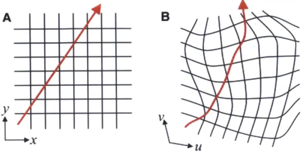
As we have seen, there are a great many ways of controlling the phonon band structure and tuning it to take certain values at certain frequencies. Much of the existing literature has focused on tuning band gaps and controlling which frequencies can propagate and which are damped, but there have also been efforts to define effective material parameters as a function of tuning signal, control the speed of sound, or control the angle of diffraction. To move towards more complex devices, however, it is useful to have a sense of how material parameters affect phonon dynamics - particularly in the case of effective material parame-ters. The intuition that is built up from conventional materials does not necessarily apply herc, as the material can possess such features as strong anisotropy (angular dependence) and inhomogeneity (spatial variation) and more exotic effects like complex-valued proper-ties, singulariproper-ties, negative phase velociproper-ties, or negative mass (or mass density matrices). A certain degree of useful intuition can be gained from a technique known as transformation materials. In addition to giving intuition, it is also a fruitful technique for determining what material parameters are necessary for generating an arbitrary effect.
2.2.1 Transformation Acoustics
To understand the operation of transformation materials, let's begin by considering the propagation of sound waves (the technique was originally developed for light waves
[100,
101, 102]). Expressing equation 1.5 in terms of pressure rather than strain gives1 a2
-aPt2P = V - P
)
(2.1)where A is the bulk modulus tensor (cijkk = 3A6ij, ij is the Kronecker delta), p is the
pressure (scalar), and p is the mass density tensor. If we transform to a new coordinate system using the Jacobian transformation matrix Jij (x -* x') = 8x'/&xj this becomes
1
a
2(j-iglT
1a2P
= V - det VP J (2.2)which is equivalent to the original equation if we make the substitutions (p--1)' = jj IjT / det J
and A' = A det J. Crucially, p' = p so this transformation leaves the pressure field unchanged even as the material is modified [103, 1041. This means that the material parameters ef-fectively define a geometric transformation. Note that this relationship between materials and geometry can be expressed in other terms, as in Leonhardt
[1011.
A particularly fruit-ful one 1 is to relate the equation for an inhomogeneous, anisotropic material in Euclidean spacetp=
a
((Pjl)iia p)(2.3)
to that of a homogeneous, isotropic medium (denoted by subscript 0) in curvilinear space
aeap
=
19
(p1-g
ajp)
(2.4)A0
we get the transformation A = A/.F/ and (p-1)ij = p-fjig'j. Thus an arbitrary anisotropic, inhomogeneous medium can be mapped to a purely geometric effect, as illustrated in Fig. 2-5. In this picture, to understand how waves propagate in some complicated medium it is not necessary to worry about any details beyond the geometry. This can reduce the problem of understanding wave transport considerably.
2.2.2 Cloaking Transform
Conversely, we can take a geometry that has interesting or unique effects on wave propaga-tion and translate that into a material prescrippropaga-tion. This gives an easy way of ascertaining the needed materials for complex or novel devices. By far the most common transformation considered [100, 101, 102, 103, 104, 1051 is the expansion of a point to a finite volume
r' =a+(b-a)*r/b (2.5)
where r is the radial component, a is the radius of the new volume (inner radius of the transformed geometry), and b is the outer radius of the transformed geometry (for r > b, the system returns to Euclidean coordinates). Thinking of this transformation in the reverse
(r = b * (r' - a)/(b - a)), anything within the finite region r < a gets mapped to the point
'An approach taken from Leonhardt and Philbin 11021 and adapted to acoustics in Sklan [1051. See also
A
y
I
A
B
Figure 2-5: Illustration of transformation materials concept. In both (a) and (b) a wave travels in a straight line, but in (b) the geometry is transformed to give a new geodesic. From J. B. Pendry, D. Schurig, and D. R. Smith, Science 312, 5781, 1780-1782 (2006). Reprinted with permission from AAAS [1001.
r = 0. This has the effect of rendering that entire region invisible, as illustrated in Fig. 2-6. Because the transformation matches the external geometry for r > b and is purely geometric for a < r
<
b, waves within the transformed region are radially compressed while waves outside the transformed region are left undeformed. In particular, there is no scattering off of any boundaries - the geometries are matched at r = b and smoothly transform inside the compressed region. This transformation therefore renders a finite region invisible while hiding the evidence of this effect from an external observer. It is therefore referred to as cloaking or a cloak of invisibility.We now consider the translation of this transformation into a material. For curvilinear coordinates such as are used in the radial transformation, J becomes
J
I
g-'-' (9'9uu 9UU &UOU9_' dv' gw, Ow' gvv
aV
gv'v' QU gWW Ow..
(2.6)where g is the metric tensor for each coordinate system (primed and unprimed), expressed in terms of a Euclidian reference frame. In the special case of the coordinate systems merely
Figure 2-6: Illustration of the cloaking transformation. (a) Cross-section view of the trans-formed geodesics. (b) Three-dimensional simulation of the geodesics. From J. B. Pendry, D. Schurig, and D. R. Smith, Science 312, 5781, 1780-1782 (2006). Reprinted with permission
from AAAS [100].
being a rescaling, as we consider here,
J = diag gu'u' Ou gv'v' OV
guu OU ,vv
O
'gw'w'
aw'
gww
Ow
(2.7)which allows us to express the metric tensor in terms of these coordinate transforma-tions
g = J .2 (2.8)
For a cylindrical transformation, grr = 1 = gzz, goo = r while grr = 1 = gz'z', go'o' = r,
Oz/Oz' = 1 = 00/00' and Or/Or'
J
Plugging everything in gives
b/(b - a) or = diag b b r' - a b-a'r' b-a P PGr' -a r'-a Po = Po r, b- a 2 Pz = po (b ) r' r, -a \
Ao
b -_a 2 / r k b)
r' -a 1 (2.9) (2.10a) (2. 1Ob) (2.1Oc) (2. 1Od)where, again, r' refers to the radial component between a and b in the cloaked frame. Note that in the special case of a two-dimensional transformation, pz is neglected as there is no spatial variation of the waves along this axis. On the other hand, for a spherical transformation b-a (r'\ P0 = a ,/ (2.11a) b (r - a no Po(2.-b P0 P0 ba (2.11b) b \ \ b a ) 3 r )2 . (2.11d) (b r -a)
In practice, these equations are sufficiently similar that most theoretical work is done for the two-dimensional cloak, while most experimental work is done for the spherical cloak (although there are other approaches, such as the carpet cloak first proposed by Li and Pendry [107, 108, 109] or the use of complementary media and external cloaks developed by Lai et al. [110, 111, 112]).
2.2.3 Realistic Cloaks
There are several important features to these transformation equations. They require an anisotropic mass density matrix, something that often requires artificially structured (meta-materials) materials to achieve. They also necessitate continuous functions to go from their background values at r = b to singular values at r = a. The requirement of a singularity at the boundary, however, is particularly difficult to achieve. In optics, this sort of singu-larity impossible for more than individual frequencies, as it implies a velocity in excess of the speed of light (since light must travel a longer distance around the cloaked region and still be faster than passing through the cloaked region). While acoustics is not so stringent, in practice this singularity is often relaxed. This can induce errors in the transformation equation, such as the lack of phase matching in Leonhardt and Tyc's non-Euclidean cloak [113]. It has been shown in multiple ways [114, 115] that a perfect cloak is truly perfect, and will block any component aside from a constant corresponding to the mean value of its
surrounding field (e.g. electric potential, pressure)2 [116, 117, 105]. To help characterize the effect of errors in a perfect cloak, Ruan et al.
[118]
considered the effect of removing a thin layer of thickness 6 from the inner lining of the cloak and then using scattering theory to determine how the magnitude of the scattering depends upon 6. They found that the scattering field converges to 0, but does so extremely slowly - less than o(6). Isi6 et al. [119] perform a similar analysis and show that it decays like 1/ ln 6. We will illustrate their methods more explicitly in Ch. 2.3.5, where there will be a concrete example to consider. Zhang et al.[120]
studies the creation of surface modes on the inner boundary of the cloak and the development of zero power transmitting penetrating modes.2.2.4 Thermal Cloaks
Concurrent with these efforts to understand the behavior of electromagnetic and acoustic cloaks, other people were seeking to extend these techniques. Devices like a concentrator (which does the opposite of a cloak and pulls waves towards the center
[121,
122]), rotators [123, 124, 1251, illusion techniques (making an object appear like another, or like multi-ple copies of itself [126, 127, 128, 129, 130, 131, 132]), and space-time cloaks (extending the formalism to allow for temporal transformations from moving media, thereby cloaking events rather than objects [133]) were developed using other coordinate transformations. Additionally, the transformation materials was applied to other classes of wave phenomena [134, 135, 136, 137, 138, 139, 140, 141, 142] and to diffusion effects [143, 144, 145]. In par-ticular, it was shown that both the ballistic transport of phonons illustrated in the acoustics examples above, but also the diffusive transport of phonons by the heat equation met the transformation materials requirements [146, 147, 148, 149, 150, 151, 152, 153]. Guenneau et al. [147] first proposed the transformation, Schittny et al. [148] and Ma et al. [150] de-veloped designs for the cloak. Narayana et al. [149] dede-veloped a design for quasistatic heat flux rather than temperature Narayana and Sato[151]
experimentally tested this design. Li et al.[153]
developed a simultaneous cloak for light and temperature. Guenneau and Amra [154] designed a thermal rotator (also tested in Naranaya and Sato TC6). He and Wu [155]2
This can be seen by noting that the steady state mean value takes the form V2f = 0, or Laplace's equa-tion. This eigenvalue equation obeys the property f(ro) = ffs() fdA/ ffs(ro) dA for any sphere centered at ro (i.e. S(ro). In other words, the value at the center of a sphere is necessarily equal to the mean value over the sphere's surface.
designed a thermal illusion device.
To demonstrate the transformation materials prescription for diffusive phonon transport, we begin with the heat equation
pcpatT = a, (rx0a.T) (2.12)
where p is the density, cp the specific heat capacity, T temperature, and K the thermal conductivity. Following the standard method, we change coordinates
,fgp'c'at T -= az
(nfrgb8jaT)
. (2.13) So-= no V'giJ (2.14a)
P'p = Pocpov/gg (2.14b)
Taking the two-dimensional circular cloak for concreteness gives
Kr = r/ a (2.15a)
-O
= no / (2.15b)
r -a
pc, = pocpo (,b a)2 r a (2.15c)
Note that these have different forms than the material parameters of equation 2.10a-c, but there are clear similarities due to their shared geometric origin. In particular, these similarities allow theoretical work on cylindrical cloaks to be applied to experimentally realized spherical cloaks with only minor modification.
2.3
Testing the Accuracy of Diffusive Cloaks
While the transformations involved in the construction of a thermal cloak bear some resem-blance to those used in other cloaking devices, it is important to remember that they are not the same. Not only are the materials different, but the equations are fundamentally different. Prior to the treatment of the heat equation, all transformation media techniques had been applied solely to the wave equation (a hyperbolic partial differential equation) or Laplace's equation (an elliptic partial differential equation). The heat equation is a diffusion equation, and therefore a parabolic partial differential equation. What this means is that signals propagate differently for the thermal cloak than for the previously analyzed cloaks. The standard picture of far-field scattering does not necessarily apply. This difference is exacerbated by the material differences between the acoustic or optical wave equations and the heat equation. The range of available materials and the need to achieve something approaching a singularity at the inner boundary necessarily limits the performance of any cloak.
To make a realizable cloak, previous researchers
[148,
150, 151] have focused particularly on the engineering of the thermal conductivity l. While it was clearly understood that the necessity of using real materials kept them from reaching the perfect inner boundary, improved fabrication techniques allowed them to push the limits of what had been achieved3. The need to engineer the volumetric heat capacity pcp, on the other hand, was assumed to
be negligible. In part, this was due to the choice of experimental tests applied to the thermal cloak, namely the application of fixed temperatures at opposite sides of a domain surrounding the cloak (see Fig. 2-7). Since pcp only appears in conjunction with time derivatives of the temperature, the onset of a stationary steady state solution eliminates the heat capacity. It has no effect on the steady state temperature distribution, just the transient component. On the other hand, the utility of a cloak that only works in an unchanging environment is fairly limited. At most, it can regulate temperature distributions; say by acting as a thermal insulator.
3
In particular the ability to fabricate micron and nanoscale resonators led to the development of metama-terials (mametama-terials whose properties are determined by their structure not their chemical composition). Meta-materials were essential in providing the material properties required for the earliest cloaks [100]. Similarly, greater resolution in nanofabrication allows for greater flexibility in engineering the thermal conductivity.
Figure 2-7: Model for finding the location of a thermal cloak of radius b with cloaked domain of radius a. Two heat baths (red and blue rectangles) are placed at opposite sides of the cloak, which is confined to a thermally isolated domain. Heat flows between the baths (red lines), passing through a perfect cloak without distortion. For an imperfect cloak, however, heat is also scattered from the boundaries of the cloak. Although the scattered heat diffuses, a thermometer near the cloakAA2s surface can detect it. From Sklan et al. 11561.
In recognition of this fact, many researchers have focused on the transient effects 147, 148, 1501. There too, the testing of the cloak's performance has been largely qualitative. Moreover, they have assumed that the replacement of an inhomogeneous heat capacity with a constant one is negligible even in this regime. Schittny et al. 11481, for example, em-ploy an approximate cloak design developed in Guenneau et al.
11471
(where constant pcp was explicitly assumed) while still claiming to achieve transient thermal cloaking. Indeed, they even observed in their experiments that the specific heat was not constant in their device, but they sought to correct for this deviation from their homogeneous pcp model. Additionally, Ma et al. 11501, simplify their transient cloak design by assuming that pcp commutes with spatial derivatives to good approximation, which immediately implies that pcp is approximately homogeneous. Due to this confusion, other researchers have sought to extend thermal cloaking to other diffusive transport problems, particularly chemical diffu-sion. Chemical diffusion obeys the equation ten = V - (DnVn) for chemical concentrationn
and diffusion constant Dn. Researchers[143,
1441 have again assumed that, because pcp was negligible for w - 0 steady state thermal cloaks, the steady state thermal cloak designstranslate directly into time-dependent chemical diffusion cloaks (despite the fact that such an analogy maps pcp to unity everywhere).
In this section, we therefore analyze the performance of this class of thermal cloaking (i.e. cloaks which rely upon engineering K but neglect pcp), which we term the steady state cloak.
2.3.1 Scattering Solutions to the Cloaked Heat Equation
Understanding the perfect cloak's connection to the background medium is foundational to understanding the steady state cloak Starting from equation 2.12, we can take the Fourier transform in time and use a separable solution (in polar coordinates) T(r,
0,
t) =R(r)e(O)T(t) to get
iWPoCpoR = d d 12
WPC R = (r dR) - -2R (2.16)
KO r dr dr r2
where 1 is the eigenvalue to the 9 dependent portion of the separated equation, W is the eigenvalue of the time dependent portion of the separated equation, pocpo is the volumetric specific heat of the background medium, io is the thermal conductivity of the background medium, and i is v/-1. This can be re-written as the differential equation defining the modified Bessel functions (either Ii(z) or Ki(z) 11581) by making a change of variables
z = 0r for
0.
Hence, the time-dependent (i.e. the transient regime) solution has eigenfunctions of the formT 1 (r, (r 0, w) = (a 11(z) + b1K1(z)) e'1O2w. (2.17)
with al and bj being arbitrary constants determined by the initial and boundary condi-tions.
On the other hand, when w = 0 (i.e. the steady state) the temperature distribution becomes defined by the solution to Laplace's equation
for 1 7 0 (Al and B1 are generalizations of al and bl) and
T(ss) = A0 + Bo ln(r) (2.19)
for 1 = 0. Thus, the general solution can be written T(r, 6, w) = EG T(ss) + hz=0 1 1~r(tr)
When considering the perfect cloak (PC) defined by equation 2.15a, we can use the old coordinate transformation of
b
r' = (r - a) (2.20)
b - a
(again, b is the exterior radius of the cloak, a is the radius of the cloaked domain, r' is the coordinate system - in real space - inside the cloak, r is the coordinate system of the mathematically equivalent geometry defined in Ch. 2.2) to reduce the solution in the primed coordinates to the homogeneous case defined be equation 2.12. Specifically, we use solutions that depend upon the new effective position z = v//(b - a) * kor, where ko = rwpocpo/ho
is the effective thermal wave vector of the homogeneous background.
For a steady state cloak (SSC) the material parameters are
o = / -a (2.21a)
r'
R = no I r/(2.21b)
r -a
pp = PoCPo (b T (2.21c)
where rl measures the impedance mismatch between the cloak's outer boundary and the background (7 = 1 is impedance matched). We can no longer use the coordinate transfor-mation trick but instead must brute-force the solution (following Sklan et al. [156]). Using a new effective position variable x =
fiwpocporb/so(b
- a)(r - a) and again assuming aseparable solution gives
12
0= ax(xcR)- [+x +Ka R (2.22)
where K = fiwpocporb/o(b - a). We solve this equation by means of the method of
Frobenius Rl(x) =
Eb
x'7I1 with recurrence relation [156]1