Distributed Speech Recognition
within a Segment-Based Framework
by
Laura S. Miyakawa
B.S., Carnegie Mellon University, 2001
Submitted to
the Department of Electrical Engineering and Computer Science in Partial Fulfillment of the Requirements for the Degree of
Master of Science
at theMassachusetts Institute of Technology
June 2003@Massachusetts
Institute of Technology, 2003.All rights reserved.
Signature of Author ...
Department of Electrical Engineering and Computer Science May 21, 2003
C ertified by ... .. . ... I. Lee Hetherington
Research Scientist Department of EeftrigalEngi46erintpnd Conjputer Science
Accepted by ...
Arthur C. Smith Chair, Department Committee on Graduate- Students
MASSACHUSETTS INSTITUTE OF TECHNOLOGY
Distributed Speech Recognition
within a Segment-Based Framework
by
Laura S. Miyakawa
Submitted to the Department of Electrical Engineering and Computer Science in June, 2003 in partial fulfillment of the requirements for the Degree of
Master of Science
Abstract
The widespread acceptance of personal digital assistants (PDAs) has led to research into the interaction people have with these devices. Speech is a natural choice for this interaction. However, traditional speech recognition systems require an abundance of memory and processor cycles. On limited machines like an iPAQ, implementing an entire speech recognition system would be debilitating to the device. A solution to this problem is to allow the iPAQ to communicate with a server that does the actual recognition task. This method is better known as distributed speech recognition (DSR).
This thesis examines the problems of implementing DSR on an iPAQ. We faced the challenge of reducing the bandwidth required by the system while maintaining reasonable recognition error rates. We examined using a fixed-point processing in reducing the computational demand put on the iPAQ. The word error rates for the baseline floating-point front-end system and our fixed-point front-end were 9.8% and
9.6% respectively. However, using the fixed-point front-end actually increased our bit
rate. Next, we focused on the effects of quantizing Mel-Frequency Cepstral Coeffi-cients (MFCCs) before sending them to a recognizer on the server side. We evaluated both scalar and vector quantizers using non-uniform bit allocation. Our optimal vec-tor quantizer reached a word error rate of 9.8% at 6400 bps. Finally, because our recognizer further processes the MFCCs to arrive at boundary measurements, we ex-plored the idea of quantizing these boundary measurements. The scalar boundary measurement quantizer reached a word error rate of 9.6% at 150 bits per hypoth-esized boundary. We averaged 21.1 hypothesize boundaries per second on our test data; thus, we could transmit boundary measurements at 3165 bps and maintain a
9.6% word error rate.
Thesis Supervisor: I. Lee Hetherington Title: Research Scientist
Acknowledgments
I would like to acknowledge my thesis advisor Lee Hetherington for his patience, flexibility and willingness to help me debug code. I also need to thank Scott Cyphers for his help with the iPAQ and the audio server. A debt of thanks is owed to the Spoken Language Systems group in its entirety for all the critical thinking they put into this thesis. Naturally, included in that is my office. Han, Ernie and Alicia have a special place for all of help they have given me. From basic concept understanding, to writing scripts, to just putting up with all my chatter, these three have seen it all.
Outside of research, I need to thank the 6.1 girls for all their support and advice in navigating MIT. As well, my family for lending me support from afar and always keeping things interesting at home. And finally, I have to thank Jeff for doing the dishes and the laundry when I've been slaving away at the office, for helping me design some of the figures in this thesis, and for basically being wonderful.
This research was supported by a Lucent fellowship and by DARPA under Con-tract N66001-99-1-8904 monitored through the Naval Command, Control, and Ocean Surveillance Center.
Contents
1 Introduction 13
1.1 Problem Definition . . . . 13
1.2 Previous Work . . . . 14
1.2.1 Fixed-Point Front-End . . . . 14
1.2.2 Distributed Speech Recognition . . . . 14
1.3 Goals and Overview . . . . 16
2 Background 19 2.1 Mel-Frequency Cepstral Coefficients . . . . 19
2.2 Boundary Measurements . . . . 21 2.3 Fixed-Point Numbers . . . . 23 2.4 Q uantization . . . . 24 2.4.1 Scalar Quantization . . . . 25 2.4.2 Vector Quantization . . . . 26 2.5 Chapter Summary . . . . 28 3 Fixed-Point Front-End 29 3.1 Algorithm Optimization . . . . 29
3.1.1 Framing, Pre-emphasis, Window . . . . 29
3.1.2 FFT and the Mel Filter Bank . . . . 30
3.1.3 Natural Log and DCT . . . . 31
3.2 Testing Conditions . . . . 32
3.3 R esults . . . . 33
3.3.1 Word Error Rate . . . . 33
3.4 D iscussion . . . . 34
4 Quantization of Mel Frequency Cepstral Coefficients 35 4.1 Quantizer Design . . . . 35
4.1.1 Bit Allocation for Scalar and Vector Quantization . . . . 35
4.2 R esults . . . . 38
4.2.1 Word Error Rates . . . . 38
4.2.2 Computational and Storage Costs . . . . 39
4.3 Discussion . . . . 40
5 Quantization of Boundary Measurements 43 5.1 Quantizer Configuration . . . . 44
5.1.1 Uniform Bit Allocation . . . . 44
5.1.2 Eigenvalue Weighted Bit Allocation . . . . 44
5.2 Results and Costs . . . . 45
5.2.1 Word Error Rates . . . . 45
5.2.2 Computational and Storage Costs . . . . 46
5.3 Discussion . . . . 48
6 Conclusions 51 6.1 Summary . . . . 51
6.2 Future Directions . . . . .. . . . . 52
List of Figures
1.1 Real-time factors for each version of front-end code from
[3].
. . . . . 151.2 Diagram of of IS-641 Encoder and Decoder with locations where fea-tures are extracted labeled with Cx from [11]. . . . . 16
2.1 Illustration of the front-end. . . . . 19
2.2 Illustration of the Mel-Scale Filter Bank. . . . . 20
2.3 Illustration of the computation of boundary measurements. . . . . 21
2.4 Illustration of full boundary measurements computation. . . . . 22
2.5 Illustration of Uniform Quantization Scheme in 2.5(a). Illustration of Non-Uniform Quantization Scheme in 2.5(b). . . . . 25
2.6 Illustration of a Uniform Scalar Quantization Scheme for a 2-D vector shown in 2.6(a). Illustration of a Uniform Vector Quantization Scheme for a 2-D vector shown in 2.6(b). . . . . 26
2.7 Illustration of binary splitting training. . . . . 27
3.1 Plot of error versus angle for magnitude approximation when actual magnitude is held constant at 1. . . . . 32
4.1 Plot of Scalar Quantization versus Vector Quantization. . . . . 38
4.2 The computation costs for the scalar quantizer and all four vector quantizers are shown in Figure 4.2(a). In Figure 4.2(b) the storage costs for the scalar and vector quantizers are shown. . . . . 41
5.1 Plot of word error rates for various boundary measurement quantiza-tion schem es. . . . . 45
5.2 The computation costs for the scalar quantizer and all four vector quantizers are shown in Figure 5.2(a). In Figure 5.2(b) the storage costs for the scalar and vector quantizers are shown. . . . . 47
5.3 Overall performance of quantized recognizers. . . . . 49
List of Tables
1.1 Some results from Digalakis, et al, 1999 [4] . . . . 15
4.1 Progression of correlation matrices for the first method of obtaining correlation based subvectors. . . . . 37
4.2 Subvector Partitions for VQ experiments. . . . . 37
4.3 Bit rates, Allocation and corresponding Word Error Rates for Scalar Q uantization. . . . . 39
4.4 Bit rates, and Word Error Rates for Vector Quantization Schemes. . . 40
5.1 Scalar quantization results using eigenvalues as guides for bit allocation. 46
5.2 All of the results shown in this table are for a vector quantizer with 5 coefficient per subvector. The first two rows of this table show bit
allocation and word error rates for uniform distribution of 50 and 60 bits per boundary. The third row shows bit allocation and word error rates for the 60 bits per boundary (non-uniform bit allocation vector quantizer). The next to the last row shows the uniform bit allocation for a total of 100 bits per boundary, and the last row shows the word error rate and bit allocation for a gently weighted non-uniform bit allocation . . . . 47
5.3 Bit rates and word error rates for quantizing boundary measurements versus M FCCs. . . . . 48
Chapter 1
Introduction
1.1
Problem Definition
The widespread acceptance of personal digital assistants (PDAs) has led to research into the interaction people have with these devices. Because they are too small to have traditional keyboards, developers are constantly looking at better ways to manipulate these hand-helds. Speech is a natural choice for this interaction. Speech requires no special learning on the part of the user and enables the screen of the PDA to be used for other things. However, traditional speech recognition systems require an abundance of memory and processor cycles. On limited machines like an iPAQ, putting an entire speech recognition system on it would be debilitating to the device.
A solution to this problem is to allow the iPAQ to communicate with a server that
does the actual recognition task. This method is better known as distributed speech recognition.
There are two main problems faced when implementing a distributed speech rec-ognizer. The first is how to choose which parts of the recognition process are handled
by the server and which by the client (the iPAQ in our case). Many systems have
been built that employ server-only processing. When this is the scheme used, the speech is merely compressed on the client side then transmitted to the server for expansion, feature extraction, and recognition. Another common place to break up the computation flow is at the feature level. Here, the features are computed by the client, then quantized and sent to the server for recognition. This scheme has the added advantage that feature vectors tend to be more robust to quantization than the original signal and, therefore, require less bandwidth than original waveform. The second problem faced by distributed speech recognition stems from the necessity to quantize. In many packet-based transmission schemes or narrow-band channels the bit rates of these features are unattainable. Thus, we are forced to quantize these
features to a feasible bit rate. If the quantization scheme is chosen carefully, it can actually improve the accuracy of the recognizer by removing unnecessary information.
1.2
Previous Work
For this thesis we looked at work done both in the implementation of fixed-point processing and in distributed speech recognition.
1.2.1
Fixed-Point Front-End
In an attempt to lower power consumption on the Hewlett Packard Labs Smartbadge IV that is the client of a distributed speech recognition system, Hewlett Packard im-plemented a fixed-point front-end [3]. The Smartbadge IV uses a fixed-point stron-gARM processor which has a floating-point emulation program to run floating-point code similar to the processor used in the iPAQ. Hewlett Packard used the HMM-based
SPHINX II recognizer as their baseline system. They did not concern themselves with
the compression and transmission of their features, merely the computation of them. The real-time factor for each code version of their front-end can be seen in Figure 1.1. The real-time factor is the amount of time to process 1 second of speech. Here, for example, the baseline system takes 1.51 seconds to process 1 second of speech. The optimized floating-point code included special FFT algorithms which reduced the size of the FFT by half. They also implemented an optimized floating-point front-end that used 32-bit floating-point calculations. The fixed-point system reduces the computa-tion time of the baseline by 98%. The word error rate (WER) for all of the systems except the fixed-point version is 4.2%. For the fixed-point system the word error rate is 4.3%. This increase of 0.1% was eliminated by training on fixed-point front-end data.
1.2.2
Distributed Speech Recognition
In the interest of performing speech recognition over the Internet or over cellular telephones much work has been done in the quantization of features. Some of this work focuses on the quantization of Mel-Frequency Cepstral Coefficients (MFCCs) [4]. Others focus on the quantization of coded speech for both recognition and synthesis
[9, 11].
One study that focused on speech recognition over the Internet looked at speech compression algorithms and scalar and vector quantization of MFCCs [4]. Their first experiments were doing server-only processing. They used both [t-Law and GSM compression algorithms, but neither proved to be a reasonable method since both
1.8 1.6- 1.4-01.2 -LL 1 IT0.8 G"0.6 - 0.2-0"
baseline opt. float 32-bit float fixed
Figure 1.1: Real-time factors for each version of front-end code from [3].
Bit Rate (Kbps) WER
Baseline - 6.55%
constant bits per 10.4 6.53%
coefficient, non-uniform 3.9 6.88%
variable bits per 3.0 6.55%
coefficient, non-uniform 2.4 6.99%
Vector Quantization 2.0 6.63%
Table 1.1: Some results from Digalakis, et al, 1999 [4].
doubled the baseline word-error rate. They also explored using both uniform and non-uniform scalar quantization of the MFCCs with a constant number of bits per coefficient. Some of their results are reported in Table 1.1. Here, they found they could reduce the bit rate to 3.9 Kbps and only increase the WER by 5% relative when using non-uniform scalar quantization as seen in Row 3 of Table 1.1. In addition they explored scalar quantization where the number of bits per coefficient could vary. Do-ing this allowed them to decrease the bit rate to 2.8 Kbps and slightly improve the word error rate over the constant bit allocation method. Finally, they tried product-code vector quantization (VQ). To determine subvectors they used both correlation-based partitioning and knowledge-correlation-based partitioning. Knowledge-correlation-based partitioning outperformed the correlation-based partitioning. This may have been caused by the small data set used to determine the correlation-based partitioning or the low corre-lation between coefficients leading to arbitrary partitioning. The results of one test using knowledge-based partitioning is shown in Table 1.1.
IS-641 Encoder IS-641 Decoder
Speech Analysis Quantize Unquantize Synthesis
Co C1 C2 C3 C4
Figure 1.2: Diagram of of IS-641 Encoder and Decoder with locations where features are extracted labeled with Cx from [11].
In another study perceptual linear predictive analysis (PLP) was quantized and transmitted for distributed recognition [9]. PLP is similar to LPC (linear predictive coding) in that it creates and all-pole model for each frame of the speech. It differs because it exploits some auditory perception information to reduce the number of pa-rameters needed per frame. They quantized and unquantized these papa-rameters using vector quantization and used dynamic time warping to recognize the digit sequence. They showed the remarkable ability to reduce the bit rate to 400 bps with statistically similar word error rates to using no quantization. At this rate both PLP and speech coder parameters could be transmitted over a standard cellular channel.
A fairly comprehensive study used the IS-641 coder and explored using features
from different parts of the coding stream for recognition [11]. The IS-641 coder can be thought of in two blocks, an analysis block which is similar to LPC analysis and a quantization block. They look at the word error rates generated when features are computed from the original speech waveform, from just after the analysis block, from just after the unquantization, and from the decoded speech as shown in Figure 1.2 by the labels CO through C4. They also did experiments training on one set of features and testing on another. In addition they ran tests on large vocabularies, recognition in the presence of noise, and recognition with channel impairments. They found that when they included voicing information with features generated at C3, they got statistically similar results to those using features derived from the original speech,
Co.
1.3
Goals and Overview
This project was motivated by the desire to reduce the bandwidth needed in a dis-tributed speech recognition system on an iPAQ. Earlier work by Scott Cyphers of
SLS yielded a recognition system that included an iPAQ client that transmitted an
p-law utterance to a server for recognition. To reduce the bandwidth required, we needed to do more than just compress the speech waveform. Previous work by Jon Yi of SLS showed that by quantizing the MFCCs with a uniform scalar quantizer,
the bandwidth needed to transmit MFCCs could be decreased while the recognition accuracy remained unchanged.
This thesis can, then, be viewed as three distinct parts. The first is the creation of a fixed-point front-end for execution on the iPAQ. The second is the study of the the effects of quantization of the cepstral coefficients on the word error rate of the recognizer. The third is the investigation of the effects of quantization of the boundary measurements on the word error rate of the SUMMIT recognizer.
Because the iPAQ uses a fixed-point StrongARM processor, we implemented a fixed-point front-end to compute the cepstral coefficients. The goal of this portion of the project was to translate our floating-point front-end into fixed-point computation avoiding the pitfalls of overflow while reducing the computations needed on the iPAQ. Once the cepstral coefficients were computed, we performed non-uniform scalar and vector quantization and looked at the effects on word error rate. We used a greedy algorithm to do bit allocation where a variable number of bits are used for each of the cepstral coefficients. In addition we computed the covariance matrix for the MFCCs and used several algorithms to come up with good covariance-based partitions for product-code VQ. We also tried knowledge-based partition methods for product-code
VQ similar to [4].
Many people have studied putting the computation of MFCCs on the client. This is natural for a recognizer that is HMM-based since its features are MFCCs. In our
SUMMIT recognizer, however, we perform additional computations to compute bound-ary measurements for our features. Because of this difference we explored the effects of quantizing these boundary measurements with both scalar and vector quantiza-tion methods. Scalar and vector quantizaquantiza-tion tests similar to the ones done on the MFCCs were run on the boundary measurements with a few differences. Because the boundary measurements are derived to be uncorrelated with each other, covariance-based partitions were not explored. We did explore weighting the bit allocation by the eigenvalues.
Chapter 2 goes into the background for front-end processing, scalar and vector quantization and fixed-point processing. Chapter 3 discusses the research issues en-countered when implementing the fixed-point front-end. In Chapter 4, we give results for the experiments in quantizing the MFCCs. Chapter 5 reports the results from recognition experiments using quantized boundary measurements. Finally Chapter 6 summarizes and draws conclusions.
Chapter 2
Background
In this thesis we deal with the ideas of creating a fixed-point front-end and quantizing feature vectors. In the following sections we give background information on how the MFCCs are computed in the front-end, boundary measurements computation, fixed-point numbers, and quantization.
2.1
Mel-Frequency Cepstral Coefficients
Mel-Frequency Cepstral Coefficients (MFCCs) are a commonly used representation of the speech waveform. They are the features used most regularly in HMM-based speech recognizers and are intermediary features within the MIT SUMMIT segment-based recognizer. Some good references for the computation of MFCCs are [5, 17]. A block diagram of the front-end which computes the MFCCs is included in Figure 2.1.
A brief description of each block is given.
Speech starts as a continuous waveform. It is recorded and discretized. In order to process it, we break it into small overlapping blocks or frames and analyze each frame's frequency content. This first dividing of the stream of speech into individual frames occurs in the Framing block. In our system we compute a frame every 5 ms, and each frame is 25.6 ms long. We will use xi [n] to represent the ith frame of the input speech.
Next, we run each block through a pre-emphasis filter p[n] (as defined in
Equa-Pre-e+ phasize FFT1 Mel Filter Log DCT MFCCs
x[n] x [n] y [n] Y [k] Z[j] Zj] c,[n]
Frequency 0
Figure 2.2: Illustration of the Mel-Scale Filter Bank.
tion 2.1) which puts more emphasis on the high-frequency regions of the waveform. We apply this gentle high-pass filter to counteract the radiation characteristics of
the mouth. We, then, multiply the block by a window w[n]. Here, we use a
Ham-ming window which tapers toward its edges to minimize the interference effects from framing. Let yi[n] represent the output of the Pre-emphasize and Window block.
p[n] 6[n] - .976[n - 1] (2.1)
yi[n] =
w[n](p[n]
*xi[n])
Next we take an FFT. The FFT computes the frequency spectrum of the frame.
Y [k] is the output of the FFT and is given by:
Y[k] = FFT{yj[n]}
Now that we have the frequency spectral information we can filter it into various bands. Illustrated in Figure 2.2 is an approximation of the Mel-Scale Filter Bank we used[2]. A Mel-Scale Filter Bank has filters which are linearly spaced in the low frequency range and logarithmically spaced in the high frequency range. This means that in the high frequency range we are melding more of the frequencies together than in the low frequency range. This filter bank approximates how the human ear filters the frequencies it encounters. We apply this filter bank to the square of the
magnitude of Y [k] The output of the filters is Zi [J], and the Mel-Filter bank is H [k].
N/2
Zj[ j] = I |Y[k]|12Hj[k] (2.2)
k=O
The next block is the Log. This block takes the natural log of the output of the Mel Filters.
Zi[j] =_ ln(Zilj])
The DCT block is a Discrete Cosine Transform. In this scenario it yields the same
CMIS
MFCC Full Boundary PCA Trim eBoundary
Stream Computation Measurements
Boundary> Detector
Figure 2.3: Illustration of the computation of boundary measurements.
domain), but uses less computation. Because we have an FFT, Log and DCT in sequence, we are transforming our data into the cepstral domain, creating MFCCs. We save only the first 14 MFCCs, ci[n].
ci[n] = DCT{Zi[j]}
We compute the cepstrum to deconvolve the source from the filter [13, 14, 19]. In our case the vocal source is either vibration from the vocal folds or noise, and the filter is derived from the shape of the vocal tract. It is the shape of the vocal tract that gives speech the spectral characteristics we distinguish to understand different sounds. Getting rid of the vocal source is desired in speaker-independent speech recognition systems since, in English, pitch information does not give us information about the words that were spoken. In fact we hope to throw away pitch information so the same models can be used for speakers with different speaking pitches.
2.2
Boundary Measurements
A typical speech recognizer uses an HMM with MFCCs as its features. The SUMMIT
system, however, goes a few steps further in processing to get features which represent boundary measurements [8]. A block diagram of how we get from MFCCs to boundary measurements is in Figure 2.3.
The MFCC stream computed in the previous section is used in two different blocks. One is Cepstral Mean Subtraction (CMS) [10, 17, 7]. Mathematically, this is just computing the mean for each coefficient across all the frames in the utterance and subtracting that mean from each cepstral vector as seen in Equation 2.3. Since we are dealing with the cepstrum, responses that were convolved in the time domain are now added. By subtracting off the mean, we are essentially subtracting off any constant convolutional effects. One example of a constant convolutional effect is the frequency response of the room. By subtracting off the mean, speech that is recorded in an opera house and speech recorded in a closet should yield the same features.
full boudr
M F C Co
uec t o r
time proposed boundary frame
Figure 2.4: Illustration of full boundary measurements computation.
1T
=
[n] = ci[n] - TE
cj
[n] (2.3)j=1
The simultaneous block Boundary Detector hypothesizes where boundaries be-tween segments may be. A segment can be thought of as one phone, so in the word bad boundaries should be detected between the b and the a and between the a and the d.
Once frame j is hypothesized as a boundary frame, the frames around it are buffered and averaged together in the Full Boundary Computation block. A schematic of what goes on in this block is included in Figure 2.4. In this figure the vertical hashes represent a vector of normalized MFCCs. The shaded boxes in Figure 2.4 show which vectors get averaged together. For example, if the proposed boundary frame is Ej[n],
then Ej+i[n] and B3+2[n] will be averaged together as will j-4[n], 6j-5 [n], Ej-6[n] and
Ej-7[n]. This yields 8 averaged cepstral vectors, each of length 14, which are then stacked to create one very big full boundary vector of length 112.
The next block, PCA, does a principle component analysis that multiplies the boundary vector by a rotation matrix which approximately makes the coefficients uncorrelated. The output vector is still of length 112, but now the coefficients are ordered by variance with the coefficients with highest variance first. We then trim this
vector down (in the Trim block) to its first 50 coefficients to reduce the computational demand. This paring down of the boundary vector also aids in classification because higher dimensional features require more training data. Because of the ordering imposed by the PCA, we know that we are keeping the 50 coefficients that have the highest variance and hopefully the 50 most important coefficients.
2.3
Fixed-Point Numbers
A fixed-point number is an integer that the programmer can interpret as rational
number. When you use a floating-point number to represent fractional information, you have no control over how many bits and, therefore, how much accuracy, is assigned to that fraction. Your computer handles this and increases or decreases the number of bits used for the fractional portion of a number depending on the resolution needed. In a fixed-point number the developer gets to decide how much resolution is given to the fractional information. The best way to explain this is in an example. Let's assume that we have an unsigned 8-bit fixed-point number. To keep track of the number of bits used for the fractional information (or behind the decimal point), we adopt a Qn notation where n designates the number of fractional bits
[3].
Let say the binary representation of our number is 01101011. If this number is in QO then there are 0 bits behind the decimal point, and, thus, all bits are used for the integer portion of the number, so we would interpret it as the number 107.01101011. = 2 6 + 2' - 2 3 - 21 - 20 = 107
If this number is in Q1, then the last bit is used for the fractional portion. Similar to
how each bit represents a positive power of two in binary, any bits used behind the decimal points now pertain to the negative powers of two.
0110101.1 = 2 + 2 + 22 + 20 + 2-1 = 53.5 If this number was in Q6 format, it would represent:
01.101011 = 20 + 2-1 + 2- + 2 + 26 1.671875
There are a few things to note. First 53.5 is half of 107. 1.671875 is 1/64 of 107. In fact, to translate any integer into its Qn value, simply divide that integer by 2". Another point to consider is the trade-off between the largest integer that can be represented and the resolution of the fractional portion. Notice that in Q6 the largest integer that can be represented is 3 while in QO it is 255. This factor comes into play when one must consider the possibility of overflow in computation. We will explore this problem further in Chapter 3.
2.4
Quantization
Quantization
is the process of considering a variable that could take on any value (continuous-amplitude) and restricting it to take on only a discrete set of values [20]. In this way a value can be represented with less information (bits). Most quantization schemes follow the method below." Initialize: Choose a number of levels or bins. Determine which ranges of values
belong to each bin. Choose a representative (or quantized) value for each bin. Assign each bin a label.
" Quantize: For a given value of a variable, choose the bin it falls into and record
its bin label.
" Unquantize: Translate each bin label to the representative value of that bin. A key metric of how well a quantizer works is a distortion measure (also known
as a dissimilarity measure or a distance measure). The distortion measure gives information about the difference between the original value and the quantized value.
A simple quantization example is a street address on a letter; it has many levels of
quantization. Let's let our distortion measure be the likelihood that a letter delivered to the quantized address will get to me. The letter will start with just my name on it and a 37 cent stamp. First let's think about how the state in the address is an example of quantization. There are 50 states, so there are 50 quantization levels. the range of each bin is determined by the state boundaries. Let the quantized value for each state be the address of city hall in the state's capital. The label for each bin is the state's two letter abbreviation. On the state level my address is quantized to the label MA and is unquantized to the address of the state house. Since it is unlikely that any mail delivered to Beacon Hill would make it to my house in Somerville, we can say the quantization error is high. Next we quantize each state. Each state is quantized by city. Let the quantized value of the address now be city hall. My address is now quantized to the label Somerville, MA and unquantized to the address of city hall in Somerville. At this level of quantization, it is slightly more likely that I will get the piece of mail, but the odds are still against me. At this point, let's consider the zip code. A zip code contains information about not only state and city, but also about a zone within a city. If we let the quantized address be the address of my local post office, then my chances of getting the letter might be estimated at about 50/50. And the process continues. The post office uses these course to fine quantizers to ensure that a letter can be easily deliverable with a reasonable amount of information in the address.
0. 0. 0. 0. 8 6 42 --1 0 1 2 -f2 -1 0 1 2 (a) (b)
Figure 2.5: Illustration of Uniform Quantization Scheme Non-Uniform Quantization Scheme in 2.5(b).
in 2.5(a). Illustration of
2.4.1
Scalar
Quantization
Scalar quantization is just the quantization of each variable by itself. There are two main schemes of scalar quantization: uniform and non-uniform. In uniform quanti-zation, sometimes called linear quantiquanti-zation, the bins are equally spaced across all possible values. Non-uniform quantization merely implies that the bins are not of equal size. A common non-uniform schemes uses information about the probability distribution of a variable to make each bin have the same probability of occurring. Examples of each are shown in Figure 2.5. In these figures the vertical lines represent the boundaries of the bins, and the curve is a Gaussian distribution for the vari-able being quantized. In the uniform quantization example, each bin has the same width. In the non-uniform quantization scheme, the bins are narrower where there is a higher probability of a value occurring. The advantage of the non-uniform scalar quantization is that by having bins of variable size, the expected value of the distor-tion measure can be minimized [12]. In reality we tend not to know the underlying statistics of our variables. To handle this problem we train our quantizers on the type of data it will see to approximate the distribution of the variable.
The most common distortion measure is the mean-square error (mse) [12]. Here we represent the ith value of our original variable x as xi, its quantized value as xi,
0.8- 0.6- 0.4-
x2 x, x2 0 , \ xi (b) (a)
Figure 2.6: Illustration of a Uniform Scalar Quantization Scheme for a 2-D vector shown in 2.6(a). Illustration of a Uniform Vector Quantization Scheme for a 2-D vector shown in 2.6(b).
and the mean-square error as d(x,
z).
N
d(x, ;) (Xi - i)2
2.4.2
Vector Quantization
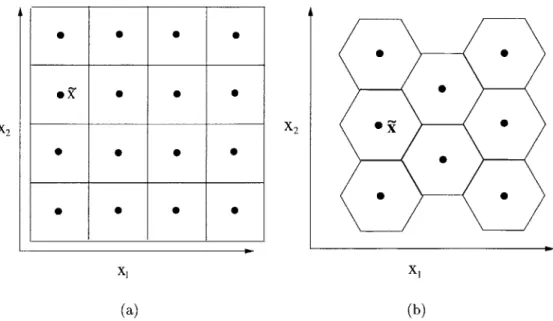
Instead of quantizing just one continuous variable, let's consider the quantization of a vector of continuous variables
[18].
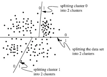
Let x = [x 1x2 ... XINT. For visualizationpurposes we will deal with the 2 dimensional case. Figure 2.6 shows two uniform vector quantization schemes. Both of these quantizers partition the space into a uniformly shaped bin and then choose a quantization value for that bin. As we get into higher dimensional spaces it is harder to choose a shape for a bin. Especially when we know little about the statistics of this data. In this case we train our quantizer on a randomly selected set of real data points. In the Initialize stage now, we use a clustering algorithm to divide our training data into appropriate bins. We then choose a point within each bin to be the quantization value, commonly the average of the points in a given bin. In the Quantize step, then, in order to find the bin that a
0 0 0 0
*z . .
splitting cluster 0
I into 2 clusters
0 00 0
% 0 0 . 0 a * . * splitting the data set *0 0 * , 0. * . ** . into 2 clusters
. * . 0
1
splitting cluster 1
into 2 clusters
Figure 2.7: Illustration of binary splitting training.
new vector falls into we need only compute the distortion measure between the vector and the quantized value: the quantized value with the lowest distortion measure gives us the bin to which the vector belongs.
Two important metrics for any quantizer are the number of computations and the amount of storage it requires [12]. Let N be the dimensionality of the random vector -in the case of a mse distortion measurement N is also the number of multiply-adds needed per distortion computation. In a standard vector quantizer we expect the computational cost C to be C = NL where L is the number of levels in the vector quantizer. In addition the storage cost M is given by M = NL. Computing the distortion measure for every quantized value can be expensive. One way that we avoid this is to use binary splitting. Instead of clustering the training data right away into the desired number of bins in the Initialize step, first we cluster it into 2 clusters and we record the average vectors for each cluster. We then cluster each of those clusters into 2 clusters, recording their average vectors and so on, until the desired number of quantization levels is reached. Then when the test data is quantized, it is compared to the first pair of average vectors, the cluster to which it belongs is determined, and a 0 or 1 is recorded specifying its cluster. Then it is compared to the next pair of average vectors, and so on until it is in a single bin. This has the added advantage that by recording a 0 or 1 at each decision, we are writing down the bin label. This is illustrated in Figure 2.7. If a binary splitting vector quantizer is implemented the computation cost drop significantly to C = 2N log2 L. However,
the storage costs now increase because we are left storing intermediate vectors at each stage of the binary splitting. The storage cost for binary splitting is given
by M = 2N(L - 2). One way to reduce the amount of storage necessary is to do product code quantization where one splits the vector into subvectors and quantizes
each independently. For example, if we were to split our vector into two subvectors of dimensionality N1 and N2 and quantize them to levels L1 and L2, respectively,
then the overall storage for a standard vector quantizer would be M = N1L1
+
N2L2. Product code quantization does not necessarily reduce the computational costs. One condition in which the computational costs may be reduced is when the component vectors are quantized independently and the distortion measure is separable. If this is the case then the computational costs are reduced similarly to the storage costs. With product code vector quantizers, as with all quantizers, an optimal quantizer will minimize distortion. An optimal product code quantizer occurs if all the subvectors are statistically independent. If subvectors are not independent, that dependency will effect the quantizer's performance. To maximize performance of a product code vector quantizer, the number of subvectors should be small and the number of quantization levels should be big.2.5
Chapter Summary
In this chapter we have reviewed the necessary knowledge for understanding the research that follows. Comprehension of the production of MFCCs and fixed-point numbers is necessary for creating a fixed-point front-end. The sections on quantization and MFCC computation cover material that is seen again in Chapter 4. Finally, knowledge of both quantization and the creation of boundary measurements will be used in Chapter 5. This chapter is not conclusive. Please review the references for further discussion on the topics presented here.
Chapter 3
Fixed-Point Front-End
In this chapter we delve into the specifics of creating a fixed-point front-end for the creation of MFCCs on the iPAQ. First, we cover the main differences in the algorithms for fixed-point versus floating-point front-ends. Next, we talk about the testing con-figuration under which our experiments were performed. Finally, we will discuss the resulting word error rates using the fixed-point front-end and some directions further research in this area could take.
3.1
Algorithm Optimization
In some parts of the computation of MFCCs, the algorithms remain very much the same in the fixed-point front-end as in the floating-point front-end, but others have had to be re-engineered to yield similar results. In this section we revisit the front-end computation flow, as previously shown in Figure 2.1, highlighting the major differences in the algorithms.
3.1.1
Framing, Pre-emphasis, Window
The framing block is not included in the fixed-point front-end; it is handled by the audio server in our implementation. The fixed-point front-end starts by being handed xi[n], an array of 16-bit integers from the audio server. We immediately translate xi[n] into Q8 by shifting each element 8 bits to the left. We know that this will not cause overflow because the numbers were shorts to begin with, and we are using 32-bit arithmetic. In the pre-emphasis step we store the factor 0.97 as a Q8 fixed-point number as well. When two fixed-point numbers are multiplied together their Qn
factors add. So, by applying this factor to an element of the array, we end up with a number in Q16 which we promptly shift back to Q8. Again here, there is no risk of
overflow.
The windowing step is where we first start making changes to accommodate for the fixed-point processing. The window we use is a Hamming window which can be derived by the equation below.
0.54 - 0.46 cos(27rn/M) 0 < n < M
[] 0 otherwise
All the values in the Hamming window are, therefore, less than one, so we choose to
represent them in Q8. Because we do not have a fixed-point cosine function, we must compute them using floating-point computations and translate them to fixed-point. To avoid computing this window for every frame, we compute the window just once upon instantiation and store it for use with every frame thus reducing our floating-point and translation computations. There is low risk of overflow when applying this filter.
3.1.2
FFT and the Mel Filter Bank
Because FFTs have become a very common computation in many fields, they have been implemented in both fixed-point and floating-point, in hardware and in software. The fixed-point FFT we use is derived from one developed by HP based on "Numerical Recipes in C" [3, 16].
When we square the output of the magnitude of the FFT, we are in real danger of overflow. Upon further inspection of Equation 2.2 (reproduced below),
N/2
Zi[ j] = 1 |Yi[k]|12Hj [k]
k=O
we can rewrite it as:
N12 2
Zi [j] = ( | Yi [k]| Hj [k]| (3.1)
k=O
From Equation 3.1 we can delay the square until after the Mel Filters have been applied. This is advantageous because the amplitudes of the Mel Filters are less than one; thus, their square roots are also less than one. By multiplying by the Mel Filters before the square, we greatly reduce the risk of overflow. Similar to the Hamming window, the components of the Mel Filters are computed upon instantiation using floating-point code, translated to fixed-point and cached; thus, storing their square roots does not increase our storage cost and has no effect on the post-initialization computation cost.
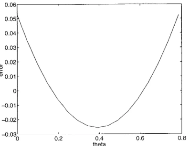
However, by using Equation 3.1, we must now compute jY[k]j. In floating-point front-ends jY [k]j2 is computed directly from the real and imaginary parts of Y[k] without computing IY [k] . Doing a fixed-point square-root is very difficult, so we use an approximation suggested in
[3,
6].x ~ amax(jR{x}, |G{x}|) + 3min(jR{x}|, 1!{x}j) (3.2)
To estimate a and 3 we use polar coordinates and minimize the distance between r and the estimate for jxj. For the following derivation we assume that the real part is bigger than the imaginary part. This narrows the range of 6 to 0 to i. If the opposite were true, swapping a and 3 would result in the correct approximation.
R{x} = r cos 0 £{x = r sin 6 min(r - (ar cos 0 + Or sin 0))2
a
= 2(-r sin0)(r - ar cos 0 - r sin 0) = 0
j
7/4 a d6 = -sinr +a (-0+ - sin 20 cos20}7r4 00 a 2 4 2 0
f
r/
4
a
d cos -co +/
7r/
dO = cos 0 - -Cos -0- - sin 20 0
o 0 2 (2 4 )0
a = 0.9475 =0.3925
The error for this approximation is given in Figure 3.1. In this figure the actual
magnitude has been held at 1, while the angle 6 was swung through 0 to *. The 4.
maximum error, achieved at 6 = 0 or 0 = 7, is .0525. The average value of the error 4,
is on the order of 10-4.
Thus, to compute the outputs of the Mel filter bank without overflow, we approx-imate the magnitude with Equation 3.2, multiply the magnitude by the root of the Mel filter parameters and square the outputs of the filters.
3.1.3
Natural Log and DCT
The computation of the natural log is another place where a new algorithm must be derived to handle fixed-point numbers. Because the representation of numbers in a computer is inherently binary, we choose to implement a fixed-point log base-2 and then scale by ln(2) to arrive at the natural log. This base-2 log algorithm was used in [3] and developed by [1]. The algorithm follows.
0.06 0.05 0.04- 0.03- 0.02-ID 0.01 - 0- -0.01- -0.02--0.03' 0 0.2 0.4 0.6 0.8 theta
Figure 3.1: Plot of error versus angle for magnitude approximation when actual magnitude is held constant at 1.
" Find the position of the leftmost 1 when the number is represented in binary.
The lowest order bit is position 0. Let that position be b
" Interpret the three bits to the right of position b on their own. Call this number
n.
" The approximation for the log is 8b + n in Q3
Here is an example using the number 50. The log base-2 of 50 is 5.644. We represent
50 in binary as 00110010. b for 50 is 5 since the leftmost 1 is in position 5. The next
three bits after position 5 are 100 thus n = 4. Our estimate for the base-2 logarithm of 50 is 44 in
Q3
or 5.5 in Q1.The DCT remains the same with all the necessary cosine values precomputed-computed, translated into fixed-point and cached.
3.2
Testing Conditions
The recognizer used for all of the experiments is part of the JUPITER system. JUPITER
provides various weather information such as forecasts, temperatures, wind speeds, and weather advisories for over 300 cities around the world [22]. It is accessible via a toll-free number, and all conversations are recorded for research endeavors. Utterances are transcribed on a regular basis and are added to the training corpus, saving a few for testing purposes. All the utterances then in the training and test
corpora are telephone quality recordings. The test set we used consisted of 1711 utterances deemed clean by the transcriber. The training set consisted of about
120,000 utterances whose MFCCs were computed with a floating-point front-end. Although the iPAQ was perfectly capable of recording utterances computing fixed-point MFCCs and transmitting them to the server for recognition, not enough data from the iPAQ was available to make a reliable training set. Creating a test set that used iPAQ recorded data also did not make sense because of the mismatch between the 16KHz iPAQ recorded test set and the 8KHz telephone recorded training data. Thus all the experiments done using the fixed-point front-end were performed in a simulated distributed environment, using telephone recorded speech and running it through the fixed-point front-end.
3.3
Results
Most of the work from this chapter was done in implementation of the fixed-point front-end. There are, however, several metrics we can look at to examine how this front-end compares to the floating-point front-end. One important metric is looking at the word error rates generated by each. Another way to compare the two front-ends is to look at the computation and storage costs associated with each.
3.3.1
Word Error Rate
One expects that because we are discarding information about the speech by doing fixed-point processing, word error rates would increase. However, we found that error rates actually improved. The error rates for the baseline floating-point front-end was
9.8%, and the fixed-point front-end recognizers had a word error rate of 9.6%. To
compare the performance, we performed a matched-pair sentence segment significance test. In a matched-pair sentence segment significance test segments of utterances which contain at least two consecutive words both systems recognized correctly. It, then, computes the difference in the number of errors made by each system [15]. The significance test found that the difference between the fixed-point front-end system and the floating-point front-end system was not significant. These recognizers used models trained on clean telephone speech processed by a floating-point front-end. We also retrained our models using the fixed-point features and saw no increase in performance by doing so.
3.4
Discussion
Our results show that using the fixed-point front-end improves the performance of the recognizer. We feel this could be because the fixed-point front-end gives an approxi-mation of the coefficients, and is, therefore, not as sensitive to the minor fluctuations in them that could affect recognition. In Chapter 4 we see similar results: as we quantize the coefficients, we can achieve better recognition rates over the baseline.
The system presented here is still far from complete. At this point the system can record data on the iPAQ, quantize it (as discussed in Chapter 4), and send it to the server for recognition, but the recognizer still uses models trained on telephone speech, so there is a fundamental mismatch between the test utterances and the models. Although retraining our models on fixed-point features did not improve recognition, collecting a large corpus, recorded on the iPAQ, is still needed so that an iPAQ recognizer may be built that will achieve comparable recognition rates to the simulations done here. Additionally at this time there is no response sent back to the iPAQ from the recognizer. Having either text or speech response would complete the system.
Chapter 4
Quantization of Mel Frequency
Cepstral Coefficients
Quantization
is a necessary part of any distributed speech recognition system. The bit rate of the system that does not do any front-end computation on the iPAQ is 64Kbps (8 bits p-law sampled at 8KHz) or 128Kbps (8bits p-law sampled at 16KHz for wide-band speech). Without quantization of the MFCCs the bit rate of the fixed-point system is 89.6Kbps (14 32-bit integers every 5 ms). In this chapter we will show the methods and results from both scalar and vector quantization of MFCCs.4.1
Quantizer Design
We chose to experiment with non-uniform scalar and vector quantizers. In this sec-tion we will discuss how we did bit allocasec-tion for both scalar and vector quantizers, effectively choosing the number of levels of the quantizer. We will also discuss how the subvectors were chosen and how the quantizer was actually created.
4.1.1
Bit Allocation for Scalar and Vector Quantization
The bit allocation scheme for both our scalar and vector quantizers is basically the same. One could see the scalar quantizer being a special case of the vector quan-tizer where each subvector consists of just one parameter. The greedy algorithm is described below.
" Initialize: For each subvector allocate one bit per coefficient in that subvector. " Iterate: Add one bit to subvector i, compute the word error rate for the given
* Assign: Assign one bit to the subvector that resulted in the lowest error rate. If desired number of bits or error rate is reached, quit. Otherwise return to Iterate step.
There is one case where this algorithm fails. That is when the lowest error rate occurs at more than one bit allocation. In the scalar quantization case we always add the bit to the lowest order coefficient. In the vector quantization case the bit went to the subvector that had the lowest number of bits at present. In addition to limit computational complexity in the scalar case, we capped the number of bits any coefficient could have at 8 bits. In the essence of speed, in the vector case we allocated two bits at a time in the vector case until a total of 30 bits had been reached.
4.1.2
Choosing Subvectors for Vector Quantization
Before we can allocate bits to subvectors, we must choose which coefficients go into each subvector. We used two methods of partitioning: a correlation-based method and a knowledge-based method. Correlation-based methods are methods that partition into subvectors based on information contained in the correlation matrix. Knowledge-based partitioning puts consecutive coefficient together. In this way the more impor-tant lower-order coefficients are kept together.
We used several methods to come up with an appropriate subvector using the correlation matrix. The first method progressively adds subvectors together based on the average correlation until the desired number of partitions is reached. This process is illustrated in Table 4.1. We start by having 5 subvectors. We find the two most correlated coefficients and put them in a subvector together to yield a partition of 4 subvectors. To compute the correlation between groups that contain more than one coefficient, the average of all the pairwise correlations of all coefficients in each group was computed. As shown in Table 4.1, to find the correlation value between coefficient 1 and the group
{4,5},
we averaged the correlations between 1 and 4, 1 and5 and 4 and 5((.3+.1+.8)/3 = .4). This method was used to develop the subvectors
for partition I shown in Table 4.2.
A second method used a set of coefficients as bases for each subvector then
clus-tered the remaining coefficients to the base with which it was most correlated. For example, if we wanted 5 subvectors, we would find the 5 least correlated coefficients
by first finding the first pair (just the pair with the lowest correlation coefficient) then
adding one coefficient to the set of bases by choosing the parameter that increased the average pairwise correlation in the set the least. Specifically, let each coefficient be represented by xi and the set of all coefficients be X. Let the current base set be B where each base coefficient is represented by bj, the size of B is n - 1 and (A, B) is the average of the pairwise correlations between all elements of A and B. Then it
1 1 .6 .4 .3 .1 2 1 .4 .2 .4 3 1 .1 .2 4 1 .8 5 1 11 2 3 4,5 1 .6 .4 .4 2 1 .4 .467 3 1 .367 4,5 1 1,2 3
j4,5
'12 1 .467 .4 3 1 .367 4,5 1Table 4.1: Progression of correlation relation based subvectors.
matrices for the first method of obtaining
cor-Label Subvectors Method
I [0,1,10,11,12,13], [2,3,5,6],[4,8],[7],[9] Correlation
II [0,1,6,71,[2,3,51,[4,8],[9,10],[11,12,13] Correlation
III [0, 1] , [2,3] , [4,51 , [6,71 , [8,9] , [10, 11] , [12,13] Knowledge
IV [0, 11 , [2,3] , [4,5,61 , [7,8,91 , [10, 11, 12, 13] Knowledge
Table 4.2: Subvector Partitions for VQ experiments.
can be said that
xi =- b,, if (xi, B) < (xj , B) Vxj c X \ B
This process of adding parameters to the base set was continued until the size of B reached 5. Now we thought of each base coefficient as the seed for a subvector. We went through each coefficient not included in the base set and assigned them to the subvector with which it had the highest average pairwise correlation.
add xi to bj if (xi, bj) > (xi, bk) Vbk E B
Using this method to come up with a correlation-based partition led to the creation of partition II shown in Table 4.2
In addition to using information obtained from the correlation matrix, we also tried knowledge-based partitioning. In these we simply grouped the coefficients in their numerical order to create subvectors. Two knowledge-based partitions were explored they are given in Table 4.2 partitions III and IV. Partition III simply used pairs of coefficients as subvectors. This partition is different that the others because it uses 7 subvectors. All the other partitions use 5 subvectors. Partition IV was similar to partition III except there are 5 subvectors of varying dimensionality.
40 35- 30- -25- '220-0 15- 10-2600 4000 6000 8000 10000 12000 bit rate
Figure 4.1: Plot of Scalar Quantization versus Vector Quantization.
4.1.3
Quantizer Creation
In order to create a non-uniform quantizer, we needed information about the statistics of our MFCCs. We created a random subset of 25000 utterances and computed the MFCCs for each. For scalar quantization then we merely ordered each coefficient and created equal probability bins by putting the same number of seen coefficients in each bin. For vector quantization we use binary splitting with k-means as described in Section 2.4.2.
4.2
Results
When comparing quantization schemes, we looked at two aspects: resulting word error rates and computational and storage costs. Here, we compare word error rates from the above bit allocation algorithm for both scalar and vector quantization. In order to choose a reasonable quantizer for the iPAQ, we must also look at the load it puts on the device, so we explore the computational and storage costs for the given quantizers.
4.2.1
Word Error Rates
In Figure 4.1 we show the results from the scalar quantization scheme and one vector quantization scheme. The vector quantizer shown here is partition I, but is represen-tative of all of the vector quantizers used. One can see that the vector quantization scheme achieves convergence at a lower bit rate than the scalar quantizer. The bit
Scalar Quantization
Bit Rate Bit Allocation Word Error Rate 4000 2 2 2 2 2 2 1 1 1 1 1 1 1 1 30.4% 5000 2 2 3 3 2 2 2 2 2 1 1 1 1 1 18.3% 6000 2 2 3 3 3 3 3 2 2 2 1 2 1 1 14.4% 8000 4 4 4 4 3 4 3 2 2 3 2 2 2 1 10.5% 9600 4 7 4 5 4 4 3 2 3 4 2 2 2 2 10.0% 11200 4 8 5 5 6 5 5 3 3 4 2 2 2 2 9.8%
Table 4.3: Bit rates, Allocation and corresponding Word Error Rates for Scalar Quan-tization.
rates, word error rates, and bit allocations for scalar quantization are given in Ta-ble 4.3. For this system the baseline floating-point recognizer has a word error rate of 9.8%. The fixed-point recognizer (with no quantization) also has a word error rate of 9.6%. It is interesting to note that with scalar quantization we can reach rates of
9.8%. Again we performed a matched-pair sentence segment significance test
[15].
It found that the difference between the fixed-point front-end recognizer and the scalar quantized MFCC recognizer was insignificant. We must also point out that ourSUM-MIT recognizer has a frame rate of 200 Hz which is uncommon. Most recognizers use
a 100Hz frame rate and thus the bit rate would be half what is recorded here. For the four vector quantization schemes Table 4.4 shows their resulting word error rates at different bit rates. We did not attempt as high bit rates in the vector quantization schemes as in scalar quantization because of the computation and storage costs. However, for the rates explored they all performed equally or better than scalar quantization. We performed a matched pair sentence significance test to compare partition II and partition III
[15].
It found that at 8000 bps the recognizers were insignificantly different. Unlike in Digalakis, et al. [4], since the knowledge-based partition was not significantly better than the correlation-based one, we found no appreciable difference between them for product-code vector quantization. Moreover, when we retrained our models using the quantized MFCCs, we saw no improvement.4.2.2
Computational and Storage Costs
To effectively compare the different quantization schemes presented in this chapter, we must also consider the computational and storage costs associated with each. In Section 2.4.2 we give equations to estimate of the computational and storage costs associated with different quantizers. Here, all of our vector quantizers are product code quantizers implemented with binary splitting. Since we perform an
![Figure 1.1: Real-time factors for each version of front-end code from [3].](https://thumb-eu.123doks.com/thumbv2/123doknet/14751874.580569/15.918.319.609.147.377/figure-real-time-factors-version-end-code.webp)
![Figure 1.2: Diagram of of IS-641 Encoder and Decoder with locations where features are extracted labeled with Cx from [11].](https://thumb-eu.123doks.com/thumbv2/123doknet/14751874.580569/16.918.237.772.137.255/figure-diagram-encoder-decoder-locations-features-extracted-labeled.webp)