Discrete Robotic Construction
by
William Kai Langford
B.S., Tufts University (2012)
M.S., Massachusetts Institute of Technology (2014)
Submitted to the Program in Media Arts and Sciences,
School of Architecture and Planning
in partial fulfillment of the requirements for the degree of
Doctor of Philosophy
at the
MASSACHUSETTS INSTITUTE OF TECHNOLOGY
September 2019
© Massachusetts Institute of Technology 2019. All rights reserved.
Author . . . .
Program in Media Arts and Sciences,
School of Architecture and Planning
August 9, 2019
Certified by . . . .
Neil Gershenfeld
Director, MIT Center for Bits and Atoms
Thesis Supervisor
Accepted by . . . .
Tod Machover
Academic Head, Program in Media Arts and Sciences
Discrete Robotic Construction
by
William Kai Langford
Submitted to the Program in Media Arts and Sciences, School of Architecture and Planning
on August 9, 2019, in partial fulfillment of the requirements for the degree of
Doctor of Philosophy
Abstract
Robots, which require the integration of a wide variety of mechanical and electrical functionality, are seldom built in a single process, but are instead assembled from parts created using a variety of different processes. While fabrication has advanced significantly to enable the routine fabrication of complex and precise objects from computer designs, the assembly processes used to integrate these parts are still largely manual and are notoriously difficult to automate. Recent research in digital fabrication has looked for ways to avoid assembly altogether by manufacturing integrated devices in a single process but has often struggled to integrate more than a few materials or functionalities. Instead of avoiding assembly, this work embraces it. Inspired by the universality of amino acids that are the basis of molecular biology, I demonstrate an interchangeable set of building blocks that enable the construction of a wide variety of robotic capabilities, including machines that can assemble themselves. In this thesis I introduce a discrete approach to robotic construction that enables the fabrication of structure, mechanism, actuation, circuitry, and computation in a single process through the assembly of a small set of building blocks. This work is based on discretely assembled “digital” materials, in which parts are reversibly joined with a discrete set of relative positions and orientations, allowing for global geometries to be determined from local constraints, assembly errors to be detected and corrected, heterogeneous materials to be joined, and disassembly and reuse rather than disposal. This approach simplifies the fabrication of integrated electromechanical machines and points to the possibility of building technology that is able to grow (exponential self-assembly) and self-repair. Furthermore, this approach discretizes robotic systems at a finer granularity than prior work in modular robotics, offering benefits including the flexibility to integrate heterogeneous functions, agility to rapidly construct and modify designs, and incremental extensibility in both system size and performance. These benefits help lower barriers in the rapid prototyping of electromechanical machines, make designs more reusable by providing a physical representation that facilitates design automation and abstraction, and enable machines that are more integrated than would be practical with alternative methods.
Thesis Supervisor: Neil Gershenfeld
Discrete Robotic Construction
by
William Kai Langford
This dissertation/thesis has been reviewed and approved by the following committee members
Sangbae Kim . . . . Associate Professor of Mechanical Engineering Massachusetts Institute of Technology
Discrete Robotic Construction
by
William Kai Langford
This dissertation/thesis has been reviewed and approved by the following committee members
Jennifer Lewis . . . . Hansjorg Wyss Professor of Biologically Inspired Engineering Harvard University
Acknowledgements
I’d like to acknowledge of the people who helped and supported me in this work. I wouldn’t have been able to do it without you all.
Thank you to my committee members – Sangbae Kim and Jennifer Lewis – for taking time out of your very busy schedules to meet with me and to help me think through outcomes of this work beyond CBA’s research roadmap.
I’d like to thank my advisor, Neil Gershenfeld. I certainly could not have done this work anywhere else. You’re unwavering vision for the work we do is inspiring. Thank you for showing me a new way to look at the world. I’m certain that I will never again have access to quite the same level of resources again. Being able to design something in the morning, go to the shop in the afternoon, run jobs on the wire-EDM, precision CNC mill, and multiple 3D printers (all simultaneously), and then have a first prototype by dinner is a very special kind of power that I know I’ll miss.
However, the tools are not nearly CBA’s greatest feature. It is it’s people. In the seven years that I’ve been here I’ve made great friends and had the opportunity to work with amazing collaborators. I first want to thank the CBA staff – Joe, James, Kara, Jamie, John, Tom, and Ryan – not just for their support in managing projects, putting in orders, and doing all the behind-the-scenes work that makes our research work possible, but also for getting lunch, hanging out, and creating a sense of community.
I’d like to thank all of the CBA students – Sam, Prashant, Ben, Amanda, Grace, Jake, Sara, Erik, Amira, Filippos, Patricia, Noah, James, Nadya, Eric, Matt C., Matt K., and Kenny. I’ve learned so much just from being around you all for these years. Sam, in particular, thanks for our coffee-talks and whiteboard sessions.
I’d like to thank my friends and collaborators outside of CBA – Carlos, Jifei, Lining, Guillermo, and Sophia. In particular, Carlos, thank you for always making sure my priorities are straight with our weekly call (even when I’m “too stressed”).
Thank you Sherry and Neil for taking me on Fablab trips all over the world. It’s an amazing privilege to be able to travel to some of the coolest places in the world to help teach people about digital fabrication.
Thank you to the CBA UROPs – Uyen, Soma, Jason, Steven – for helping me experiment with ideas and being guinea pigs for my developing leadership and mentoring skills.
Thank you to my family – Mom, Dad, Ben, Grandma, and Oscar – for making me who I am today.
Contents
1 Introduction 15
1.1 Motivation . . . 15
1.2 Background . . . 18
1.2.1 On-Demand Fabrication of Robotic Systems . . . 18
1.2.2 Self Replicating Machines . . . 20
1.2.3 Biology . . . 21
1.3 Approach . . . 24
1.3.1 Implications . . . 24
1.3.2 Goals and Metrics . . . 25
2 Joints 27 2.1 Design Guidelines . . . 27
2.2 Interlocking Press-Fit Slots . . . 28
2.2.1 Electrical Characterization . . . 29
2.3 Alternative Joint Systems . . . 31
3 Structure 33 3.1 Lattice Structures . . . 33 3.2 Digital Materials . . . 34 3.3 A New Geometry . . . 35 3.4 Sizing . . . 36 3.5 Production . . . 37 4 Mechanism 39 4.1 Compliant Mechanisms . . . 39 4.2 Part Types . . . 40 4.3 Modeling . . . 40 4.3.1 Kinematics . . . 40
4.3.2 Quantization of a continuous range of transmission ratios . . . 42
4.3.3 Dynamics . . . 44
4.4 Production Methods . . . 45
5 Actuation 51
5.1 Actuation at the millimeter scale . . . 51
5.2 Electromagnetic Lorentz Force Actuators . . . 53
5.2.1 Modeling . . . 54 5.2.2 Experimental Characterization . . . 57 5.2.3 Production . . . 60 5.2.4 Discussion . . . 61 6 Walking Motor 63 6.1 Design . . . 63 6.2 Characterization . . . 63
6.2.1 Speed and Repeatability . . . 64
6.2.2 Force Additivity . . . 66
6.3 Discussion . . . 67
7 Walkers 69 7.1 Electropermanent Feet . . . 69
7.2 MOTILE – Modular Tiny Locomotion Element . . . 71
7.3 Discussion . . . 73
8 Positioning and Manipulation 75 8.1 Positioning . . . 75 8.2 Manipulation . . . 75 8.3 Discussion . . . 76 9 Circuitry 79 9.1 Background . . . 79 9.2 Routing . . . 80 9.3 Logic . . . 82 9.4 Control . . . 84 9.4.1 Control in struts . . . 84
9.4.2 Control between struts . . . 84
9.4.3 Redefining struts for greater routing density . . . 86
9.4.4 Tiles – Decoupling mechanical and electrical routing . . . 87
9.5 Production Methods . . . 88
9.6 Discussion . . . 91
10 Automation 93 10.1 Electronic Digital Material Stapler Assembler . . . 93
10.2 Design Overview . . . 93
10.2.1 Detailed Design . . . 94
10.2.2 Workflow and Characterization . . . 94
10.3 FABBR – Functional Assembler of Building Block Robots . . . 96
10.3.1 Design Overview . . . 96
10.3.3 Characterization . . . 99 10.3.4 Extensions . . . 101 10.4 Assembling Assemblers . . . 102 10.4.1 Current Limitations . . . 105 11 Scaling 107 11.1 Part Production . . . 107 11.2 Actuation . . . 108 11.3 Assembly . . . 110 12 Modeling 113 12.1 Modeling Approaches . . . 113 12.2 Optimization Approaches . . . 114
12.3 Compliant Mechanism Simulation and Optimization . . . 114
13 Applications and Extensions 117 13.1 Discrete Integrated Circuit Electronics (DICE) . . . 117
13.2 Relaxing Constraints . . . 119
14 Conclusion 123
Chapter 1
Introduction
1.1
Motivation
The design and fabrication of robots today can be expensive, time consuming, and inflexible. It often involves the integration of a wide variety of unique parts, each of which may be made using separate and unrelated processes. This assembly and integration step often represents the bottleneck in the time and flexibility in the development of a new robotic system [1] [2]. Achieving high performance often means designing from the ground up and fabricating a bespoke, application specific robot.
Researchers have looked at modularity as a way to increase the flexibility in the configuration of new robotic systems. By abstracting robotic capabilities to a small number of unique modules, a new robotic system can be configured and reconfigured to suit a particular task through the (relatively) simple arrangement of the modular parts. These modular parts, however, often end up needing to integrate actuation, sensing, communication, computation, and structure, and do so in a physically small volume. This results in modules that are expensive and difficult to manufacture, and ultimately limits the performance of the resulting robots made this way [3]. In doing so, the difficulty to develop a new robotic system has been reduced but at the expense of a simultaneous reduction in performance (Figure 1-1).
As a result, recent research in digital fabrication has looked to avoid the assembly and integra-tion step altogether by fabricating devices in a single monolithic process. This includes processes that assemble intricate mechanisms through the lamination of various pre-machined layers [8], the integration of hydraulic channels in additively manufactured robot limbs [9], and even the direct printing of entirely soft robots [10]. However, each of these processes still has inherent limitations including the kinds of materials it can work with, the dimensionality of the end-product (2D vs 2.5D vs 3D), and the dynamic range it can support (maximum size per minimum feature size). As a result, I argue that no one process will be able to span the full range of desired robotic capabilities. Biology offers an alternative inspiration. Rather than trying to integrate all of the desired functionality in a common process, it builds from a standardized set of building blocks that share a common interface. All of life is assembled from 20 standardized building blocks, amino acids (Figure 1-2). These building blocks are assembled one part at a time by a machine, the ribosome, which itself is made from the same building blocks. These biological assemblies are truly complex and integrated. They sense, actuate, move, flex, and act as structure and do so at a resolution
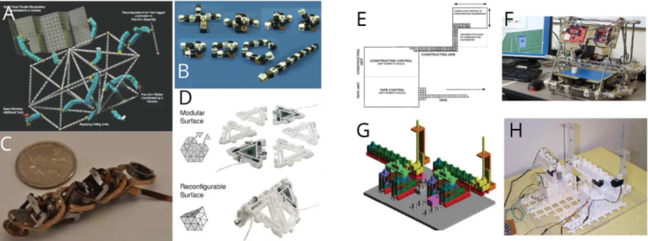
Figure 1-1: The robot design and fabrication space in terms of “configuration complexity” (number of unique parts) vs performance. Highly performant robots (C) are often bespoke and require ground-up design and development (1-4) [4] [5] [6] [7]. Modular robots (D) tend to tradeoff performance for versatility (1-3) [3]. Digital fabrication research (B) has looked for ways to avoid assembly by integrating functionality in monolithic processes (1-3) [8] [9] [10]. Biology (A) offers an inspiring alternative as it assembles all of life from (essentially) 20 building block parts (amino acids) (1-4) [11] [12] [13] [14].
and performance that far exceeds what we are currently capable of producing with human-made technology [15] [16].
Figure 1-2: The twenty amino acids that enable the assembly of biological systems do so through levels of hierarchy: primary, secondary, tertiary, and quaternary structure. The “engineering amino acids” should likely exhibit a similar structural hierarchy. Individual bulk-material building blocks assemble functional parts, functional parts assemble into modules, and modules then assemble into systems (1-2) [16] [17].
This leads to the question that prompted the work developed in this thesis: Can we develop a set of simple, functional parts that enable the assembly of a wide range of integrated machines? In this thesis I introduce a discrete approach to robotic construction that enables the fabrication of structure, mechanism, actuation, circuitry, and computation in a single process through the assembly of a small set of building blocks. This approach takes inspiration from the amino acid building blocks that are the basis of molecular biology and offers benefits in the integra-tion of heterogeneous funcintegra-tionality, agility in creating and modifying designs, and points towards the capability for technology to grow (self-assemble) and self-repair. Rather than avoiding assembly in pursuit of integrated manufacturing, this approach embraces it, and demonstrates that the inter-changeability of building blocks enables the assembly of a wide variety of capabilities from a small set of part types.
The approach I introduce is based on prior work in discretely assembled “digital” material systems. Digital materials are based on a discrete set of parts, which are reversibly joined with a discrete set
of relative positions and orientations [18]. These properties allow global geometries to be determined from local constraints, assembly errors to be detected and corrected, heterogeneous materials to be joined, and disassembly and reuse rather than disposal [19]. Digital materials have been used to produce the highest reported modulus ultralight materials [20], shape morphing structures with the use of rigid and flexural parts [21], as well as electronic structures with the addition of conductive and insulating parts [22] [23].
This approach builds systems with integrated structure, mechanisms, and actuation in a way that can be incrementally extended and modified. Standardizing the assembly interfaces between parts and simplifying the assembly process, to require just a single vertical motion, means the assembly process can more closely resemble a digital fabrication workflow and represents a significant step towards enabling on-demand fabrication of a wide-range of robotic systems.
1.2
Background
The approach introduced in this thesis works towards two active goals in the areas of digital fabri-cation and modular robotics: (1) on-demand fabrifabri-cation of robotic systems and (2) self-replicating machines. Additionally, this approach takes inspiration from the way that biological system manu-facture across scales (grow).
1.2.1
On-Demand Fabrication of Robotic Systems
The goal of simplifying the manufacturing of highly integrated machines and robots to enable on-demand fabrication of robotic systems has been explored from a number of different perspectives. These include folded and origami-based manufacturing methods, additive manufacturing and soft-robotics, as well as digital material assembly.
Figure 1-3: The goal of enabling on-demand robot fabrication has been approached by ways includ-ing: folding-based methods (A,B) [8] [24], soft robotics (C,D) [10] [25], and digital material (E,F) [26] [21].
Folding-Based Processes
Folding based processes look for ways to pattern functionality in a two-dimensional sheet and then fold to create a three-dimensional structure (Figure 1-3 A,B). These kinds of processes are well suited for on-demand robot fabrication because patterning and structuring two-dimensional sheets can be done quickly, precisely, and at a high resolution. These processes are often able to incorporate multiple materials to achieve various kinds of functionality within a single device. Whitney et al. demonstrated the assembly of complex mechanical linkages through the lamination of rigid and flexible layers [8]. Furthermore, an assembly scaffold, patterned along with the robot, was then used to coordinate the folding of the two-dimensionally patterned sheets into a three-dimensional robot, the Robobee. This approach has enabled the batch production of devices with a broad material set and a design flexibility that was previously inaccessible in millimeter-scale robotics. While these robots are still typically designed by hand, others have looked at the possibility of automating the design of folded robots [27]. The work of Onal et al. demonstrates how a library of design templates with parametric dimensions may be used to lower the barriers in the design and development of these robots [24]. Furthermore, these machines show the extent to which a single laser-cut shape can define complex three-dimensional body shapes and mechanisms.
While these folding processes are often able to incorporate both mechanical linkages and circuitry in a single process, actuation is typically integrated in a separate step. Onal et al., for example, attach off the shelf DC motors to the robot after it has been folded. In millimeter-scale laminate devices actuation often takes the form of a piezoelectric actuator that is made using a separate laminate process and assembled manually [28]. As these devices become more complex and integrate more functionality, the number of layers and process steps increases. Given the monolithic nature of these devices, an error in any single layer can ruin a whole device. As such, it is common for the designer to invest significant time upfront in the design of the device to ensure there are no errors, limiting the resulting turn-time and agility of the fabrication approach [27]. As a result, while monolithic designs could ultimately enable on-demand robot fabrication, practically, it often makes more sense to split a complex design into subsystems which are laminated and then integrated separately [28].
Additive Manufacturing and Soft Robotics
Recent efforts to integrate actuation into 3D printing workflows have seen promise in the direct printing of soft robots and actuators (Figure 1-3 C,D). By structuring geometry, hydraulic or pneu-matic forces can be converted into motion [29] [30]. These processes are able to produce devices with useful forces and motions in a nearly monolithic process. While these robots have been tra-ditionally made with molding processes, more recent research has demonstrated the possibility of directly printing these kinds of soft robots and machines [10] [25]. These soft machines have a range of useful applications and are often applicable in scenarios that are not well served by traditional “hard” robots.
While these processes greatly extend the capabilities of robotic fabrication, they are still limited in the kinds of materials and functionalities that they can integrate. The material set is often limited by the requirements of the deposition processes, which constrains the range of functionality and, as a result, the potential applications. Furthermore, the scarcity and properties of compatible soft-materials limits the available functionality below the millimeter scale [31] [32].
Other research has looked at ways to directly print hydraulic actuators for use in high-performance robots such as Boston Dynamic’s Atlas robot [9]. These actuators are able to unify what used to be several separate components. But beyond hydraulic actuators, this process doesn’t likely scale to include other kinds of functionality like electronics or large displacement compliant joints. Digital Materials
Discretely assembled “digital” material systems are another avenue that has been explored towards the goal of enabling on-demand robot fabrication. Digital materials are a discrete set of parts, which are reversibly joined with a discrete set of relative positions and orientations [18]. These properties allow global geometries to be determined from local constraints, assembly errors to be detected and corrected, heterogeneous materials to be joined, and disassembly and reuse rather than disposal. The building block parts that compose a digital material can be produced using a range of different processes and in a range of different materials. This enables the integration of diverse functionalities including structure [20], mechanisms [21], and electronics [22] [23] within a single assembly framework.
The prospect of using digital materials to enable on-demand robot fabrication has been explored in theory [33] [34] but physical implementations have largely relied on either slow global thermal actuation [33] or on off-the-shelf actuation components [23]. In a more recent study, Cramer et al. demonstrated very simple locomoting robots made through the actuation of deformation modes of a discretely assembled lattice using commercially available linear servo motors [26] (Figure 1-3 E).
1.2.2
Self Replicating Machines
The idea that modular building blocks can be used to assemble self-replicating systems is not a new one and has been explored computationally since at least the 1940’s. At that time Von Neumann developed the concept of a universal constructor, built around a set of cellular automata rules, that can construct itself and pass on a blueprint for further self-replication [35]. For a number of reasons, Von Neumann’s concept is not particularly physically realistic. For example, blocks are not translated but rather destroyed at one location and created at another. However, others have built on Von Neumann’s original idea and developed versions of the universal constructor that are more physically-based [36]. These ideas are still very far from a physical embodiment but demonstrate that a self-replicating machine is kinematically feasible. Researchers as recently as 2016 have written papers entitled, “Are Self-Replicating Machines Feasible?” [37], clearly showing the disparity between theory and practice. This more recent research still concludes that self-replicating machines are feasible, but notes that there are a number of practical barriers that must be overcome first. Modular Robotics
Work in the field of modular and reconfigurable robotics has looked to address the challenges of self-replication by simplifying the feedstock to a set a of modular building blocks [42] [43] [40]. These systems typically integrate actuation, controls, communications, and structural connections within modular units, which are then configured (and reconfigured) to suit a particular task. While these systems illustrate the universality of a small number of modular building blocks, the resulting modules are relatively complex, involve dense integration of the various functions, and tend to be
Figure 1-4: Modular robotic systems are configurable and capable of adapting to a variety of different applications. They may be used as manipulators to assemble truss structures [38]. Modular chain robots [39] [40] and surfaces [41] can be contorted and twisted to form a variety of shapes and structures.
expensive to fabricate in volume. As a result, they have typically found limited utility outside of the research lab.
In-Situ Resource Utilization (ISRU) Approaches
These self replicating machines are being pursued for a number of different applications, one of which is space exploration and development. The development of in-space manufacturing capabilities and modular robotics architectures are important steps towards self-replicating systems. Research in self-replicating hardware is in early stages and most prior work addresses high-level system design challenges including hierarchy and scale [44] as well as required ISRU capabilities and launch require-ments for self-sustaining factories [45]. Other prior work has looked at lower-level implementation details and established methods of creating self-replicating systems with macroscale building blocks. Moses et al. built a universal constructor system, for example, using 18 part-types that is capable of assembling some of its own subsystems [46]. However, the parts have a high-degree of embedded complexity, including conventional actuators and processors, which limits the potential scalability of such a system.
1.2.3
Biology
Ribosomal Assembly (Growth)
Ribosomal assembly, or growth, is able to achieve a wide dynamic range between the size of the parts and the size of the assemblies because of error correcting processes during part assembly and because of its self-replicating machinery that enables an exponential ring-up in manufacturing capacity (ribosomes assemble ribosomes).
Amino acids are often referred to as the building blocks of life [15] and make up, when assembled as proteins, approximately 60% of the dry mass of mammalian cells. They are made up of a common backbone, which allow them to bond to form a string, and a side chain, which confers simple chemical, structural, or functional properties to the part such as hydrophobic/hydrophilic or basic/acidic.
These twenty standard L-α amino acids, each with unremarkable properties on their own, are the building blocks that enable the assembly of all biological machinery, including a machine that can make itself, the ribosome. Ribosomes assemble amino acids at relatively unremarkable rates, ranging from 0.6 Hz to 20 Hz [47], but each cell may contain upwards of 72,000 ribosomes (in fast growing E. Coli), representing one third of the cell’s dry mass and a volumetric density of approximately 50,000 per cubic micrometer [15]. The tens of trillions (1013) of cells in the human body, each containing, on
average, a few billion proteins (109), which are themselves made up of a couple hundred amino acids
(102), means we are made up of approximately 1026 parts [15]. In comparison, the largest dynamic
range (minimum feature size to build area) of our most advanced manufacturing techniques is only about 1013 (Nanoscribe [48]). This kind of complexity is made possible in reasonable time-scales
not because ribosomes are fast (they assemble at approximately 1 Hz), but because ribosomes can assemble ribosomes, enabling massively parallel assembly.
Beyond the ability of ribosomes to assemble ribosomes, another critical aspect in being able to span large dynamic ranges in a single process is error correction. Before the mRNA instruction set reaches the ribosome, it has already gone through multiple stages of error correction and proofreading through the transcription process. During and after translation of the mRNA into the peptide chain, another set of error correcting steps is taken to discard, degrade, and recycle incorrectly translated proteins. Transcription has been reported to have error rates on the order of 10−5 while translation
error rates are an order of magnitude more, or 10−4 [49] [15] [50].
Figure 1-5: Biological machines exhibit modularity and reusability. The same motor proteins (A) [15] and microtubules (D) [51] that help organize the cell (B,C) [52] [53] are also used to actuate flagella mechanisms of swimming sperm (E) [13]
.
Amino acids enable the assembly of highly capable machines and behaviors. The proteins as-sembled from amino acids are present in a wide range of sizes but have an average length of approx-imately 400 amino acids in eukaryotic cells [15]. As the protein’s primary structure is being formed through translation of mRNA by ribosomes, it folds into a three-dimensional structure based on hydrophobic/hydrophilic interactions, molecular chaperones, and environmental conditions such as pH. The structure of the protein exhibits hierarchy and its functionality and geometric motifs can be grouped into primary, secondary, tertiary, and quaternary levels [16]. These proteins are then used as building blocks for a wide variety of cellular mechanisms and behaviors including structure, elasticity, transport, and signaling [54]. Furthermore, as a result of assembling all of life from the
same twenty building blocks, biological assemblies end up having a great deal of modularity and reusability across a number of different applications. The same kinds of microtubules and motor proteins that organize cells and give them their structure are also used to actuate flagella to propel swimming organisms like sperm [13] (Figure 1-5).
Manufacturing Across Scales
Treating ribosomal assembly like a manufacturing process, it is possible to compare our existing manufacturing methods and see that all fall short of the precision, resolution, and complexity of biological assembly. In Figure 1-6 I present estimates of the resolution and throughput of ribosomal assembly in biological systems. These estimates should be viewed as establishing orders of magnitude rather than precise measured quantities. For each biological system I estimate the number of amino acids that compose all of the proteins that make up that specimen. For the three mammals presented (Mouse, Human, Blue Whale), I estimate amino acid content based on a protein fraction of their dry mass (60%) and assume a dry mass fraction (30%) of their total mass. I do the same for C. Elegans noting that the protein fraction is closer to 55% of their dry mass. HeLa cell, E. Coli, and Eukaryotic protein estimates are based on protein counts reported in literature combined with average protein length in Eukaryotes (400aa) [15]. In all of the above I assume that growth rate is linear with time, which will both overestimate and underestimate growth at certain development stages but therefore represents a reasonable average.
I do the same for manufacturing techniques including discrete assembly, additive manufacturing, and state of the art conventional assembly, estimating the effective number of resolvable elements and the throughput at which those elements can be assembled.
Figure 1-6: Manufacturing throughput vs dynamic range for across manufacturing processes. Biol-ogy’s throughput scales with the size of the manufacturing problem and enables the fabrication of organisms with far more fabrication complexity than any state-of-the-art technological process.
throughput and complexity of a human cell. Beyond that, there is no technological fabrication process that can extend into the space that biology occupies. We (humans) are made from on the order of 1026amino acid parts. While our fabrication capabilities let us span from tens of nanometer
silicon chips to hundreds of meter long aircraft, we do so in discontinuous processes with no shared representation. And it is the discontinuities in this approach that I argue largely limit the flexibility of manufacturing.
1.3
Approach
This thesis attempts to address the question: can we develop a set of simple functional parts that enable the assembly of a wide variety of integrated machines?
The hypothesis is that by standardizing the interfaces between parts, the assembly process can be treated like a digital fabrication process. Furthermore, by discretizing functionality at such a fine level, we can enable much tighter integration and coupling between functionality that is typically separate in conventionally made robotics. This merging of functionality represents a unified approach to robotic construction that could also help lower the barrier to things that are not yet possible, like machine self-replication.
In this thesis I focus on the development of capabilities necessary to build assemblers that can assemble assemblers. This application serves both as a case study for integrating various robotic func-tionalities within a machine, and represents the direction toward massively-parallel high-throughput assembly. In order to build assemblers that can assemble assemblers there are a number of capabili-ties that are needed and steps to achieve. The assembler will need to integrate structure, mechanism, actuation, circuitry, and computation. The following chapters will describe the design of the building block parts and how their arrangement enables the assembly of these various capabilities.
1.3.1
Implications
This work impacts the way in which robotic systems are designed and fabricated today and helps pave the way towards future goals such as high-resolution on-demand fabrication of robotic systems and self-replicating machinery. Specific implications of this work include:
• Treating assembly like a digital fabrication process. This work shows that by standard-izing assembly interfaces, the assembly and configuration of functional systems can be treated like a digital fabrication process, enabling on-demand fabrication of robotic systems.
• A unified approach to robotic construction enables a tighter coupling between structure, mechanism, actuation, circuitry, and computation. By discretizing at a fine-grained functional level, capabilities that are typically distinct can be merged much more densely in this approach. Circuits can be routed through structural volumes, actuated degrees of freedom can be distributed rather than centralized, and computation and control elements can be spatially distributed closer to the components they drive.
• A new way of digitally fabricating integrated machines and robots with a un-matched range of functionality. Rather than trying to integrate multiple functionalities in
Figure 1-7: The approach explored in this work represents a unified approach to robotic construc-tion. Conventional machines integrate diverse functionalities without any standardization and are often bottlenecked by boundaries between functionality. Rather than integrating the fabrication of functionality within a single process [55] [56], this approach enables the assembly and integration of wide variety of parts, each of which can be made using separate and dedicated processes. “Separate” image from [57].
a single process, this approach is able to achieve an unmatched range of integrated functionality through the integration of parts made in a wide range of different processes.
• A viable way to close the fabrication complexity gap. This approach helps lower barriers to assembling assemblers and provides a viable way to increase the resolution and complexity of technological systems through recursive assembly.
1.3.2
Goals and Metrics
This work is guided by the following metrics:
Complexity The aim of this work is to enable the assembly of relatively complex devices from relatively simple parts. For this assembly approach to be interesting, the dynamic range between the complexity of the parts and the whole should be larger than existing work in modular robotics and much closer to the dynamic range (minimum feature size to work envelope) of an additive manufacturing process.
Universality An additional aim of this work is to show how a small number of building blocks can be combined to form a large variety of assemblies. This metric discourages special-purpose parts and emphasizes finding part types that play a number of useful roles in a system.
Performance Finally, the assemblies fabricated using this process should be useful and competi-tive with existing techniques for on-demand robot fabrication. Power density, specific stiffness, and fabrication time are criteria that are particularly relevant to this work.
In the following chapters I will discuss the components of this assembly framework: starting with and individual structural joint, and demonstrating the assembly of structure, mechanism, and actuation. Following that, I will demonstrate the assembly of machines that integrate these capabilities. From there, I will discuss the how circuitry and computation can be added to these assemblies, look at the automation and scaling of this work, and finally discuss future applications and promising results that are being explored.
Chapter 2
Joints
2.1
Design Guidelines
One of the most fundamental aspects of this work is the identification of interlocking joint systems that can be used to reliably and robustly join parts in this assembly framework. This is also one of the most challenging aspects of this work: finding functionally compelling joints that are simple and small enough to “disappear” in the structure. The assembly framework presented in this work does not presuppose any particular joint type but does seek a number of desirable traits:
• The parts should interlock mechanically. One of the fundamental takeaways in [58] was the observation that “To build strong structure from bricks, they should be interlocked. This gives the structure the strength of covalent bonding in at least some directions.”
• The joints should function both as a mechanical connection and electrical connec-tion. This work hinges on the idea that parts can serve a dual purpose, providing structure as well as electronic functionality simultaneously.
• The joints should be reversible. They should be capable of being removed and rejoined a number of times before failing. Generally electronic connectors are rated to maintain a certain connection resistance over a certain number of cycles [59]. The challenge is in designing the connector to not wear significantly with use but still achieve a reliable contact that is able to circumvent insulating surface oxides [60].
• The joints should be geometrically small and simple. Because each part will feature at least two (and likely more) joints, the volumetric overhead of the joints adds up very quickly. • The joint should have some degree of error correction or self-aligning features. Features that help guide the assembly reduce the precision required by the assembly machine (or person).
• The joint should be easily “automatable.” For example, joining with only a single degree-of-freedom motion and not requiring the coordination of multiple end-effectors.
2.2
Interlocking Press-Fit Slots
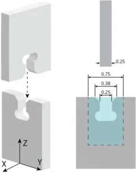
Based on these desirable traits, I selected a simple interlocking press-fit slot as the best suited joint system (Figure 2-1). The connection between parts is made with two orthogonal interlocking slots that are toleranced to be a tight fit with one another. This joint works well for this application first and foremost because it is geometrically small and simple. The geometry takes up a volume of 3t × h/2.1 × t given part thickness, t, and part height, h.
Figure 2-1: Interlocking Press-Fit Slot Design. The blue region indicates the area taken up by the single joint.
Cutouts at the bottom of the slots (often referred to as “dog-bone cutouts”) are required to ensure that the parts can fully seat. Without the cutouts the radiused cutting tool (in this case the 0.23 mm kerf width of the Wire-EDM) will leave a radius in the corner of the slot and not allow the full insertion of the parts.
The length of the slot is chosen to be as long as possible with respect to the part geometry. In this case that length is slightly less than one quarter of the part-height, h. The length of the slot provides rigidity against torques about the X and Y axes. Rigidity against torques in the Z-axis is improved with an increase in the thickness of the parts.
The joints feature chamfers on the edge of the part geometry to aid in the relative alignment between mating parts. The chamfers are dimensioned to accommodate translational errors in X or Y assembly axes of up to ±190 µm.
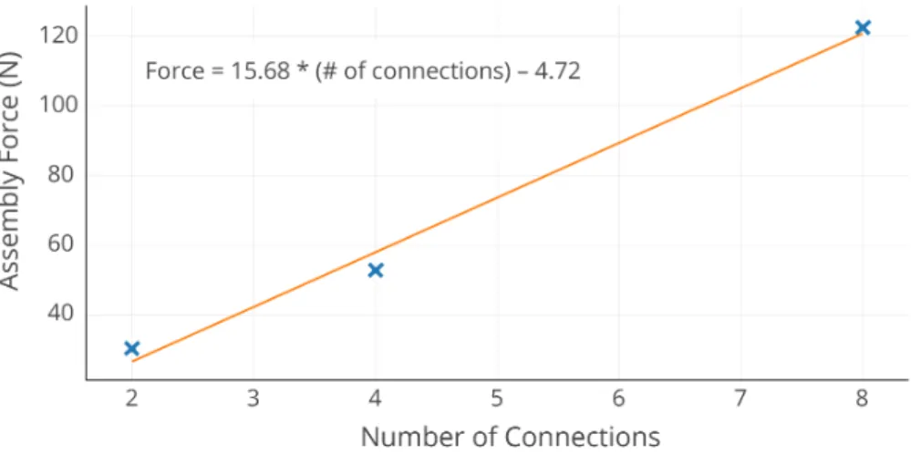
The force required to insert a part scales with the number of simultaneous interlocking interfaces. For the parts used in this work, which are 250 µm thick and made of phosphor bronze, approximately 15 N of force is required per joint interface to insert (Figure 2-2). Because of the symmetry in the interlocking slots, the joint requires approximately the same amount of force to remove as it does to attach. This means these joints can resist tensile forces up to this insertion force.
Figure 2-2: Assembly force is proportional to the number of simultaneous joints being made (15.7 N per joint).
2.2.1
Electrical Characterization
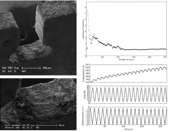
In my Master’s thesis I characterized the electrical conductivity of these kinds of press-fit joints [61] (Figure 2-3). I’m including a summary here for completeness and convenience.
The joints are reversible meaning that the parts can be joined and unjoined a number of times while still maintaining a low contact resistance. To measure this, I constructed a machine that can join and un-join the parts rapidly and measure the resistance across the joint using a sensitive four-wire measurement. In their joined state, the parts are preloaded with a constant force spring. What I found is that the contact resistance is initially somewhat variable and then settles after a few cycles to a low (≈ 1 mΩ) contact resistance.
Load cycling of a sample containing many joints led to an overall increase in conductivity. An electron micrograph of the surface revealed the likely cause of this conductivity increase was the flattening of surface asperities, effectively increasing the contact area.
Surface Preparation
Surface quality and preparation plays an important role in the development of good electrical con-tacts. It’s common practice in the design and manufacturing of electrical contacts to plate the contacts with metals that form good electrical contacts. These metals are often soft (have low hardness), have high conductivity, and do not form hard oxide layers.
I tested an assembled sample before and after copper electroplating to determine its impact on the electrical conductivity of the sample. The assembled sample is composed of two nodes and three struts. The sample measures 20 mΩ using a 4-wire resistance measurement (measuring from outer strut to outer strut). This resistance is composed of two components: bulk resistivity of the bronze parts and the contact resistances of the joints. I can very roughly approximate the resistance due to the bulk resistivity of the parts by integrating the resistivity over the volume of the parts with the equation: R = ρL/A. Based on this, I should expect the contribution of the bulk resistivity to be approximately 1 mΩ, much less than the 20 mΩ that I measured. This indicates that, unsurprisingly,
Figure 2-3: (Left) A scanning electron micrograph of an interlocking slot after having been used. Flattening of surface asperities is visible on the side of the slot walls. (Right-Top) The joint is reversible and has a 1 mΩ contact resistance even after 500 cycles. (Right-Bottom) Load cycling a structure composed of joints works to increase the conductivity of the bulk specimen.
the contact resistances contributes significantly to the resistance of the sample.
To account for the individual contact resistances within the sample it’s important to have an idea of which resistances are in parallel and which are in series. Imagining the path of an electron through the the sample, I constructed an equivalent circuit to determine how the overall resistance is summed from the individual contact types (strut-node and node-node).
To determine the contribution of contact resistance on the overall resistance, I electroplated the specimen with copper (10 minutes at 200 mA). The idea being that the thin layer of extra copper has a negligible effect on the bulk resistivity but bridges the small gaps at the joints between parts, drastically reducing contact resistance. In fact, after electroplating, the resistance across the structure measures 1 mΩ (±1 mΩ).
Using electroplating to post-process assemblies is potentially possible but not ideal since it does not align well with the idea that discrete assembly can be a digital fabrication workflow. Instead, it is possible to just electroplate node parts prior to assembly and achieve many of the same benefits. Electroplating just the nodes (for 12 minutes at 50 mA) reduces the resistance of the assembled test structure to 1.5 mΩ (±1mΩ), roughly same as the fully electroplated sample.
2.3
Alternative Joint Systems
While I selected the interlocking slot joint system as the most suitable to develop the functionality that I sought in this assembly framework, other joint types could certainly be worth exploring in more depth. Here, I’ll give a cursory overview of some of the other joint types I’ve considered and their relative merits.
“Snap-lock” This joint is very similar to the press-fit slot but includes cutouts on either side of the slot to allow for the creation of flexural “snap-lock” features. This joint system allows for the possibility of tuning the insertion and removal force separately, potentially enabling a very low force insertion but high force removal. This joint suffers two primary downsides. For one, the cutouts on either side of the slot increase the size of the joint, certainly increasing the width of the joint by more than four times the minimum feature size of the manufacturing process (since a slot needs to be cut on either side of the flexure). For parts already produced at the minimum feature size of a process (where δkerf ≈ t), this increases the width of the joint by more than 2 times
(3t + 4δkerf ≈ 7t, 7/3 = 2.33). The second major downside is that these flexural cutouts greatly
reduce the torsional stiffness of the joint. While it may be possible to include geometric features that help address this concern, they will certainly increase the size of the joint greatly or else negate the potentially low insertion force.
Directional Locking Features Joints don’t necessarily have to be made in a single motion, but can leverage a sequence of motions to insert and lock a part in place. This could be done, for example, with parts that slide in place (in the plane of the build front) and then are locked in place by a keystone element on the subsequent layer [62]. This kind of joint is attractive because it decouples assembly force from the ultimate strength of the joint. It is also a reversible joint; the assembly just needs to be disassembled in the right order to extract one part at a time. Another variant of this joint type uses micro-structured features (e.g. velcro) in order to attach parts in a controllable way [63].
Clip This kind of joint involves features for alignment and relative positioning (like loose inter-locking slots) and an orthogonal clip that binds the two parts together. These have been shown to be capable of achieving high performance material properties at relatively small scales (≈ 5 mm) [64]. A main advantage of this method is the decoupling of the force required for assembly from the ultimate joint strength because the clip can be designed to be inserted with very little force in the orthogonal direction but exhibit high strength otherwise. The challenge with this joining method is two fold: the size of the joint area can very easily increase dramatically with the introduction of this orthogonal clip and the clip itself represents an extra (often very small) part that needs to be picked up and manipulated, often greatly complicating assembly.
Nut and Bolt Nuts and bolts represent another way to join parts. The main advantage of this approach is that it is capable of making very strong joints [65]. The screw mechanism represents a mechanical advantage that transforms the relatively light installation torque into a large compressive force between the parts. While it has been shown that automated assembly of nut and bolt joints is possible ([66]), it is greatly complicated by the need to manipulate multiple small parts and often
necessitates complex toolheads or multiple end-effectors. This joint method is limited in its ability to scale down in size as the smallest commercially available nuts and bolts tend to be no smaller than 0.86mm (#000-120).
Adhesive Adhesive joints usually take the form of a liquid glue or tape. Liquid glues have the advantage of not requiring any assembly force and are able to join a wide range of different materials including plastics and metals. But they often need time to cure. Dispensing and applying liquid adhesives can be a challenge to do precisely at small small scales but has been shown to be possible, at least with some part geometries (e.g. [67]). For this reason, adhesive tapes may be a more attractive solution. Pressure sensitive adhesives require large assembly forces and may not provide the desired joint strength. B-staged thermoset adhesive tapes can provide a much larger joint strength but require a high temperature ( 200 °C) and long duration (≈2hrs) post-processing step [68]. Adhesives are less well suited for making conductive joints. While conductive epoxies, which include conductive fillers, can be used, they greatly limit the available options. Conductive Z-axis tape, which is only conductive through its thickness, may be used for the assembly of higher density electronic interconnect but suffers from the same problems as pressure sensitive adhesive, namely large assembly forces and low resulting strength [69].
Solder Solder is a joint method that’s potentially capable of achieving high strength and high conductivity while still enabling disassembly. It has been used in modular robotics and controlled with embedded resistive heaters to activate and deactivate the joint [70]. It is also capable of scaling to relatively small sizes as it has been used with parts as small as 3 mm on a side [71]. However, solder requires the presence of flux to properly wet contact points and because this flux is often corrosive and in liquid form, it would likely need to be applied very soon before part placement and attachment, and may need a post-processing step to remove any excess flux. To activate the joint requires the application of heat. While low temperature solders exist with processing temperatures as low as 138 °C, most require upwards of 200 °C, which limits the materials that can be used in the assembly or means that the heat needs to be very locally delivered (e.g. with a hot-tip, laser, or focused hot-air).
Welded There are a number of welding methods that may be used to join parts but I will focus on two: resistance welding and ultrasonic welding. Resistance welding is potentially attractive for its simplicity. The part to be attached to the assembly is positioned in place, vertical pressure is applied to it, and then a current is run through the connector interface, locally melting the material and irreversibly joining the part to the assembly. Rather than interlocking slots, the parts may be designed with geometries that create current restrictions (like raised projections) to control where the weld energy is channeled [72]. The downside of this method is that it requires the parts to have conductive interfaces and possibly even requires the parts to be fully metallic depending on the locality of the melt zone and the degree of control in administering the current. Ultrasonic welding functions in a similar way but joins parts through melting generated by friction caused by ultrasonic vibrations applied to the interface between parts. While this technique is capable of working with both plastics and metals, it is not capable of working with both simultaneously and so restricts the joints to either plastic-plastic or metal-metal.
Chapter 3
Structure
3.1
Lattice Structures
Recent advances in digital fabrication such as additive manufacturing have spurred interested in the study of architected and micro-structured materials, especially sparse lightweight lattice structures. While trusses and space-frames are often used in large scale structures such as bridges and buildings, their incorporation into smaller-scale structures and assemblies has been enabled by the ability to more precisely and economically pattern material in arbitrary ways. In particular, recent work has shown the possibility of printing lattices to build ultralight and stiff structures at micro-scales [73] and a number of commercial offerings have recently appeared to enable the automatic generation of complex lattice structures within user-defined bounding volumes [74] [75] (Figure 3-1 A).
Figure 3-1: Recent research on lattice structures. Additive manufacturing has improved to enable the direct printing of complex lattices [76] (A). Topological interlocking materials use shape and frictional contacts to build tough materials from discrete parts [62] (B). Digital materials have set performance records for ultralight-but-stiff materials [20] (C) and have been used to assemble large scale structures like wings [77] (D).
While additive manufacturing focuses on building these structures monolithically and in a single process, it is possible to assemble architected materials from individual building blocks. Topologically interlocked materials (TIMs) is a field of study that looks at how structures can be assembled from shaped building blocks that interact through contact and friction interfaces. TIM structures often feature a boundary constraint and then generate all other constraints through the interlocking
shapes of the blocks. These structures have been shown to be highly damage tolerant and are able to absorb much more energy during impact than a monolithic structure of the same shape [78] [79] [62]. The design of these materials is often inspired by natural composite materials like nacre that exhibit incredible toughness, even with brittle constituent materials [80]. TIMs can sometimes be challenging to assemble, however, either requiring multiple degree-of-freedom motions or part stabilization until the global constraint is enforced.
The field of digital material systems represents another way to assemble highly performant struc-tures that incorporate multiple materials or functionalities from individual building blocks. Digital material assemblies can be made using a wide variety of different part and lattice geometries. Digital materials designed for high-performance structural applications often take the form of sparse beam lattices such as cube-octahedra [20] [77] [65], Octet [20], or Kelvin [81] [82]. For functional electronic applications, the parts often take the form of tiles [23], dense interlocking assemblies [83] [84] [85], or sparser “Lego”-like assemblies [61].
3.2
Digital Materials
Digital materials have a number of desirable characteristics that make them well suited for the kind of high-density heterogeneous integration sought in this work.
• Digital material assemblies are capable of achieving high performance mechanical properties [20].
• They can incorporate heterogeneous materials or part types. For example, they can be used to assemble shape-morphing structures with the use of the rigid and flexural parts [21]. • Because the parts interlock with one another, there is a degree of error correction that happens
during assembly. This means that the assemblies can be made more precise than the machine that assembles them [86].
• Furthermore, because digital material assemblies are often decomposable into simple two-dimensional parts, they can often be fabricated relatively easily at a range of different length scales, using a wide variety of processes, and made from a range of different materials. Prior work has shown the ability to assemble electronic components from conductive, insulating, and resistive part types [22]. The parts used in these assemblies are referred to as “Lego-GIK” because they assemble in the same top-down fashion as Lego building blocks (Figure 3-2). The GIK acronym here refers to an earlier instantiation of these kinds of press-fit parts that was referred to as the “Great Invention Kit” [18]. These Lego-GIK parts feature four slots on the top of bottom of the part. The number of slots is the minimum number of slots to enable tiling in the X and Y axes. In expanding upon these capabilities, an updated lattice geometry is beneficial for a few reasons. For one, while the multiple slots of Lego-GIK geometry serve the purpose of enabling a simple part to tile, they also make integrating functionality within the parts a challenge since there is very little extra area that can be used between each slot. Additionally, the redundant middle connections complicate the incorporation of mechanical functionality as they have no clear “input” and “output.” Based on this, the middle slots are removed such that the building block only contains two slots on the top and bottom. This opens up the central portion of each building block for the
Figure 3-2: A series of structures built from “Lego-GIK” parts, which were used to explore the assembly of electronic digital materials.
development and incorporation of higher-level functions such as flexural hinges and actuation. This modified geometry has clear input, functional, and output regions within each building block.
This geometry still features a number of undesirable traits. For example, there is no way to tile these parts within a single plane. They rely on connections to parts above and below them and so require a minimum of four parts in the vertical direction in order to tile the plane. Furthermore, a number of the desired functions rely on the press-fit slots to impose an angular moment constraint. With only a single press-fit slot, repeated torques could cause unwanted wear and eventually result in degraded contact.
A further limitation can be observed by noting the minimum structural extension to the structure. That is to say, the minimum structural addition to the structure. In this case, that minimum structural extension is under-constrained, attaching to the structure through only a single press-fit connection. This under-constraint represents a challenge for automated assembly of the structure because it means assembly forces need to be controlled and directed in specific regions so as to not torque the part as it is being inserted.
3.3
A New Geometry
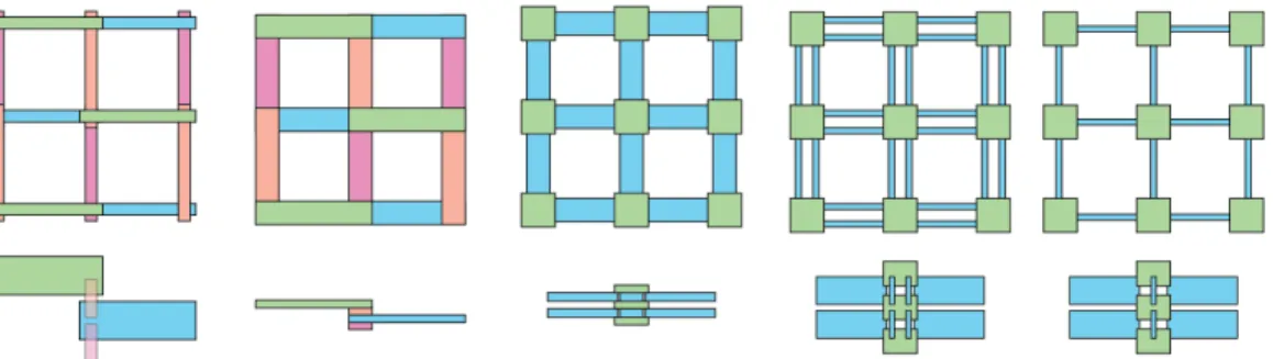
Based on these limitations, a further geometry was developed in order to better incorporate the mechanical and electrical functionality within the lattice. In my exploration of the design space of lattice-based discretely assembled structures, I restricted my search to regular rectangular lattices for their compatibility with press-fit construction methods and for their ease of laying out functionality in the cartesian axes (Figure 3-3).
Ultimately the new geometry relaxed the constraint of using a single part-type and introduced a secondary part-type, decomposing the lattice into edges and vertices, hereafter referred to as struts and nodes. In this decomposition, nodes are first assembled from four identical two-dimensional parts, connected through interlocking slots. Nodes are then connected to neighboring nodes through a pair of parallel struts (Figure 3-4).
This explicit decomposition into struts and nodes has a number of advantages. For one, it makes the parts more volumetric. Rather than two-dimensional panels, the parts are more cube-like, making them more amenable to automated assembly methods and allows them to be more easily manipulated. This volumetric nature also means that each slot is put under less torsional loading.
Figure 3-3: An exploration of the lattice design space. The leftmost design represents “Lego-GIK” construction while the second from the right represents the new geometry.
The rectangular nature of this lattice geometry allows these structures to tile the plane with a single layer and additional out-of-plane parts are not needed to give the layer its structure. The strut and node decomposition also provides a natural way to embed functionality in the lattice. As will be seen in the chapters to come, the struts often conveniently house functionality while the nodes provide connectivity.
Figure 3-4: The rectangular lattice is composed to node and strut part types. Four node sub-parts are assembled to form a single node. Nodes are then connected to neighboring nodes through parallel struts.
With just these two part-types (node and strut), this assembly framework is 2.5D. This means that three-dimensional structures can be made through the stacking of individual planar layers. While this enables the assembly of a wide range of capabilities, it only enables functionality to be arranged within the horizontal plane. With two additional part types, these structural planes can be joined orthogonally. This capability enables the construction of orthotropic planes that are then assembled into three dimensional objects with functionality in any desired orthogonal plane. An example of this is discussed in Chapter 8.2.
3.4
Sizing
It is possible to make these parts and structures at a wide range of different scales. I’ve chosen to focus on the development of millimeter-scale parts for a few reasons.
to use photolithographic processes to produce integrated machines as is done in MEMS but too small to use any off-the-shelf components. Currently most machines made at this scale are produced in monolithic processes to avoid the assembly step. Automating assembly at this scale could help open up the fabrication of integrated a machines with a more diverse range of functionality.
• It is still amenable to rapid prototyping. Laser micromachining, wire-EDM, and some machining processes are able to produce the required feature sizes at this scale to make inter-locking parts in a direct-write way.
Given this, I sized parts based on the minimum feature sizes of the fabrication tools available to me. In this case, that meant standardizing around 254 µm thick material and means the corre-sponding smallest feature size is also 254 µm. This enables relatively rapid production using the 150 µm wire on the wire-EDM.
The parts are sized to balance two objectives: (1) minimizing the pitch-spacing of the lattice (to maximize resolution) and (2) maximizing the functional area available to each part. The design space can be pictured by looking at two extremes. In prioritizing objective (1) one may seek to shrink the parts entirely until they are the minimum possible size to allow for the interlocking joints to function. On the other hand, prioritizing objective (2) would mean stretching the parts until the joint-interfaces become infinitesimally small compared to the body of the part.
Similarly, there’s a need to balance the size of the nodes and struts. Shrinking the nodes allows for the lengthening of struts (and therefore functional area) without affecting the pitch spacing of the lattice. However, doing this also necessarily shrinks the spacing between the pair of struts, reducing the overall strut volume. Ultimately the geometry that is used in this work strikes a balance between these but ensures that the struts are longer than they are wide, which is beneficial for a number of the functions that are developed and described in coming chapters.
3.5
Production
The parts that make this structure are two dimensional with relatively simple geometric features, allowing them to be easily fabricated using a range of different processes.
Figure 3-5: Node and strut parts are fabricated using wire-EDM, enabling the production of 108 parts in a single cut.
discharge machining) from 254 µm thick phosphor bronze. Arranging parts as a group (of six) and cutting a stack of (18) bronze sheets at the same time, enables the production of 108 parts with a single cut and takes just under one hour (Figure 3-5). These 108 parts are enough parts to assemble 27 nodes or 54 struts.
Nodes are assembled from four node parts manually using pliers. Automation of this assembly step is certainly possible and should be considered for scaling up the production rate of these parts.
Chapter 4
Mechanism
4.1
Compliant Mechanisms
In order to create machines, we need ways to constrain motion. Conventional machines at the macroscale often using bearings to constrain motion. Assembling bearings from individual discrete parts is hard to imagine unless the building block parts are significantly smaller than the bearing contact surfaces. In our case with millimeter-scale parts, this would entail building bearing surfaces from thousands or millions of parts.
Biology, however, demonstrates the potential for creating mechanisms and motion constraint without the use of bearings. While some biological bearings do exist [88], much of the movement that biology accomplishes is through the arrangement of rigid and compliant structures.
Compliant mechanisms is an emerging field of research that looks at recreating a wide variety of mechanisms and linkages using embedded flexural degrees of freedom rather than pins and bearings. These mechanisms offer advantages over conventional bearing-based degrees of freedom such as increased performance (high precision, low friction, low mass, reduced wear), lower cost (simplified fabrication, low part count), and ability to miniaturize [89].
Compliant mechanisms made using subtractive processes are normally limited to a single material and so their mechanism (force/displacement properties) is purely a function of geometry. Without the ability to spatially vary material properties such as stiffness and strength, these mechanisms often end up working only for a limited range of applications [89].
New methods in additive manufacturing have recently enabled the fabrication of compliant mech-anisms directly from digital designs with spatially varying material properties. These methods are still limited, however, in the range of material properties that are available. Additionally, the reso-lution of this technique limits the utility of mechanisms made this way at millimeter scales.
Instead, rather than printing or shaping material, the assembly approach I use enables the inte-gration of mechanism part types that exhibit a high degree of compliance about a certain axis while remaining stiff in other axes. These flexural parts can be produced using laminate based processes that enable the heterogeneous integration of materials giving the designer much more control over the resulting properties of the mechanism like stiffness and range of motion. Additionally, compared to multi-material additive technologies, the assembled mechanisms are able to take advantage of better material properties and much finer resolutions (e.g. thinner flexible regions) than are typical
Figure 4-1: Recent research on compliant mechanisms. Compliant mechanisms can be designed as lattice metamaterials [25] and have been shown to be capable of being used as an amplifying and inverting mechanism [90], auxetic materials [91], and robot appendages [92].
for additive manufacturing approaches.
This laminate based approach to manufacturing compliant mechanisms has been explored in-creasingly in recent research [93][94][27]. The technique is often referred to as PC-MEMS (Printed Circuit Micro-Electromechanical Systems) [8]. Mechanisms made using this approach can be con-structed to have a very high degree of compliance on-axis while remaining stiff off-axis [95].
4.2
Part Types
Two part types enable the assembly of a wide range of planar mechanisms (Figure 4-2): (1), a part with a single flexible degree of freedom and (2), a part with two flexible degrees of freedom. While it may not be possible to discretely assemble continuous rotary or linear constraints using discrete parts (at least at this scale and resolution), it is possible to assemble flexural mechanisms that approximate these motions, which exhibit a high degree of compliance within a certain axis or plane and high stiffness off-axis. Figure 4-2 shows common mechanism motifs that can be assembled from these two part types. In particular, two highlighted motifs are the simple rotary hinge and four bar linkage, which can be used to approximate linear motion.
4.3
Modeling
4.3.1
Kinematics
The discrete parts of this assembly framework provide a natural way of decomposing a complex linkage to evaluate its mobility. Parts assemble into a rectangular lattice framework in which pairs of nodes are connected by struts. This strut is what houses the mechanical degrees of freedom of the flexure hinges. Gruebler’s equation can be used to characterize the mobility of some common
Figure 4-2: Two part types (left) are necessary to enable a wide variety of planar mechanisms. A series of strut motifs are characterized based on the Gruebler mobility criterion. Two motifs that are commonly used are highlighted: a revolute joint (top) and a parallelogram four-bar linkage mechanism that can be used for linear motion constraint (bottom).
strut arrangements (Figure 4-2). Gruebler’s equation is defined as: DoF = 3(N − 1) − 2L − H
where N is the number of bodies or links (including the ground link), L is the number of lower order pairs (arresting two degrees of freedom), and H is the number of higher order pairs (arresting a single degree of freedom).
The constraint of linear motion rests on the ability of the parallelogram flexure to approximate linear motion over small displacements. The parallelogram mechanism is straightforward to model and simulate using simple rigid-body models. In this case, I find that the parasitic motion is related to two parameters: L (the distance between the flexure hinges) and d (the magnitude of linear displacement). The error motion is given simply by:
Error = e = L −pL2− D2
True straight-line linear motion constraints can be assembled with a few more parts. For example, by stacking two of the simple parallelogram linkages on top of one another, perfect straight-line motion constraint can be achieved. The caveat with this design, though, is that it is only well constrained for small displacements. With large displacements (> 15 deg), it reverts from a single degree-of-freedom mechanism to a two-degree of freedom mechanism. Other researches have explored modifications and additions to these mechanisms that help constrain them over larger displacements [96] [97].
These two part types are able to assemble any planar mechanism (given unbounded size). Even within confined machines, they span a wide range of desirable mechanisms and transmissions. For example, Figure 4-3 demonstrates the assembly of a transmission that converts linear motion into the rotational motion of a gripper. It also shows the assembly of a transmission that converts rotary motion into straight line motion for use as a jumping leg. Finally it demonstrates the assembly of a
Figure 4-3: A variety of transmissions assembled from the two flexural part types. A gripper must convert linear motion into rotary motion. A jumping leg converts rotary motion into straight-line motion. And a walking motor decouples and distributes two independent degrees of freedom to a motor tip.
transmission that decouples and distributes two independent actuated degrees of freedom to a single drive tip in the case of a walking motor.
4.3.2
Quantization of a continuous range of transmission ratios
Given that these two part types enable the assembly of a wide range of mechanism, the question naturally arises: Can these two part types assembly any planar (pin-jointed) mechanism? To which, the answer is yes, but only if given an unbounded envelope. However, with volumetric constraints the answer is harder to define and a better question becomes: How closely can this discrete set of parts approximate a continuous range of transmission ratios?
A simple lever-based linear to linear transmission serves as a good representative test case for this analysis. With unlimited space constraints, pin-joints placed on a lattice can approximate any transmission ratio with arbitrary precision. To achieve ratios very close to certain desired ones, however, will require a very large number of parts. To achieve the exact ratio of 2.45, for example, would require 49 + 20 = 69 parts (since the ratio is 49/20).
This is improved by introducing a sidedness to each hinge such that it is located on a lattice but is either shifted to the left or right by an amount, D. In these assemblies, in which a pair of strut-parts makes up a single strut, this is equivalent to picking which of the strut-parts has the hinge. This simple additional parameter drastically reduces the number of parts required to achieve a certain level of precision.

![Figure 1-3: The goal of enabling on-demand robot fabrication has been approached by ways includ- includ-ing: folding-based methods (A,B) [8] [24], soft robotics (C,D) [10] [25], and digital material (E,F) [26] [21].](https://thumb-eu.123doks.com/thumbv2/123doknet/14750920.580125/18.918.143.773.730.987/figure-enabling-fabrication-approached-folding-methods-robotics-material.webp)
![Figure 1-5: Biological machines exhibit modularity and reusability. The same motor proteins (A) [15] and microtubules (D) [51] that help organize the cell (B,C) [52] [53] are also used to actuate flagella mechanisms of swimming sperm (E) [13]](https://thumb-eu.123doks.com/thumbv2/123doknet/14750920.580125/22.918.140.783.561.772/biological-machines-modularity-reusability-proteins-microtubules-organize-mechanisms.webp)
![Figure 3-1: Recent research on lattice structures. Additive manufacturing has improved to enable the direct printing of complex lattices [76] (A)](https://thumb-eu.123doks.com/thumbv2/123doknet/14750920.580125/33.918.138.786.649.846/figure-research-structures-additive-manufacturing-improved-printing-lattices.webp)