EcoGRAFI
2nd International Conference on Bio-based Building Materials & 1st Conference on ECOlogical valorisation of GRAnular and FIbrous materials June 21th - 23th 2017
Clermont-Ferrand, France
AN ASSESSMENT OF THE THERMAL STORAGE CAPACITY OF HEMP-LIME
USING THE TRANSIENT PERFORMANCE RATIO METHOD
Aidan Reilly, Oliver Kinnane Queens University Belfast, Ireland
o.kinnane@qub.ac.uk
Abstract
Many claims are made regarding the superior thermal performance of high heat capacity materials under the general heading of thermal mass. However, the benefits of thermal mass are poorly quantified in existing literature. These issues often become more important in the case of biobased materials, where thick, monolithic wall construction leads to a stronger connection between a building's structure and the indoor environment. New materials include hemp-lime concrete, which offers a combination of structural, thermal and hygroscopic properties that make it suitable for incorporation into the building envelope. Hemp-lime has long been proposed to offer excellent thermal mass performance, yet this impact is poorly quantified in existing literature. This paper uses the Transient Energy Ratio (TER) method, developed by these authors, to compare the performance of hemp-lime concrete walls with traditional solid wall and cavity wall constructions.
Keywords:
Transient energy ratio; TER; thermal mass; diffusivity; hemp-lime
1 INTRODUCTION
High thermal mass is often cited as a beneficial aspect of bio-based construction materials. However, many of the concepts surrounding these benefits are poorly quantified in the literature. This applies both to the benefits of increased thermal mass, and the performance of bio-based buildings. Both national construction guidelines, and academic literature, often offer little beyond platitudes and statements that are simply inaccurate. Examples include “A massive building uses less energy than a similar low mass building due to the reduced heat transfer through the massive elements” [Portland Cement Association 2017]), and “there is no upper limit for the amount of well-designed thermal mass” [Autodesk 2017]. More rigorous research shows, however, that thermal mass can have drawbacks as well as benefits [Reilly 2016, Reilly 2017, Tsilingiris 2006].
These problems are particularly acute as regards hemp-lime concrete; as a comparatively new bio-based construction material, many claims are made, despite the fact that it remains somewhat poorly characterised. For example, its thermal conductivity is often stated to be lower than measured values actually show (such as a claim by the Building Research Establishment in the UK of a thermal conductivity: “0.07–0.09 Wm-1K-1 giving
a typical U-value at 300 mm of 0.21 Wm-2K-1”, when
conductivity values reported in the literature more commonly exceed 0.1 Wm-1K-1) [Walker 2014].
The benefits of thermal mass intuitively seem most applicable to regions with high diurnal temperature variation, and sites with high solar flux and cool nights
would seem to have the most to gain. Indeed, most case studies in the literature have been in exactly these sorts of climates, such as the Mediterranean region and hot arid or semi-arid climate zones. There is a widespread assumption that these results will be applicable in a qualitative sense to other climates, even if the exact results are not; but this is not the case. Indeed, recent work has shown that in heating dominated climates such as northern Europe, high thermal mass can lead to an increase in energy use rather than a decrease [Karlsson 2013]. Work conducted in parallel with the work presented here, using the same techniques, has shown that these conditions are not uncommon, and actually likely dominate in many regions. Consequently, in colder areas, the assumption that high thermal mass leads to energy savings is very often incorrect. Use of the transient energy ratio and transient performance ratio allows for rapid assessment of a given site, use case and construction typology: the method is more generalised than detailed building simulation and can be used by architects and engineers much earlier in the design process, before decisions on building layout and construction method have been taken; and therefore, decisions regarding appropriate construction methods can make use of this information at an earlier stage of the design process.
The generalisable nature of the technique also allows researchers to analyse wall typologies without the limitation of studying only specific case study buildings. This is the approach taken in this paper: the transient energy ratio technique is first summarised, and then
used to assess a range of bio-based materials in terms of their dynamic thermal performance.
2 THE TRANSIENT ENERGY RATIO METHOD 2.1 Method Summary
The transient energy ratio was demonstrated by Reilly and Kinnane [Reilly 2017]. In summary, the method involves the following:
• Calculate the U-value for the wall section in question (termed U)
• Simulate the thermal behaviour of the wall, using boundary conditions representative of the climate and indoor occupancy pattern of interest
• Use the actual energy flow through the wall in the dynamic simulation to calculate an effective U-value (termed Ue)
• Divide Ue by U to find the transient energy ratio (TER) The most time-consuming part of the method, is the dynamic simulation, and the calculation of the effective U-values; this is necessary to capture the true behaviour of the walls. As walls have heat capacity, their thermal response during fluctuating conditions is not described by the U-value alone. In conditions of changing surface temperatures, heat may be stored and returned to the indoor and outdoor environment: this is the basis of thermal mass. A dynamic simulation attempts to capture these effects by modelling the response of a wall to varying temperatures. The effective U-value is the quantity which, when used with the mean temperatures, gives the actual energy flow through the wall.
This actual energy flow may be greater or less than that predicted based on the static U-value, and this ratio is termed the TER. If the TER is less than one, the thermal mass of the wall offers energy savings, over and above any savings purely due to a low conductivity. In this case, higher thermal mass walls could offer greater benefits, and increasing the thermal mass should be considered. On the other hand, if the TER is greater than one, the wall is leading to greater energy use than predicted by a static analysis: in this case, the thermal mass is a drawback, and design changes should seek to minimise the thermal mass of the wall instead of maximising it. For a TER in the region of one, thermal mass has little influence, and in such a case other considerations (such as a low conductivity) will likely dominate. Greater detail of this method can be found in Reilly and Kinnane, 2017. 2.2 Static Analysis
The static analysis was simply an evaluation of each wall’s U value, calculated in the standard manner as in Eq. 1 below (where L is the thickness of each material,
k is the conductivity, and the subscript indicates the
material). 1 𝑈= 𝐿1 𝑘1+ 𝐿2 𝑘2+ ⋯ + 𝐿𝑛 𝑘𝑛 (1) 2.3 Dynamic Analysis
The principle of the TER method is to use a dynamic simulation of a wall section. To comply with the method, any simulation method that accurately predicts internal wall temperatures may be used, with a 1D numerical simulation generally the easiest. For this work, a finite element (FE) model was created using commercial FE software (Abaqus 6.12). The walls were modelled using heat transfer elements with a
typical mesh dimension of around 1 mm, and the increment time in the model was set such that in no step did the temperature change exceed 0.1 K. Heat transfer at the wall surfaces was modelled according to ISO 6946, as in Eq. 2 below. (where 𝑣̅ is the mean wind speed, 𝜖 the emissivity, 𝜎0 the Stefan-Boltzman constant and 𝑇0 the relevant environmental temperature)
ℎ = 4 + 4𝑣̅ + 4𝜖𝜎0𝑇03 (2) The external temperature was applied as a heat source/sink, connected to the outer surface of the wall via Eqn. 2. The internal temperature was either specified in the same manner (during periods of active heating/cooling), or allowed to float freely in response to heat exchange with the wall’s internal surface. Solar flux was applied to the relevant surface as a power input per unit area. The details of the active heating/cooling system were not considered; while a more efficient system would obviously reduce the primary energy use, this study was concerned only with the heating/cooling energy demand.
The output from the model, was an energy transfer per unit area (J/m2). This was measured on the interior
surface of the wall, and gave an average heat flux for the time period in question (W/m2). This average heat
flux per unit area was divided by the mean temperature difference to give the effective U-value. In this way, the effective U-value accurately reflects the heat loss/gain through the wall, but has units of W/m2/K, making it
directly comparable with the standard U-value calculated through a static analysis.
3 WALL TYPOLOGIES AND CLIMATES
CONSIDERED 3.1 Wall Typologies
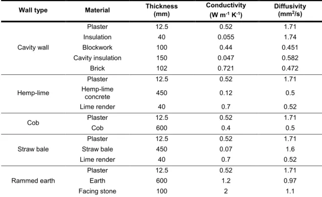
Four bio-based wall materials are considered in this paper: hemp-lime concrete, straw bales, cob, and rammed earth. These were compared with a masonry cavity wall construction. The material properties and wall descriptions are given in Table 1. Providing general values is complicated by the wide range of thermal properties for many of the materials considered; it is not possible to give a definite value for the thermal conductivity of stone, for example, as there is so much natural variation. However, the values chosen are indicative mid-range values, and the general approach taken here could easily be adapted to model the specific differences between, for example, sandstone and granite walls. This study looks at broader classes of wall type, and more detailed analysis is left for further work.
3.2 Climate
For this study, outdoor weather data was used from Belfast, Northern Ireland. Belfast, in common with most of the UK and Ireland, has a wet maritime climate, with comparatively mild winters and summers and is characterised by high precipitation. A representative week of weather data was chosen for the dynamic analysis: a week in January 2016, with weather data obtained from UK Met Office. Temperatures ranged from 275 to 288 K. Temperatures, wind speeds and solar flux were all typical for the time of year.
Virtually all domestic construction in the UK and Ireland employs some form of mechanical heating system for several months of the year, and in this respect Belfast is entirely typical.
Tab. 1: Wall typologies and material properties
Many of these values are subject to considerable variation; the specific heat capacity of straw bales, in particular, seems poorly characterised in existing literature, and those for earth and stone vary substantially (a factor of two or more) depending on the exact source. These values are based on a review work by Clarke (1990), with the exception of the values for cob (Goodhew 2000).
4 RESULTS 4.1 Heat capacity
The heat capacity of traditional wall types is often assumed to be dramatically higher than modern construction. However, there are very many exceptions to this rule, particularly when the ‘modern construction’ used is a masonry cavity wall meeting contemporize standards. Table 2 gives values of the heat capacity per unit wall area for the walls considered here, and it can be seen that a masonry cavity wall construction falls about midway between the natural materials, with straw and hemp substantially lower and cob and rammed earth much higher. Of course, these values depend on the wall thickness, which will vary from case to case; but it would be very difficult to build a wall of rammed earth with equivalent heat capacity to the masonry wall presented here – it would be less than 300 mm thick in total – while a straw bale wall of equivalent heat capacity would be impractically thick (around 5 m).
While the heat capacity of a wall gives an indication of its dynamic performance, in an inhomogeneous wall the ordering of the layers is also important, and different walls with the same heat capacity can perform differently – hence the importance of the TER.
4.2 Static performance
The static performance of the walls in determined by the thickness and thermal conductivity of each layer, measured by the standard U-value. These are presented in Table 2. In this regard, the hemp-lime wall is the closest match to the cavity wall, with straw being rather better and cob being worse. For a permanently occupied building in static outdoor conditions, the heat loss (or gain) would be determined entirely by U.
Rammed earth stands out as being particularly poorly performing, with a static U-value more than ten times that for the straw bale wall. Conductivity values for rammed earth vary dramatically, with quoted values in the literature ranging (at least) from 0.4 to 2.1, primarily depending on moisture content. However, even at the lower end of this range, the U-value will be much higher than that for a straw bale wall; and many claims are made for rammed earth structures on the basis of its high thermal mass enhancing their performance. Consequently, a comparison between the straw bale and rammed earth walls provides a very good study of the influence of thermal mass.
4.3 Dynamic Performance and Transient Energy Ratio
The dynamic performance of these walls was assessed by carrying out a one-week finite element simulation, as described in Sections 2 and 3. For the analysis in Belfast, it was assumed that the occupants would heat the building between 6 and 8 am, and 6 and 10 pm. The building was unheated outside these hours.
The dynamic response is very different from the steady-state analysis, as Figure 1 shows. Due to the heat capacity of the wall, the indoor temperature only falls to around 288 K during the unoccupied times (when the heating is off), despite an outdoor temperature that falls below 280 K. The heat capacity of the wall leads to both an energy saving and an energy penalty, and these two effects counteract each other: a wall with a high heat capacity, takes more energy to heat up, but then stores its heat for longer, meaning the temperature at the start of the next heating period is higher. Which of these two effects dominates determines whether thermal mass is beneficial or detrimental in a particular scenario.
Wall type Material Thickness
(mm) Conductivity (W m-1 K-1) Diffusivity (mm2/s) Plaster 12.5 0.52 1.71 Insulation 40 0.055 1.74
Cavity wall Blockwork 100 0.44 0.451
Cavity insulation 150 0.047 0.582 Brick 102 0.721 0.472 Plaster 12.5 0.52 1.71 Hemp-lime Hemp-lime concrete 450 0.12 0.5 Lime render 40 0.7 0.52 Cob Plaster 12.5 0.52 1.71 Cob 600 0.4 0.5 Plaster 12.5 0.52 1.71
Straw bale Straw bale 450 0.07 1.6
Lime render 40 0.7 0.52
Plaster 12.5 0.52 1.71
Rammed earth Earth 600 1.2 0.97
Tab. 2: U-value, Heat Capacity, Effective U-value and Transient Energy Ratio
Fig. 1: Temperatures of the cavity wall indoor and outdoor surface for three days in Belfast
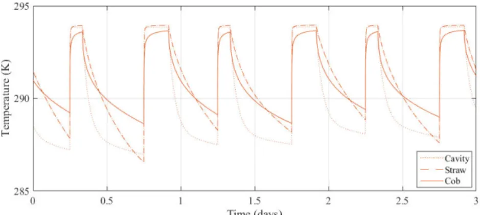
Figure 2 shows the indoor temperatures for the cavity, straw and cob walls (with medium, low and high heat capacities, respectively). It is clear that the cob wall takes longer both to heat up and to cool down; by contrast, the straw wall heats and cools much more rapidly. Its low heat capacity means that the wall responds more quickly both to undesired (externally-induced) and desired (mechanically-(externally-induced) changes. In addition to predicting temperatures, the model also predicts heat fluxes through the walls. Dividing the total heat flux over the course of the week by the mean temperature difference, gives the effective U-value Ue. Ue for each wall is given in Table 2, along with the transient energy ratio, which is found as in Equation 3 below.
TER =𝑈𝑒
𝑈 (3)
The TER for all these scenarios lies between 2 and 3. This indicates that the drawback of greater heat input at the start of each heating period, more than outweighs the benefits of heat retention from one heating period to the next. In these cases, thermal mass is detrimental, and substantially so: a theoretical wall with no heat capacity (but the same conductivity) would use less than half the energy for heating than these walls do.
As the TERs for all the walls lie in the range 2 to 3, they can be discussed as a group in terms of their dynamic performance. For a cold climate requiring constant indoor heating, such as that of Belfast, thermal mass is a significant drawback. The effect of heating up the structure at the start of each heating period takes a substantial amount of energy, and only a small fraction of this energy is returned to the occupied space at a later time, with most being lost to
the outside environment. For a typical domestic use case, between half and two thirds of the heating energy used will be lost in heating up the building structure – this is what is indicated by the TER values, where a TER of 1 would indicate energy consumption exactly equal to a prediction based on the U-value alone.
Results showing a TER greater than 1, suggest that reducing the heat capacity of the wall (for an equivalent insulating capacity) will lead to better thermal performance. To test this, a new, thinner straw bale wall was modelled, with the thickness of the straw layer reduced to 100 mm. The U-value for this wall matched that for the original cob wall (0.66), thereby allowing a direct comparison between a low and high thermal mass wall with the same mean conductivity. Ue for the thin straw wall was 0.74: this wall used less than half the energy that the cob wall did, despite the two walls having the same U-value.
5 DISCUSSION
Cob and rammed earth are examples of vernacular construction techniques that have recently received more attention due to their perceived environmental benefits, not least benefits associated with high thermal mass structures. Straw bale and hemp-lime construction are newer developments, which also appear to offer reduced environmental impact as compared to conventional contemporary construction using concrete and masonry. While all these materials do indeed offer many benefits, the claims associated with reduced heating and cooling loads in high thermal mass buildings need to be examined much more carefully. Wall Overall thickness (mm) U-value (W m-2 K-1) Heat capacity (kJ/m2/K) Effective U-value (W m-2 K-1) Transient Energy Ratio Cavity 404.5 0.23 271 0.60 2.57 Hemp-lime 502.5 0.26 166 0.68 2.59 Cob 612.5 0.66 484 1.83 2.79 Straw bale 502.5 0.15 77 0.34 2.19 Rammed earth 712.5 1.67 928 4.49 2.58
Fig. 2: Comparison of indoor surface temperatures in three wall types with light, heavy and intermediate heat capacity (straw, cob and cavity respectively)
In a heating-dominated climate such as that of northern Europe, high thermal mass is likely to be associated with increased energy consumption rather than decreased consumption. While it is often claimed that poor insulation values associated with some construction types can be offset by virtue of high thermal mass, this is demonstrably not the case, and indeed the reverse is often true: high thermal mass construction leads to worse performance than predicted based solely on insulation values.
This is shown by the result given here for the thin straw wall compared to the cob wall: for the same U-value, the thin straw bale wall takes less than half as much energy for heating as the cob wall. indeed, of the representative walls in this study, only the (thick) straw wall (with Ue = 0.34) comes close to achieving the performance assumed in most national codes, which typically specify U-values in the region of 0.2.
Given that high thermal mass will often not lead to the purported energy savings in cold climates, are the wall types considered here appropriate? It remains true that the embodied energy of the cavity wall is likely to be much higher than the others considered here; but the embodied energy for most buildings is very much smaller than the use energy. This is particularly the case for long-lasting buildings such as houses. In order to minimise the lifetime energy use, the embodied energy should be equal to the use energy. In most cases, this would result in an impractically thick wall; consequently, in order to minimise overall energy use the objective will often become one of using the lowest conductivity materials available, almost regardless of embodied energy.
Of course, there are many other factors involved in choosing construction materials besides energy consumption, which may tilt the balance in favour of one or another material. But bearing in mind the high conductivity of earth and stone, monolithic walls made from these materials do not seem to be appropriate choices in cold climates where building energy use is dominated by heating. Hemp-lime walls, on the other hand, have a thermal performance similar to that of good masonry cavity wall construction; and in this case, other factors such as the lack of thermal bridges, lower embodied energy, hygroscopic nature, etc., may make it a better choice. The addition of an extra insulating layer, while using hemp for the structural component, may improve the performance further. However, straw bale construction seems to outperform both masonry and other biobased materials without the
need for extra insulation. Its poor loadbearing capabilities likely render it unusable for highrise buildings, but where it can be used it seems to offer superior thermal performance. Its low heat capacity is a distinct advantage in cold climates, where high heat capacity materials result in wasted energy use in many cases.
The TER analysis of these scenarios captures the dynamic behaviour of a range of wall types. The analysis method is applicable to any wall typology, building use case and climate; but the specific results given here must be used cautiously if applied outside the cases considered. There will be cases where the assumptions are incorrect; for example, in the case of a cold climate where substantial solar energy is available outside occupied hours, the capacity to store heat may be beneficial. But in general, it is unlikely that any advantages of thermal mass can be sufficient to offset poor insulation values, and except in very specific cases, thermal mass is a drawback rather than an advantage in cold regions.
6 CONCLUSIONS
In cold climates, high thermal mass cannot be relied on to counteract poor thermal insulating performance. In heating dominated climates high thermal mass is much more likely to be a hindrance than a boon, and other things being equal minimising heat capacity would be a better objective than maximising it. Certain biobased materials, in particular straw, have a combination of low thermal mass and low conductivity; simulations show that these will perform well. Hemp-lime also seems to offer comparable thermal performance to masonry cavity walls, and may offer other advantages. Solid earth and stone structures, without insulation, tend to have higher U-values than masonry cavity walls, and the downsides attached to this cannot be remedied by the high thermal mass associated with these materials.
7 ACKNOWLEDGEMENTS
The authors would like to thank the European Union for funding this project under the auspices of the Horizon 2020 programme. This work was undertaken as part of the Impress project under grant number R6525ARC.
8 REFERENCES
[Autodesk 2017] Autodesk Sustainability Workshop, https://sustainabilityworkshop.autodesk.com/buildings/t hermal-mass, accessed on 15 May 2017
[Clarke 1990] Clarke, J.A.; Yaneske, P.P. & Pinney, A.A.; The Harmonisation of Thermal Properties of Building Materials. Technical Report, Building Research Establishment
[Goodhew 2000] Goodhew, S.M.R. The Thermal Properties of Cob Buildings of Devon. PhD Thesis, University of Plymouth
[Karlsson 2013] Karlsson, J.; Wadsö, L. & Öberg, M. A conceptual model that simulates the influence of thermal inertia in building structures Energy and Buildings, 2013, 60, 146 - 151
[Portland Cement Association 2017],
http://www.concretethinker.com/solutions/Thermal-Mass.aspx, accessed on 15 May 2017
[Reilly 2016] Reilly, A.; Kinnane, O.; A parameter for quantifying the transient response of walls to dynamic thermal loading Advanced Building Skins, Bern, Switzerland, 2016
[Reilly, 2017] Reilly, A.; Kinnane, O.; The Impact of Thermal Mass on Building Energy Consumption. Submitted to Applied Energy.
[Tsilingiris 2006] Tsilingiris, P.; Wall heat loss from intermittently conditioned spaces—The dynamic influence of structural and operational parameters Energy and Buildings, 2006, 38, 1022 - 1031
[Walker 2014] Walker, R; Paiva, S.; Moisture transfer and thermal properties of hemp–lime concretes Constr. Build. Mater., 2014, 64, 270-276