HAL Id: hal-02519297
https://hal.archives-ouvertes.fr/hal-02519297
Submitted on 26 Mar 2020
HAL is a multi-disciplinary open access
archive for the deposit and dissemination of
sci-entific research documents, whether they are
pub-lished or not. The documents may come from
teaching and research institutions in France or
abroad, or from public or private research centers.
L’archive ouverte pluridisciplinaire HAL, est
destinée au dépôt et à la diffusion de documents
scientifiques de niveau recherche, publiés ou non,
émanant des établissements d’enseignement et de
recherche français ou étrangers, des laboratoires
publics ou privés.
Adrien Pelat, François Gautier, Stephen Conlon, Fabio Semperlotti. The acoustic black hole: A
review of theory and applications. Journal of Sound and Vibration, Elsevier, 2020, Recent Advances
in Acoustic Black Hole Research, pp.115316. �10.1016/j.jsv.2020.115316�. �hal-02519297�
Contents lists available atScienceDirect
Journal of Sound and Vibration
j o u r n a l h o m e p a g e : w w w . e l s e v i e r . c o m / l o c a t e / j s v i
Special Issue: Recent Advances in Acoustic Black Hole Research
The acoustic black hole: A review of theory and applications
Adrien Pelat
a,∗, François Gautier
a, Stephen C. Conlon
b, Fabio Semperlotti
caLaboratoire d’Acoustique de L’Université du Mans (UMR CNRS 6613), Av. O. Messaien, 72085, Le Mans cedex 9, France bApplied Research Laboratory, The Pennsylvania State University, State College, PA, 16804, USA
cRay W. Herrick Laboratories, School of Mechanical Engineering, Purdue University, West Lafayette, IN, 47907, USA
a r t i c l e i n f o Article history: Received 1 April 2019 Revised 6 March 2020 Accepted 9 March 2020 Available online XXX Handling Editor: Li Cheng Keywords:
wave trapping
vibration control and mitigation inhomogeneous structures lightweight structures metastructures structural waveguides
a b s t r a c t
The Acoustic Black Hole (ABH) is a technique for passive vibration control that was recently developed within the Structural Dynamics and Vibroacoustics communities. From a general perspective, the ABH effect is achieved by embedding a local inhomogeneity in a thin-walled structure, typically a beam or a plate. This inhomogeneity is characterized by a variation of the geometric properties (although material variations are also possible) according to a spa-tial power law profile. The combination of a local stiffness reduction, due to the power law variation of the wall thickness, and of a local increase in damping, provided by the concur-rent application of viscoelastic layers, gives rise to a significant reduction of the wave speed and to a remarkable enhancement of the attenuation properties. As an elastic wave travels within an ABH, its speed experiences a smooth and continuous decrease. In the ideal case, that is when the wall thickness vanishes at the ABH center, the wave speed decreases to zero. In the non-ideal case, that is when the ABH has a non-zero residual thickness at its center, the wave speed still decreases smoothly but it never vanishes. In this latter case, which is of great importance for practical applications, the ABH is typically combined with lossy media (e.g. vis-coelastic layers) in order to achieve significantly enhanced structural loss factors. If the speed of an incoming wave can vanish inside the ABH, it follows that this object behaves as a wave trap that extracts elastic energy from the host medium without, in principle, ever releasing it. Several characteristic properties are generally observed in structures with embedded ABHs: significant reduction in vibration and acoustic radiation levels, low reflection coefficient at the ABH location, localized vibration and trapped modes, and existence of cut-on frequencies. Contrarily to passive vibration methods based on viscoelastic materials, the ABH was devel-oped and applied to reduce vibrations and structure-radiated noise without increasing the total mass of the system. More recently, applications to other areas including elastic metas-tructures, energy harvesting, vibro-impact systems, and cochlear systems were also investi-gated. This review is intended to provide a comprehensive summary of the state-of-the-art of ABH technology, spanning from theoretical and numerical contributions to practical applica-tions.
© 2020 The Authors. Published by Elsevier Ltd. This is an open access article under the CC BY-NC-ND license (http://creativecommons.org/licenses/by-nc-nd/4.0/).
∗
Corresponding author.
E-mail address:Adrien.Pelat@univ-lemans.fr(A. Pelat).
https://doi.org/10.1016/j.jsv.2020.115316
0022-460X/© 2020 The Authors. Published by Elsevier Ltd. This is an open access article under the CC BY-NC-ND license (http://creativecommons.org/licenses/ by-nc-nd/4.0/).
Since its initial formulation, about four decades ago, the concept of the ABH has attracted growing interest within the engi-neering community. The basic operating principle exploited in an ABH finds its roots in the properties of retarding structures as described in the seminal work of Mironov [3]. He studied the behavior of flexural waves traveling in a beam terminated by a wedge having a power-law decreasing thickness profile. By using an analytical approach, Mironov showed the possibility of achieving a non-reflecting or, equivalently, a fully absorbing termination. Assuming an ideal design of the tapered wedge (that is the thickness vanishes at the tip of the wedge), the velocity of the incoming flexural wave can be reduced to zero so that the wave never reaches the tip of the wedge and hence it is never reflected back. If the wedge is not coupled with any dissipative mechanism (e.g. viscoelastic material), the flexural wave is trapped inside the wedge and, given that the total mechanical energy must be conserved, the particle displacement grows unbounded and the tip of the wedge becomes a point of singularity. How-ever, most of the wave can be absorbed if the wedge is coupled with energy dissipation mechanisms. In both cases, the flexural wave enters the wedge and it is never reflected back into the original structure, hence giving rise to a zero reflection coefficient. About a decade later, the concept of a retarding structure was extended by Krylov [4] to two-dimensional configurations by embedding axisymmetric circular pits with power-law varying thickness into plates. As with the retarding wedges, the circular tapered pit was able to slow down and trap flexural waves, hence serving as an omni-directional wave absorber. In the ideal case, and in the absence of dissipative mechanisms, the center of the ABH is associated with a singularity of the particle displacement which goes to infinity. The analogy of these properties with those of an optical black hole led Krylov to coin the term “acoustic black hole”.
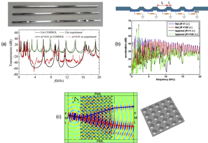
The physical concept of such a wave trapping has been developed in the context of structural dynamics. Strictly speaking, the denomination of “Vibration Acoustic Black Hole” would be more appropriate. This denomination would also help differentiating the application of this concept to acoustic ducts with variable area terminations. Despite these somewhat purely semantic differences, the term ABH is currently commonly used and accepted by the community to refer to power-law type absorbing terminations or indentations. Some examples of typical geometries employed to achieve ABH structures are shown inFig. 1, including typical 1D ABH made with wedge-shaped beam (a), a spiral ABH [1](b), an acoustic waveguide with varying wall impedance made with branch discs of increasing diameters [2] (c), a 2D ABH made with an axisymmetric pit (d), or slots (e,f). In (a) and (b) ABHs are located on the edge of the host structure while in (d), (e), and (f) they are embedded in the host structure.
1.2. Birth and growth of the ABH research field: a short historical perspective [5–7]
Following the initial study from Mironov, the ABH field has seen a steady growth which has rapidly accelerated during the last decade.Fig. 2(a) shows the number of either peer-reviewed journal articles or conference proceedings per year since 1988. Particularly striking is the marked increase in the number of publications over the last five years [8] which witnesses the
Fig. 1. Examples of, so-called, retarding structures based on the concept of power-law taper: (a) tapered wedge, (b) Spiral ABH (from Ref. [1]), (c) Acoustic tube with axially varying impedance made with a collection of branch discs of increasing diameters (from Refs. [2]), (d) two-dimensional circular acoustic black hole, (e) one-sided, and (f) two-sided ABH slots.
Fig. 2. Summary of the available literature related to the Acoustic Black Hole effect: (a) histogram of the journal and conference papers published since 1988 (updated from
Ref. [8]), (b) classification and numbering of the published journal articles according to the sections of this review article.
growing interest of the engineering community in this topic and its applications. To date, the exhaustive list of ABH related publications includes 101 peer-reviewed papers.Fig. 2(b) proposes a classification, which reflects also the general outline of the present review paper. In general, this paper focuses on the work presented in journal publications hence, other than for a few exceptions, conference proceedings will not be discussed in this review. In the historical development of the ABH concept, several phases can be distinguished. These phases approximately correspond to the main ideas at the basis of the ABH effect whose applications can be summarized as follows:
∙The original idea consisted in using a retarding structure to build a zero-reflection termination. Mironov proposed this idea initially for flexural waves in a tapered beam [3] and later extended it to an acoustic tube with an axially varying wall impedance [9]. Such implementations mostly concerned the ideal ABH effect with no dissipation. The effect was purely reactive.
∙A first important extension of the original idea consisted in adopting an absorbing layer to contrast and, possibly, to eliminate the wave reflection associated with the non-vanishing thickness (hence the non-zero wave speed) at the end of the ABH termination. The idea of exploiting an absorbing layer in conjunction with the ABH effect was introduced by V. Krylov in 2004 [10] and experimentally demonstrated in 2007 [11].
∙Another significant step in the development of the ABH effect concerned the extension of the absorbing wedge concept to 2D configurations. More specifically, a pit of power law profile was explored as a way to integrate the absorbing effect inside the plate surface. In this latter case, we refer to an embedded ABH or an ABH indentation. Later on, several studies have highlighted some features of this tapered scatterer, namely wave focusing, low reflectivity, enhanced local damping and energy harvesting.
sections. Section2presents the basic principles and the main elements for the physical understanding of the ABH effect when inserted at the end of a beam. Section3describes the features of 2D ABHs when embedded into panels, in terms of structural dynamics and vibro-acoustics. Sections2 and 3are largely based on the modelling strategies that have been developed specif-ically for the physical analysis of ABHs. Section4is dedicated to experimental methodologies that were developed to evaluate the performance of ABH structures. Section5reviews the different types of applications of the ABH concept and shows practical examples of the theoretical, numerical, and experimental techniques presented in previous paragraphs. Some conclusions are finally presented in section6.
2. Physical interpretation of the ABH effect in wedge-shaped structures
In its general one dimensional form, an Acoustic Black Hole is realized in a beam-like structure by imposing spatial varia-tions of the thickness and damping properties. Such a system is a complex inhomogeneous structural waveguide which can be represented by several kinds of models of increasing complexity.
2.1. ABH principle
2.1.1. Ideal zero-reflection wedges [3,12,13]
The phase and group velocities of flexural waves in a beam decrease with the decreasing thickness. Thus, if the thickness varies smoothly and reaches a zero value, the corresponding wave velocities also reduce to zero. It follows that the wave can never reach the tip of the wedge, hence it cannot be reflected. This concept of a retarding structure, originally proposed by M. Mironov [3], was implemented in a tapered beam of power law profile whose thickness variation is given by h(x) =
𝜖
xm, where m is a real constant defining the power-law profile, x is the axial coordinate along the wedge,𝜀
is a constant (Fig. 3(a)). The case of a quadratic wedge was studied by V. Krylov [12]. This class of profiles was chosen in order to satisfy a condition of sufficient smoothness, that is the variation of the flexural wave number must be small over a distance comparable to the wavelength. In the framework of the Euler-Bernoulli assumptions and in the harmonic regime (implicit time factor ej𝜔tis supposed,𝜔
beingthe circular frequency), the equation of motion is written as −
𝜌
L(x)𝜔
2w(x) +𝜕
2
𝜕
x2D(x)𝜕
2w(x)𝜕
x2 =0,
(1)where w(x)is the beam flexural displacement,
𝜌
L(x)the linear mass density, D(x) = E(x)h(x)3∕12(1−𝜈
2)the bending stiffness,h(x)the thickness, E(x)the Young’s modulus,
𝜈
the Poisson’s ratio. The Wentzel, Kramers, and Brillouin (WKB) method can be used to provide analytical solutions of the differential equation(1)with different orders of approximation [13]. The first-order WKB approximation, called the geometrical acoustics approximation, provides the variation of the local phase velocity c𝜙(x),c𝜙(x) = ( E
𝜔
2 12𝜌
(1−𝜈
2) )1∕4√ h(x),
(2)and the local group velocity cgr(x) = 2c𝜙(x), as well as a varying amplitude term A(x)of a propagating wave (seeFig. 3, xABH being the abscissa marking the start of the ABH)
A(x) =A(xABH)
( h(xABH)
h(x) )3∕4
.
(3)It is observed that the phase velocity tends to zero if the thickness h(x)tends to zero. As a consequence, it is shown that if m
>
2, the travel time of a wave packet from a starting location in the uniform region to the wedge tip tends to infinity as the wave approaches the tip of the wedge. The incident wave amplitude also tends to infinity. Such an ideal wedge does not produce any reflection, therefore the wave appears to be fully absorbed. From an energy conservation perspective, this mechanism gives rise to a process of energy accumulation inside the taper where both the strain energy density and the particle displacement tend to infinity at the tip of the wedge. Under these conditions, the tip of the wedge becomes a point of singularity. Note that in practical structures, it is not possible to fabricate a wedge having residual thickness equal to zero. Even realizing finite but very thin wedges poses significant complexities due to the deformation produced by the mechanical and thermal loads associated with the manufacturing case. An easy way to circumvent this difficulty is to modify slightly the profile by setting h(x) =𝜀
(x+x1)m.Fig. 3. (a) practical ABH termination in a beam where the power-law profile is truncated and coated with a thin viscoelastic layer. (b) comparison of the modulus of the
reflection coefficient of an ABH termination predicted by the geometrical acoustics model without (full line, from Ref. [3]) and with (dashed dotted line, from Ref. [10]) added damping layer, and by the plane wave model (dashed line, from Ref. [14]). Significant decrease of the reflection coefficient is obtained from the ABH effect without increasing the mass of the system.
It is important to highlight that the residual thickness h1=
𝜀
xm1 discriminates between an ideal and a realistic implementation
of the zero-reflection wedge and that both profiles are not equivalent. The residual thickness has a detrimental influence on the absorption performance of the wedge because it drastically increases the coefficient of reflection. As an example, in metallic structures, a residual thickness equal to 0.1% of the thickness of the uniform part can generate a reflection of about 70% of the incoming wave [3]. Note that the ABH profile includes a sharp edge between the wedge and the uniform beam, at x = xABH, which could also cause back scattering. In practice, simulations show that this effect is weak and can be ignored.
2.1.2. Practical ABH wedges with absorbing layer [10,15]
Considering the limitations of the ideal ABH, V. Krylov [10,15] explored the effect of absorbing layers applied to tapered wedges in order to reduce the effects produced by the finite residual thickness. The thickness of the added layer is considered thin with respect to the plate thickness so that the Ross-Ungar-Kerwin model [16], used to describe sandwich structures, can be simplified to provide the following equivalent material loss factor
𝜂
(x) =𝜂
p+3hlEl h(x)Ep
𝜂
l,
(4) where Epand
𝜂
p are the elastic Young’s modulus and the loss factor of the plate, respectively. El and𝜂
l are the elastic Young’s modulus and the loss factor for the viscoelastic layer. Under these conditions, the reflection coefficient can be ana-lytically derived from the WKB approach by integrating the complex wave number k(x)R=exp ( −2 ∫ x x0 Im(k(x))dx )
.
(5)The main effect of the viscoelastic layer is that of drastically reducing the reflection coefficient even in presence of a truncated profile. Eq.(4)is valid only when the layer is much thinner than the plate which, of course, is an assumption that is not valid everywhere along the wedge, particularly near the tip of the wedge where the thickness of the plate is also very small [15]. As an example,Fig. 3(b) shows the variations of R computed from Eq.(5)for an aluminium beam with m=2, a minimum thickness ht=10
𝜇
m (corresponding to a typical thickness obtained with CNC machining), a profile given by𝜖
=0.35, xi=0.0653 m, xt=0.0053 m. Both cases with and without damping layer are considered; the damping layer has the following characteristics: El=7 GPa,𝜌
l=1000 kg m−3,𝜂
l=0.4, hl=0.1 mm. The reflection coefficient in this case reaches 0.5 at 4 kHz. It is also noted
that geometrical acoustics leads to monotone variations of R with frequency. Even if the use of exact models (presented in the next section) highlight more complicated variations of R, its estimation from the geometrical acoustics theory captures its main trend and it is useful for an early stage design of an ABH termination.
2.2. Analysis of the ABH effect based on linear models of increasing complexity 2.2.1. Reflection coefficient via the plane wave approximation [14,17,18]
Evanescent waves are ignored in the geometrical acoustics approach. Exact solutions allowing estimation of the wave field inside the medium, modeled as an inhomogeneous structural waveguide, can be obtained using several methodologies like the transfer matrix method or the scattering matrix method [19,20], and the Rayleigh-Ritz method [18]. On the other hand, the impedance matrix method is known as the most robust and efficient way to solve exactly waveguide problems without experiencing numerical instabilities. The impedance matrix method has been widely studied and applied to acoustic waveguides [21] and, later, adapted to structural waveguides under plane wave approximation [14]. The key idea is to turn a Boundary Value
Fig. 4. (a) dispersion curves of the ABH: wavenumbers ki(full line: real part; dashed line: imag. part) associated to the waves i=[1–4] as function of the wavenumber k0
defined in the uniform area, LABH =xABH−x0is the ABH length for dimensionless representation (from Refs. [23]); (b) parametric study of the cut-on frequency defined
by Eq.(6)for an ABH placed in a thin aluminium structure.
Problem (BVP) into an Initial Value Problem (IVP). The governing equations are rewritten as a Riccati equation, verified by the local impedance matrix. Starting from the initial value at the tip, the Riccati equation is numerically integrated using a Magnus scheme, yielding the frequency- and spatially-dependent impedance matrix of the beam. Based on the impedance matrix, either the reflection matrix of the extremity or the scattering matrix of any segment can be obtained.
Typical results for the reflection coefficient of an ABH beam termination obtained via the impedance matrix method are compared to those from geometrical acoustics inFig. 3(b). The exact solution is characterised by a typical oscillatory trend of the reflection coefficient versus frequency. These oscillations occur around the monotonic decreasing solution provided by geometrical acoustics. Each sudden decrease in amplitude corresponds to the resonance of a trapped mode localized in the ABH profile [22]. These modes are complex valued and are discussed in section2.2.5based on more detailed numerical models.
The exact solution of the Euler-Bernoulli equation for an ABH having arbitrary power-law profile h(x) =
𝜖
xmcan be obtained in the case of conservative ABHs (i.e. with no added damping) [17]. For m = 2, the Euler-Bernoulli equation is a Cauchy-Euler equation, and the exact solution without damping is given by a linear combination of four monomials. For m>
2, the Euler-Bernoulli equation was transformed into the generalized hypergeometric differential equation via changes of variables, and the exact solution was derived in linearly independent and regular form without singularities. Such analytical solutions provide reference solutions for wedge-shaped beams without damping and under plane wave approximation.2.2.2. Cut-on frequency of the ABH effect
All experimental characterizations of ABH structures (see section4) show that no wave absorption is achieved below a cut-on frequency, which is defined as the frequency below which the wavelength of the incoming wave is much larger than the characteristic length of the ABH (typically the length of the wedge or the diameter of the axisymmetric taper). In practice, the knowledge of this cut-on frequency is of particular important during the design of ABH devices in order to achieve wave absorption in the desired frequency range.
It is possible to determine the cut-on frequency from the analysis of the wave dispersion inside the ABH. Initially, this analysis was performed for a 2D circular ABH of quadratic profile seen as a penetrable scatterer [23]. However, by reducing the problem to only the circumferential order n = 0 (i.e. the case of an incoming cylindrical wave to a circular scatterer), the model is equivalent to the 1D case. In this latter scenario, the analysis of the wave dispersion is reported inFig. 4(a). Two evanescent waves are found: convergent in (a.1), divergent in (a.2), based on the sign of very small real part. More interestingly, k3in (a.3) and k4in (a.4) exhibit a cut-on wavenumber below which the two associated waves are evanescent (similarly, the two
waves become propagating at wavenumbers above the cut-on value). In particular, k4corresponds to a convergent exponentially amplified wave which typically represents the ABH effect. The analytical expression of the corresponding cut-on frequency is found to be fcut−on= h0 2
𝜋
L2ABH √ E0[40−24𝜈
] 12𝜌
(1−𝜈
2),
(6)where h0 is the uniform thickness outside the ABH, LABH = xABH − x0is the ABH length (seeFig. 3(a)), E0is the Young’s modulus,
𝜌
is the density,𝜈
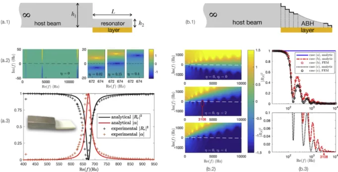
is the Poisson’s ratio. Eq.(6)is valid for m = 2. Remarkably, the expression shows that in a structure with a given uniform thickness and material, the cut-on frequency only depends on the length of the full ideal ABH length LABH = xt − x0and not on the truncation radius.Fig. 4gives a representation in the form of a cut-on frequency chart for ranges of beam thicknesses and TNA length usually encountered.Fig. 5. Analysis of the critical coupling conditions for a beam termination made with (a) a uniform beam of small thickness h1compared to the thickness h2of the host beam
(from Refs. [24]), and (b) an ABH termination (from Refs. [25]). The analysis is presented using(1)a schematic drawing,(2)a representation of log10(|R|)in the complex
frequency plane,(3)the value of|R|for real values of the frequency.
2.2.3. Interpretation of the ABH damping effect from the critical coupling conditions [24,25]
The decrease of‖R‖can be analyzed using the concept of critical coupling, applied to a so-called open resonator. The approach can be introduced and illustrated by considering the case of an elementary resonator (Fig. 5(a1)) consisting of a thin beam of uniform thickness h2placed at the end of a host beam of greater thickness h1[24]. The modes localized in this ele-mentary termination are similar to those of a clamped/free beam. The reflection conditions of a bending wave on this locally resonant termination are examined through the reflection coefficient that can be calculated for complex values of the frequency, allowing performing an analysis in the complex plane. In this plane, the reflection coefficient gives rise to zeros, associated with conditions of perfect absorption, and poles corresponding to the resonance frequencies of the termination. When the system is conservative, these poles and zeros are found in pairs, symmetrical with respect to the axis of the real frequencies (Fig. 5(a2),
𝜂
l = 0). On the real axis,‖R‖ = 1. The introduction of losses via damping layers breaks the symmetry of the pole/zero pair andtend to bring the zeros closer to the real axis (Fig. 5(a2),
𝜂
l = 0.
02). Thus,‖R‖becomes less than 1 for real frequencies near the complex zero. Tuning the losses allows placing the zero exactly on the real axis (Fig. 5(a2),𝜂
l = 0.
15). In this case, theinter-nal losses of the resonator equal the energy leakage by radiation into the host beam. This situation corresponds to the critical coupling conditions that induce a perfect impedance adaptation between the support beam and the resonator. These conditions result in unit absorption or zero reflection for an incident wave as shown inFig. 5(a.3). Note that, when losses increase fur-ther, the zero required for critical coupling crosses the real axis and these conditions are lost. This may seem counter-intuitive because the increase in losses leads to a reduction in absorption but underlines a fundamental point in the design of this type of absorber: the need for a balance between dissipative mechanisms internal to the termination and those induced by its radiation. This analysis can be applied to the case of an ABH beam termination approximated by a piece-wise constant thickness profile (see Ref. [25] andFig. 5(b1)). In the conservative case, where both the losses of the beam (
𝜂
= 0) and of the layer (𝜂
l = 0) are ignored, the complex frequency plane exhibits a large number of modes trapped in the ABH (Fig. 5(b2)). The increase in layer losses𝜂
lbrings all the zeros back to the real axis. For example, for𝜂
l = 2 only the 5th mode is critically coupled to f = 3108 Hz and all other modes are close to the real axis. A significant overlap of zeros is also highlighted, resulting in a very low reflection of the ABH termination over a wide frequency range (Fig. 5(b.3)). Finally, the very good damping performance of ABHs can be explained by the spectrum of their complex modes: an ABH is by nature an excellent critical coupling element of local resonances. The critical coupling conditions provide the conditions for optimum damping design.2.2.4. Interpretation of the ABH trapping effect from the multimodal approach [26,27]
In the terminal area of a 1D ABH where the thickness is the lowest (seeFig. 1-a), the wavelength may become no longer large compared to the beam width [28]. The resulting wave field is then two-dimensional and 2D models are more adequate to describe these plate-like motions.
The multimodal approach is well adapted to study the ABH beam seen as a 2D inhomogeneous structural waveguide. On one hand, when considering the hypotheses of slowly varying properties [26], this approach provides a more reliable model in the high frequency range, compared to 1D models. On the other hand, 2D models can be used to extend the 1D impedance
Fig. 6. (a) view of an ABH thickness profile where the different colors represent the areas in which the modes q=3 (orange), q=5 (blue), q=7 (pink) are evanescent at the selected frequency f=1000 Hz; (b) modulus of reflection coefficients‖Rq‖associated with the modes q=1,3,5,7 along the ABH termination at f=1000 Hz (from Ref.
[27]). (For interpretation of the references to color in this figure legend, the reader is referred to the Web version of this article.)
Fig. 7. (a) poles𝛼kof a finite beam without (circles) and with (dots) an ABH termination and examples of associated modal shapes; (b) modal overlap factor of the ABH
beam compared to the reference, obtained from numerical simulations and experiments (from Refs. [28]).
matrix method regardless of the specific taper coefficient of the ABH profile [28]. Each quantity of the system state vector (displacement, slope, moment, and force) is developed on the basis of the transverse modes defined over the beam width. Each mode is associated with a set of forward and backward waves, either propagating or evanescent. The reflection coefficient‖Rq‖
associated to a transverse mode q can then be calculated.
Fig. 6shows a numerical study of‖Rq‖for the first transverse modes numbered by q = 1
,
3,
5,
7 propagating along the ABH profile and without considering the reflection at the free edge. Each propagating mode q is associated with a reflection coefficient‖Rq‖that, at a given frequency, depends on the abscissa where it is calculated.Fig. 6(b) shows an abscissa xq, called a cut-on abscissa, which separates the zone ]0, xq] where R<
1 and the zone [xc,∞[ in which R=1. The abscissa xqdepends on the frequency (f=1000 Hz is considered in 6). A careful study of the dispersion relations for each mode q [28] shows that it is associated with evanescent waves in [xq,
∞[, while it is associated with propagating waves in ]0,xq]. These zones are depictedusing different colors inFig. 6(a). Therefore, it is possible to minimize the reflection coefficient of the plane mode by transferring part of its energy by modal coupling to the other upper modes locally trapped in the ABH. For example, this can be done by adding a defect (point weight added) to the end of the black hole. In this case, it is shown in Refs. [27] that a 10% reduction in the reflection coefficient can be obtained.
2.2.5. Free and forced responses of ABH beams of finite length from finite difference and finite elements methods [1,28–33]
The dynamic behavior of ABH thin structures of finite length can be studied using a Kirchoff plate numerical model based on the finite difference method [28]. The model is able to describe any arbitrary variations of the mechanical properties along the ABH taper, as well as the possible 2D wave field effects in the beam width, as discussed in the previous section2.2.4. The problem is reduced to a homogeneous linear system whose inversion provides the set of the eigenvalues
𝛼
kof the system, defined as𝛼
k= −j𝜔
k√ 1−
𝜉
2k−
𝜔
k𝜉
kwith𝜔
kthe eigen-pulsation and𝜉
kthe modal damping ratio.Fig. 7(a) shows a typicalIn the case of a reference beam having uniform thickness and losses, all modes are distributed according to a line so that they are all associated with the same modal damping ratio
𝜉
k =𝜂
∕2, where𝜂
is the loss factor of the beam (Fig. 7(a), green circles). First, the ABH termination produces a global damping effect. Most of the eigenvalues are organized in the complex plane along a line whose angle with the imaginary axis can be interpreted as a homogeneous equivalent loss angle in the beam (Fig. 7(a), green points). Results show that this loss angle is multiplied by a factor of%10 with respect to the loss angle of the reference beam. Second, a local damping effect is also recognizable by the appearance of isolated eigenvalues characterised by a particularly large modal damping factor. These so-called “hyper-damped” modes (modes 23 and 41, for example) differ from the previous modes (mode 42, for example) based on their modal shapes that are either i) oscillatory over the beam width or ii) very localized in the ABH.The consequence of these two effects can be analyzed using the Modal Overlap Factor MOF, which is an indicator of the smooth or resonant feature of the mobility transfer function, defined as the ratio between the frequency bandwidth at the half amplitude of a resonance peak and the average modal spacing. It is shown that MOF = d
𝜂
f, where d is the modal density. This indicator is very well suited to define low (MOF<
30%), mid (30%<
MOF<
100%) and high frequency (MOF>
100%) ranges.Fig. 7(b) compares the numerical and experimental MOFs obtained for ABH and reference beams. Results show a large increase in the MOF that can reach the typical values of the mid frequency range, which is inherently more damped. This effect is directly related to the increase in modal damping ratio discussed above, as the modal density is only slightly modified by the insertion of the ABH [28]. The MOF increase occurs only above the ABH cut-on frequency, discussed in section2.2.2.
In a more general way, Finite Element (FE) simulations using 3D elastic elements have also been performed to investigate the effects on the reflection coefficient of tapers with exponent larger than m = 2 [30]. In particular, the variations of the “normalized wavenumber” [29] along the taper appears to be directly linked to the performances. Similar types of FE simulations were applied to parametric variations [32] and multi-objective optimization [31].
Spiral ABHs, whose baseline is rolled into an Archimedean spiral configuration, were introduced as an alternative to the straight ABH when the available space to apply an ABH termination is limited. Both 3D FE simulations [1] and experimental characterizations [33] showed encouraging damping performance even at low frequencies due to the increased length of the taper.
2.2.6. Wavelet decomposition and fractional order models [34–39]
By expanding the transverse displacement field of the beam over the basis of a set of Mexican hat wavelets, the equation of motion can be turned to a set of linear equations, which is solved to simulate both the free and the forced structural responses. This semi-analytical model has been well validated in the case a classical Euler-Bernoulli ABH beams with a rectangular cross-section [34], with a circular cross section [38], and in the case of a sandwich beam with an aluminum core and steel upper/lower layers [37]. The wavelet decomposition model was also adapted to the case of plate embedding 2D ABH strips indentations under the general Rayleigh-Ritz framework by using Debauchies wavelets scaling functions. This modeling technique appears to be able to overcome major technical difficulties in modeling ABH structures, particularly to address the typical drastic wavelength fluctuation induced by the power-law profile [34]. It is also useful to demonstrate and predict the loss of the ABH effect in a beam of finite size [35]: this phenomenon occurs at specific frequencies which correspond to local resonances between the structure boundaries and the excitation point.
A very recent approach to the simulation of the ABH effect relies on the use of fractional order integro-differential operators [39]. This approach, currently limited to 1D structures, exploits the unique properties of these operators in order to recast the wave equation, describing the wave field within the ABH area, by using fractional order spatial derivatives. While the original wave equation in an inhomogeneous medium is of the second order in space and it is characterized by spatially varying coeffi-cients, the fractional formulation results in a governing equation with fractional order and constant coefficients. Although this approach is still at a very early stage, the most immediate advantage is the ability to capture the ABH absorbing effect without the need to model its intrinsic three-dimensional nature. This aspect is particularly important for the simulation of either large structures or systems with a large number of ABHs due to the significant computational burden involved.
2.3. Nonlinear effects in ABH wedges [40–42]
The main weakness of linear ABH devices is their ineffectiveness at low frequency. It is possible to design an ABH which exploits geometric non-linearities to transfer energy from low to high frequencies, where the ABH is effective [40,41] (see section3.2). In addition, material nonlinear effects can also become significant when high amplitude motion interacts with material micro-inhomogeneities [42]. Both phenomena can lead to additional wave absorption.
In classical ABH designs, a balance between large displacements and high dissipation near the tip maintains the system dynamics in a linear regime. However, when considering sufficiently long ABH, geometrical non-linearities may appear and induce energy transfer from low to high frequencies. This energy transfer results in an enhancement of the damping properties below the ABH cut-on frequency [40]. The response of such beam harmonically excited with an increasing driving force shows a progressive spectral enrichment and a transition to a turbulent regime characterized by a broadband spectrum (Fig. 8(a2)). Numerical analyses based on a Von Kàrmàn plate model of variable thickness [40] show that an optimal topology consists of an ABH profile connected to an extension in the form of a constant-thickness beam (see the extension inFig. 8(a.1)). The gain produced by non-linearities strongly depends on the damping layer, which on one side is essential for the ABH effect but on
Fig. 8. (a) measured spectrogram (dB scale) of the response of a beam with 35 cm long ABH harmonically excited at 102 Hz with a force ramp [0–15]N over a period of 40s
(from Ref. [40]); (b) simulated time response of a vibro-impact ABH beam (from Ref. [41]). For both non-linear ABH, energy transfer from low to high frequency is achieved with a resulting enhancement of the ABH efficiency.
the other reduces the effect of the linearities. The ideal configuration includes coating only the ABH profile so that non-linearities can develop in the extension.
Even if geometric non-linearities have shown some success in enhancing the ABH performance by means of targeted energy transfer [40], the overall gain is still limited. Another opportunity to achieve broadband performance comes from vibro-impact designs as shown inFig. 8(b1)in which contact non-linearities induce very fast energy transfers [41]. As a result, the energy decay time can be drastically reduced (Fig. 8(b)). When such beam is excited by a noise in the band [0–500]Hz, the energy at low-frequency is redistributed almost instantaneously over the whole spectrum at each impact and it is quickly attenuated by the ABH effect (Fig. 8(b.2)). Numerical analysis of the system highlights the central role of contact stiffness, which must be high to cause energetic impacts. In the most favorable cases, a reduction of about 10 dB is observed on resonances below the ABH cut-on frequency.
On the other hand, the quadratic hysteretic nonlinearity characteristic of micro-inhomogeneous materials is known to cause softening of the material and diminishing the wave speed. In this case, the elastic modulus becomes strain-dependent. When considering the propagation of flexural waves in a host structure with an embedded ABH, the asymptotic theory [42] shows significant differences between the power law and the linear profiles when the structure operates in the non-linear regime. This difference is, of course, in addition to those produced by the different taper profile. For ABH profiles, the higher the effect of the non-linearity, the slower the decay of the bending wave approaching the edge of the wedge. However, non-linear effects cannot cause complete absorption of the bending wave in the ABH, hence indicating the need to also properly combine the effect of linear absorption.
2.4. ABH effect in acoustic ducts [2,9,43]
The ABH effect can also be achieved in acoustic waveguides in order to achieve, for example, anechoic terminations or muf-flers. The reduction of the speed of sound of a pressure wave propagating in an acoustic tube can be achieved using an spatially varying wall impedance [9]. Practically, this varying impedance can be achieved by placing in a section of the duct a set of rings whose inner radii decrease to zero according to a power law variation (Fig. 1(c)). The result is a retarding effect similar to that observed in beams and plates with embedded ABHs. If the number of ring-cavities is large enough (so that the spacing is small compared to the wavelength), the wave propagation inside the waveguide can be treated as a continuous problem. In that case, the transfer matrix method can provide good results approaching the solution of the continuous problem [43]. This approach can then be used to analyse the influence of the design parameters (e.g. number of rings, ring thickness, ring minimum inner radius, damping) for both linear and quadratic ABHs [2]. Such a retarding effect is also known as “slow sound” and can be obtained by using an array of side branch tubes of increasing lengths [44,45].
Fig. 9. (a) scheme of a typical 2D circular ABH with a central plateau; (b) snapshots at different times showing the focusing effect for an incoming wavefield (the ABH limits
are denoted by a dotted line). The colormap represents experimental results and red lines denote numerically calculated ray trajectories; (c) ray trajectories in the cases of (c.1) an ideal ABH with zero thickness at the center, (c.2) an imperfect ABH with residual thickness h1 =1 mm, (c.3) ABH with central plateau of thickness h1 =0.2 mm
and (c.4) h1=1 mm (right). The thickness in the uniform plate is h=5 mm (from Ref. [47]). (For interpretation of the references to color in this figure legend, the reader
is referred to the Web version of this article.)
3. Analysis of circular ABH indentations embedded in thin plates
For many practical applications, manufacturing an ABH at the edge of the structure is not a viable option (e.g. due to the required boundary conditions). The natural 2D extension of the 1D ABH consists in an axisymmetric indentation with a radial power-law profile embedded in a thin-walled structure (e.g. thin plate). After Krylov proposed such layout [4], Georgiev et al. [14] set up a first experimental demonstration of a 2D ABH. Since then, various geometrical layouts have been proposed. As an example, 2D ABH with either a central hole, or a central plateau, or a central added mass. Several modeling strategies have been developed to treat this class of problems and they are briefly reviewed in this section.
3.1. Lensing and focusing features [46–50]
Considering 2D circular ABHs, focusing and lensing effects are due to the radial decrease in celerity. Following numerical studies [46], the lensing and focusing effects were shown experimentally [48] by using a laser line source to excite Lamb waves in a plate with embedded 2D circular ABH. Following early works from Mironov and Krylov on 1D ABH, the effect of 2D circular ABHs on the propagation of flexural waves in the high frequency regime was studied using geometrical acoustic theory [49,50]. Both cases of an ABH with and without a central hole were considered. In the case of a central hole, the conversion of incoming Lamb waves into either a standing wave within the pit or an edge-localized wave were observed.
The analysis of the focusing effect can be performed based on the usual 2D equation of motion for a thin inhomogeneous plate under geometrical acoustics assumptions [47]. A ray trajectory equation in a medium with a gradient index is then derived:
d
ds(n(x
,
y)s) = ∇n(x,
y) (7)where s is the ray coordinate defined along the ray trajectory, ds a differential element on the trajectory from a given point of coordinates(x
,
y), and n(x,
y) =√h0∕h(x,
y)the local index of refraction with h0the uniform thickness outside the ABH. Thisequation is analogous to the optical ray equation and describes the ray trajectories only as a function of the local index, that is independently of the frequency.
Eq.(7)can be solved numerically by considering a Taylor expansion truncated to the second order term and by providing proper initial conditions on the vector s. Typical results obtained from this approach in the case of a 2D circular ABH with a central plateau (Fig. 9(a)) are reported inFig. 9(b). Due to the thickness profile, the rays are strongly deflected from their initial straight trajectory once they enter the ABH. Experiments confirmed that the wavelength decreases as the thickness decreases, that is as the wave approaches the ABH center. Both results show the focusing effect taking place not exactly at the ABH center.
Fig. 9(c) shows the influence of the geometric parameters on the focusing capabilities of ABH indentations. In the ideal case (i.e. vanishing thickness at the ABH center, seeFig. 9(c1)), it is shown that there exists a critical trajectory that discriminates rays that converge to the center and those that diverge. The critical trajectory depends on the power of the profile: the higher the power m, the higher the critical angle. The total focusing is reached with m = 3. In the practical case of ABH with non-zero
Fig. 10. (a) schematic of a circular plate with an ABH in the center and of the corresponding experimental setup (from Ref. [52]); (b) experimental and simulated mobility from the “composite loss factor model” (from Ref. [52]); (c) Plot of the scattering cross-section as a function of the dimensionless wavenumber of a circular ABH (blue line) compared to the one of a simple hole (gray line) (from Ref. [23]); (d) 3 examples of measured ABH trapped modes (from Ref. [56]); (d) unwrap phase of the cross mobility of an ABH plate compared to the reverberant and the propagating theoretical cases in order to identify the cut-on frequency (from Ref. [53]). (For interpretation of the references to color in this figure legend, the reader is referred to the Web version of this article.)
residual thickness at the center (Fig. 9(c2)), focusing leads to a confined high intensity area that is shifted area from the ABH center and that results from ray concentration. The partial focusing is enhanced when using larger m and smaller h1. In the case
of ABH with a central plateau (Fig. 9(c3 and c4), only a portion of the rays converges to the plateau. The percentage of focused energy only depends on the plateau thickness h1while the rays curvature still depends on the profile power m.
3.2. Damping, scattering, and resonant features [23,51–55]
In the case of a circular plate with an embedded ABH in the center, as shown inFig. 10(a), an analytical solution of the equation of motion of a radially variable thickness plate can be found when the pit power-law profile is m = 2 [51]. After a change of variables, the problem can be reformulated in the form of root extraction of a polynomial, which can be accomplished analytically. The losses are represented by a uniform equivalent loss factor, which is clearly an oversimplification since a radial loss factor gradient is essential for the ABH effect [28]. Despite such simplification, the numerical simulation of the plate driving mobilities exhibit a general trend in good agreement with experimental data.
To represent more realistically the losses, a numerical approach consists in approximating the circular ABH by a sequence of annular slices [52]. Each slice has constant thickness and is associated with a constant composite loss factor, so that the radial gradient of the loss factor is approximated. Results show good agreement with the mobility experimental data (Fig. 10(b)). The model also shows that the modal loss factors of the ABH plate are significantly greater than the loss factors of a simply coated plate, which is consistent with similar results obtained for 1D ABH [28]. Such damping features are also well observed by the Rayleigh–Ritz method in other types of ABH indentations, called power-law profiled grooves [54].
To study more in depth the scattering properties of a second order power-law circular indentation with central hole and without coating layer, the model in Ref. [51] is generalized to a circumferential order greater than n = 0 [23]. Notably, the scattering cross-section that corresponds to the integration of the scattered far field shows strong perturbations compared to the case of a simple hole (Fig. 10(c)): the peak values are associated to the resonances of modes trapped within the ABH (Fig. 10(d)). The study of the scattering features has been generalized to any arbitrary power-law profile of circular ABH using hypergeometric governing equations [55], similarly to Ref. [17].
When a plate of finite size is highly damped, the contributions of all resonances are greatly reduced and the finite structure behaves almost as an infinite structure. On the contrary, in a very weakly damped finite plate, the resonances are very pro-nounced and lead to a highly reverberant field. The case of ABH plates can be analyzed in relation to these two extreme cases by studying the phase variations of cross-mobility[53], defined as the ratio between the velocity at one observation point and the force applied at the excitation force in the frequency domain. The phase variation is a specific signature of the structure and highlights two opposite behaviors. At low frequency, modes are resonant and the measured phase follows the phase given by an “idealized reverberant plate” model. At high frequencies, the ABH effectively dissipate energy and the measured phase is
similar to the phase of the infinite plate. Finally, the frequency at which the sudden change in behavior appears provides another definition of the cut-on frequency.
3.3. Fluid-structure interaction features 3.3.1. Acoustic radiation in free field [56–63]
Vibration reduction is the main feature of the ABH effect. The consequence of this reduction on the acoustic radiation into the domain surrounding the plate is discussed in several experimental and numerical studies.
In the case of a multi-indentation rectangular plate, an experimental analysis conducted according to ISO 3744 [57] demon-strates that the cumulative damping added by each indentation provides a substantial reduction in both the flexural vibrations and the radiated sound power. This result occurs in spite of the high vibration amplitudes at the center of the ABHs. Such obser-vation is confirmed by parametric analyses performed via Finite Element simulations [56] that provide the panel response, the localized modes, the modal loss factors, and the surface-averaged mobilities. Vibration reduction is observed. The sound power radiated by an ABH panel in free field conditions is measured according to ISO 9614-3 (consisting in time and space averaged radiated sound intensity measurements through a surface) by a moving intensity probe. It is shown that panels with periodic 2D ABHs exhibit 5–20 dB reduction in the radiated sound power, resulting from the high mechanical damping added by the ABH effect, and from the reduction in radiation efficiency due to the reduction in the wave speeds within the ABHs. An initial analysis of these two mechanisms is proposed in Ref. [58] using both finite element and boundary element analyses. The relative importance of both mechanisms depends on the ABH diameter, on the presence of internal holes in the centers of the ABHs, and on a characteristic frequency for which the free plate bending wavelength is equal to the ABH diameter. According to Ref. [23], such characteristic frequency is another possible definition of the cut-on frequency.
A sound radiation model for a 1D ABH is proposed in Ref. [59]. Considering an infinitely baffled tapered beam, the Transfer Matrix method, combined with a spatial wavenumber transform allows the computation of the modal radiation efficiency. For a uniform beam, the modal radiation efficiency reaches a maximum close to the critical frequency, defined as the frequency for which the wavelengths in the structure and the fluid coincide. A beam mode is called a critical mode if its resonance frequency is close to the frequency for which the modal radiation efficiency reaches its maximum. If its resonance frequency is lower than this maximum, the mode is called subsonic and it is not radiating. If its resonance frequency is larger than the maximum, it is called supersonic and it does radiate. The total radiation efficiency of a beam is maximum around the first critical mode. For an ABH profile, due to the ABH wave speed reduction, the first critical mode is shifted to an order and higher frequency than that of the host medium beam. The direct consequence is the reduction of the total radiation efficiency of the ABH beam. The ABH effect transforms supersonic bending waves into subsonic ones, leading to acoustic radiation efficiency reduction.
Further, the radiation efficiency of a 2D circular ABH embedded in an infinite plate can be studied using a wavelet expansion combined with the Rayleigh integral [60]. The ABH cut-on frequency and the critical frequency of the host plate, separating the subsonic and the supersonic frequency ranges, are the two key-parameters explaining the variation of the radiation efficiency. The radiation efficiency for the ABH panel is reduced due to structural-acoustic decoupling resulting from the reduction of wave speeds inside the ABH regions. In the case of structures that may have band gaps, such as with ABH tunneled, sound radiation reduction can also be achieved in the low frequency range below the characteristic frequency [63].
ABH wedges without visco-elastic coating were used to maximize sound radiation in the ultrasonic range [61]. It is expected that, in the absence of damping, the sound radiation is increased due to the large vibration amplitude localized in the wedge. In the ultrasonic range, ABHs have also been used in an Acoustic Emission (AE) setup [62]. Acoustic emission is a phenomenon of elastic wave generation due to mechanisms of relaxation of residual stresses within the material that induces local micro-motions. In a finite size structure, the reflected AE wave at the edges increases error and prevents accurate analysis. The use of ABH wedges at the edges helps increasing the Signal to Noise Ratio (SNR), hence facilitating the analysis of the direct AE component.
3.3.2. Noise reduction inside cavities [64–66]
ABHs have been proposed to reduce the noise inside cavities bounded by elastic panels with multiple two-dimensional (2-D) ABH indentations. The indentations lead to significant noise reduction inside the cavity. This is a direct consequence of the vibration reduction of the plate on which the ABH is embedded, and a reduction in the coupling strength between the plate and the cavity. The spatial coupling coefficients, that capture the degree of morphological matching between structural modes and acoustic modes over interface, were found to play an important role in determining the overall noise reduction.
ABHs indentations are also shown to be good candidates to increase the TL of panels: TL measurements on panels with multiple indentations [64] show that they simultaneously increase TL and decrease mass, compared to a uniform plate. At coincidence, the damped ABH plate increases the TL by 6–9 dB despite having less mass than the uniform plate. This effect is interpreted by the authors as a structural acoustic decoupling due to the ABH effect. It is shown that most of the benefit was gained near and above the coincidence dip of the TL curve, while the response below coincidence generally followed mass law behavior.
same type of comparison is performed on tapered indentations (pits) of power-law profile, where the centers of the indentations were covered by a small amount of absorbing material (seeFig. 12(b)). Configurations without and with a small central hole produced a rather low reduction in resonant peak amplitudes. This result was attributed to the small effective absorption area. The ABH effect could be increased by extending the size of the central hole in the pit. When multiple indentations are used, the resulting damping increases substantially due to the cumulative damping performance of each pit. In Ref. [68], the reduction of the resonant peaks of the mobility was demonstrated for slots of power-law profile. Such ABH slots had the advantage of locating the ABH within the plate, as opposed to on the plate outer edges, while providing damping that is comparable to the outer wedges of power-law profile.
4.1.2. Full field measurement [69–71]
The absorption induced by the ABH effect results from the interaction of the incident waves with the ABH, which can be seen as a complex scatterer combining both local thickness and damping heterogeneities. At steady state, operational deflection shapes obtained using scanning laser vibrometry display locally trapped field of high amplitude within the scatterer (Fig. 10(d)). This is clearly due to the presence of localized modes within the indentation. During the transient regime, full field measure-ments are required to well capture the wave interaction with the indentations. Full field measuremeasure-ments with high space-time resolution can be achieved by combining optical digital holography and high speed cameras. The principle of high-speed holo-graphic metrology, its limitations, and its application to the investigation of traveling elastic waves propagating in beams and plates are presented in Ref. [69,70]. The interaction of an incident flexural wave with a 2D ABH is shown inFig. 13. A short video sequence, extracted fromFig. 17in Ref. [69] and reported in this manuscript inFig. 13, reveals the main features of the wave field interacting with the ABH. More specifically, the deviation of the wave fronts due to the scattering associated with the ABH, the local decrease of the wavelength, the local increase of the field amplitude, and the effect of the local damping.
Thermal full field measurements can also reveal ABH damping properties. The local dissipative mechanism leads to a tem-perature increase, which can be captured using a highly sensitive infra-red camera. To the best of our knowledge, such mea-surements were provided for the first time in Ref. [71]. For the 1D ABH configuration described in Refs. [71], the order the local temperature increase is found to be 500 mK in a region close to the ABH extremity, where the strain is maximum.
4.2. Post-processing for the identification of ABH features 4.2.1. Reflection coefficient [22,72,73]
The effectiveness of the acoustic black hole effect can be demonstrated experimentally by observing the decrease in ampli-tude of the resonance peaks and the smoothing of measured transfer functions (mobilities), which ultimately reveal a signif-icant increase in modal damping. The quantitative evaluation of the efficiency of a black hole termination can be performed using reflection coefficient measurements. In the case of ABH beam terminations, a Kundt-like measurement method has been used [72]. The measurement was made in the far field in order to evaluate the reflection coefficient associated only with the propagating waves. In the case of the free end, the reflection coefficient is R = −j. Results for several ABH extremities showed a clear decrease of the modulus of the reflection coefficient R. The phase of R due to the decreasing thickness profile was also investigated and interpreted by defining a correction length for the tapered termination. Results highlighted that the decrease was not monotone and that local modes of the termination were responsible for local reduction in the reflection coefficient [22]. These local reductions were also connected to the critical coupling mechanism [24].
As an alternative to frequency-domain approaches, time-domain experimental techniques have also been proposed. These techniques are effective in investigating the wave propagation and attenuation in a one-dimensional ABH plate [73] because the separation of the incident and reflected waves enables the extraction of the reflection coefficient. The reduction in phase velocity, the progressive attenuation, and the low reflection of the incident wave can be analyzed in space/time diagrams. Such analysis is experimentally viable in the high frequency range where wave separation can be achieved by accounting for the length of the incident wave front and the characteristic size of the system.
4.2.2. Wavenumber analysis [74,75]
Wave number analysis refers to different post-processing techniques of experimental data able to identify the dynamic and vibro-acoustic features of a vibrating structure. In the case of a 1D exponentially tapered rod, a methodology based on five
Fig. 11. (a) aluminum plate with an array of embedded ABHs; (b) wavenumber spectrum of an undamped ABH plate at 2500 Hz one third octave band with infinite plate
wavenumbers for uniform plate thickness (inner circle) and minimum ABH thickness (outer circle). The vibration energy is spread out over different wavenumbers due to the ABH effect and it is effectively bounded by the wavenumber of the minimum ABH thickness; (c) radiation efficiency of uniform, undamped, and damped ABH plates. Embedding ABH tapers increases the critical frequency of the plate. At 2 kHz the radiation efficiency of the damped ABH plate is 6 dB less than the uniform plate (from Ref. [56]).
Fig. 12. (a) picture of a steel plate with an ABH wedge at a free edge; (b) picture of the setup to measure the mobility of an ABH plate covered by a thin adhesive tape; (c)
measured mobility as function of frequency: free quadratic wedge (solid line) and wedge covered by a thin tape (dotted line). Significant vibration attenuation (5–15 dB at resonance peaks) is observed (from Ref. [11]).
equally spaced vibration measurements is proposed in Ref. [74] in order to identify both the axial and flexural wavenumbers. When applied to plates with embedded ABHs, the spatial Fourier transform was also proven to be helpful in revealing char-acteristic features in the wavenumber domain. The analysis based on spatial Fourier transform applied to plates with embedded ABHs shows that the vibration energy is distributed over a large range of wavenumbers which however is characterized by an upper and a lower bound. Experimental results [75] show that the wavenumber is effectively bounded by the wavenumber of the minimum ABH thickness and the one of the uniform zone thickness (seeFig. 11). Such representation is useful to visualize multiple aspects of ABHs including changes in bending wave speed, in transverse vibration amplitude, and in energy dissipation; all these elements are key to characterize, design, and optimize ABHs for practical systems. The wavenumber analysis can be used to examine the structural acoustic coupling in the wavenumber domain.
4.3. Manufacturing related aspects [76–78]
The experimental literature shows that the vibration damping increases when using longer and thinner ABH wedges. How-ever, fabricating long and thin ABHs (essentially approximating the ideal design case) involves important and somewhat insur-mountable technical difficulties. Several studies evaluated the influence of geometric or material imperfections on the vibration
Fig. 13. Snapshots in time showing the scattering of an incident flexural wave on a 2D circular ABH achieved via high-speed holography (from Ref. [69]).
damping performance. Bowyer et al. [76] studied experimentally the effects of deviations of real manufactured ABH structures from the ideal design.
Tip damage as tears, curling, or small holes (usually observed when machining thin ABHs) are found not to be detrimental for the damping performance. In fact, these defects could even enhance the damping due to increased scattering. This is studied in more detail by Denis et al. [27] where numerical analyses, performed via a multimodal structural guide model, highlighted that the reflection coefficient can be reduced by 10% due to the introduction of a controlled defect at the tip.
The influence of terminations glued and welded to the host structure were also investigated. The resulting damping can be of the same order as in the case of ABH machined directly on the host structure, as long as the attachment does not induce a mechanical impedance mismatch. Measurements also highlight that the bonding conditions of the damping layer can alter the performance. It was concluded that the ABH effect is robust enough to induce consistent vibration damping even in the presence of geometrical and material imperfections; however, some reduction in efficiency can be expected. Hence, ABH techniques can be used for practical applications without the need for high precision manufacturing.
Bowyer & Krylov [77] also investigated the damping performance of various types of glass fiber composite structures such as beams with a 1D ABH wedge, plates with a 2D circular ABH, multilayered ABH plates, composite panels with an enclosed ABH, and honeycomb panels with an ABH on the skins. The comparison was mostly performed in terms of mobility measurements. The measurements showed a further increase in damping due to the ABH, in addition to the already substantial damping due to the inherently large loss factor of composites. The conclusion was that the ABH effect is robust in all its different implementa-tions, which is a key aspect for practical applications as discussed in section5.2.
Huang et al. [78] investigated the influence of the ABH geometrical parameters on the energy focusing effect in the case of an ABH with a central plateau, seen as an imperfect ABH. This alternative configuration was proposed to limit machining difficulties and to reduce structural integrity issues associated with the ABH. Using both numerical and experimental approaches, they showed that the ABH configuration maintains, practically intact, its energy focusing properties if compared to the ideal ABH. However, the point of energy accumulation tends to shift downstream with respect to the ABH center. The influence of the power index of the profile, and of the plateau thickness on the location of the focal point, were also evaluated.
5. Applications
This section presents an overview of the main applications that were developed during the past couple of decades based on the general idea of ABHs and structure-embedded geometric tapers. Although the most immediate application of wedge terminations and ABHs has certainly been to control and attenuate structural vibrations, more recently, new applications have emerged.
5.1. Passive attenuation of industrial-like systems [79,80]
In order to apply the concept of ABH for vibration damping to industrial structures, is it important to identify structural areas that can sustain the thickness reduction without inducing stability or durability issues. Structures that are naturally designed with thin edges, cut-outs, or locally thin areas are typically good candidates for ABH-based methods.
The first application in an industrial context [80] focused on damping vibrations of turbine blades (Fig. 14(a)) with a tapered trailing edge. The modal response of a simplified blade model was simulated by using the Finite Element Method (Fig. 14(a)). Not surprisingly, an effective reduction of the blade vibrations was observed in the frequency range of interest.
In [80], Bowyer et al. studied experimentally blades with more realistic geometries (Fig. 14(b)). In addition to more traditional vibration measurements that showed a significant gain in damping, measurements in a closed circuit wind tunnel were also carried out in order to study the aerodynamic implications of the ABH wedge. It was shown that trailing edges of power-law profile treated with damping layers are efficient in reducing aerodynamically-induced vibrations.


![Fig. 8. (a) measured spectrogram (dB scale) of the response of a beam with 35 cm long ABH harmonically excited at 102 Hz with a force ramp [0–15]N over a period of 40s (from Ref](https://thumb-eu.123doks.com/thumbv2/123doknet/14523037.531841/11.816.69.751.74.395/measured-spectrogram-scale-response-harmonically-excited-force-period.webp)