Publisher’s version / Version de l'éditeur:
Vous avez des questions? Nous pouvons vous aider. Pour communiquer directement avec un auteur, consultez la
première page de la revue dans laquelle son article a été publié afin de trouver ses coordonnées. Si vous n’arrivez pas à les repérer, communiquez avec nous à PublicationsArchive-ArchivesPublications@nrc-cnrc.gc.ca.
Questions? Contact the NRC Publications Archive team at
PublicationsArchive-ArchivesPublications@nrc-cnrc.gc.ca. If you wish to email the authors directly, please see the first page of the publication for their contact information.
https://publications-cnrc.canada.ca/fra/droits
L’accès à ce site Web et l’utilisation de son contenu sont assujettis aux conditions présentées dans le site
LISEZ CES CONDITIONS ATTENTIVEMENT AVANT D’UTILISER CE SITE WEB.
Internal Report (National Research Council of Canada. Division of Building
Research), 1962-02-01
READ THESE TERMS AND CONDITIONS CAREFULLY BEFORE USING THIS WEBSITE. https://nrc-publications.canada.ca/eng/copyright
NRC Publications Archive Record / Notice des Archives des publications du CNRC :
https://nrc-publications.canada.ca/eng/view/object/?id=05ccf2ac-b0fa-4709-8393-5df83dcfe535 https://publications-cnrc.canada.ca/fra/voir/objet/?id=05ccf2ac-b0fa-4709-8393-5df83dcfe535
Archives des publications du CNRC
For the publisher’s version, please access the DOI link below./ Pour consulter la version de l’éditeur, utilisez le lien DOI ci-dessous.
https://doi.org/10.4224/20338259
Access and use of this website and the material on it are subject to the Terms and Conditions set forth at
Impact and indentation resistance of common interior wall coverings
Scott, J. F.
CANADA
DIVISION OF BUILDING RESEARCH
IMPACT AND INDENTATION RESISTANCE OF COMMON INTERIOR WALL COVERINGS
by J. F. Scott
Internal Report No. 248 of the
Division of Building Research
OTTAWA February 1962
One of the functions of an interior wall covering is to resist those impact and puncturing loads to which it might be subjected in
normal service. When evaluating a new covering, it is useful to have,
as a basis for comparison, information on the strengths of coverings
that are acceptable at present. To provide such information, it was
therefore decided to subject commonly used interior coverings to
impact and concentrated. loads as described in the appropriate standard of the American Society of Testing and Materials.
It was perhaps not entirely surprising to find that very lar ge differences in impact and indentation resistances exist in wall coverings
which are acceptable at present. This led to the conclusion that impact
and indentation resistance had not, even implicitly, been used in the past as the main basis of acceptability, and that therefore other factors
such as availability and cost had been of over -riding importance. This
makes it difficult to define minimum performance.
The present report was prepared by Mr. J. F. Scott, a
graduate in civil engineering at Queen's University, who was a summer worker in the Building Structures Section in 1961.
Ottawa,
February 1962.
Robert F. Legget, Director.
DESCRIPTION OF WALL PANELS
TESTING APPARATUS AND PROCEDURES
(a) Impact Load Test
(b) Concentrated Load Test
RESULTS AND OBSERVATIONS
(a) Impact Load Tests
(b) Concentrated Load Tests
DISCUSSION
APPENDIX A - Suggestions and Recommendations for
Future Tests. 1 1 3 4 6 7
by
J. F. Scott
A series of impact and concentrated load tests were carried out in order to evaluate the strength of some of the mor e common
interior wall coverings used in Canadian houses. These tests, which
were done generally according to ASTM Standard Test Method E72-55, simulate the kind of forces that an interior wall covering might be expected to receive in service .. The purpose of these tests was to
provide information to serve as a basis for comparison when evaluating possible new wall coverings.
DESCRIPTION OF WALL PANELS
Standard 8 - by 8 -ft panels made from 2 - by 4-in. spruce framing members, with single plates at top and bottom, were used to
mount the wall coverings. One special panel measured 7 by 8 ft.
The Housing Standards (1) served as a guide in choosing the stud spacing and the size and spacing of nails for the various thicknesses
of the different materials. Sheets of material were in standard 4- by
8-ft sheets and wer e nailed to the studs in both horizontal and vertical
positions. When the sheets were placed horizontally, girths were nailed
between the studs at mid -height.
TESTING APPARATUS AND PROCEDURE
(a) Impact Load Test
The general procedure adopted for the impact load test was that laid down in ASTM Standard E72-55 (Standard Methods of Conducting Strength Tests of Panels for Building Construction), Sections 30 to 33.
(1) Housing Standards, Canada, 1962. Supplement No. 5 to the National
Test Apparatus
Impact Weight - The impact weight was a 10 1/2 -in. diameter
leather bottomed canvas bag filled with 60 lb of dry sand.
Bag Release - The release, shown in Fig. 1, was designed to
release the bag accurately without imparting any initial vertical or horizontal movement.
Set Gauges - Set gauges, with spans of 16 and 24 in. (corresponding
to the shed spacing), were used to measure the permanent set of wall
coverings at the various impact areas (Fig. 2). This differs from
ASTM Standard E72 -55 which states that the permanent set of the entire panel be measured at the centre of the panel with an 8 -ft set gauge.
Deflectometer - A deflectometer (inset, Fig. 2) was used to
measure maximum elastic deflection during impact. It consisted of a
three-legged stand with a small tube approximately 8 in. in length, mounted vertically. A small rod, 8 in. long and fitting freely in the tube, was fitted with an adjustable friction clamp made of wood.
End Supports - The end supports for the panel consisted of 2 -In ,
diameter steel pipes, approximately 9 ft long.
Test Procedure
The panels were mounted horizontally, finished surface up, on the steel roller s placed 3 in. in from the ends of the panel. These rollers were supported by four concrete blocks situated at the corners
of the panels (Fig. 2). The impact was applied in two areas, the first
midway between studs, and the second directly over a stud.
For the test points midway between the studs, the drop heights were increased by selected increments until failure occurred, or a drop
height of 6 ft was reached. A drop height estimated to cause failure
from a single impact was then chosen, and a second test conducted on an
undamaged area. Subsequent tests over the studs were conducted with
appropriate increments in drop height.
This test procedure deviated somewhat from ASTM Standard E72-55 which specifies an impact location midway between plates only
were selected at various locations on the panel, and drop height increments were varied from 1 to 12 in., depending on the material. This change in procedure made it possible to obtain more information from the weaker materials tested and also to decrease the number of panels that had to be constructed.
The sand bag was raised to the desired drop height (measured from the bottom of the bag) and released by turning the wing nut on
the release block. The bag was then removed and the permanent set
recorded. The change in height of the rod on the deflectometer was
also recorded. Any defects such as the positions of cracks in the
material were noted as the test progressed.
(b) Concentrated Load Test
Although the test set -up and equipment deviated in detail from the standard apparatus, the general test procedure conformed closely with that of ASTM Standard E72-55, Sections 22 - 29.
Test Apparatus
Testing Frame - The supporting frame for the concentrated
load tests on the wall panels was constructed as shown in Fig. 3.
Six-by 6-in. timber posts roughly 3 ft long were set on concrete blocks and
were cross -braced with I-in. planking. Two by 4' s were nailed
horizontally on the top of these posts, giving an over -all frame dimension of 7 by 8 ft. The 7-f't supporting frame dimension was neces sary to
accomodate the 7 - by 8 -ft plaster ed panel. The other wall panels
which were 8 by 8 ft jutted out 6 in. on either side of the support frame.
Loading Device - Loading was performed by a hydraulic jack
coupled to an Amsler dynamometer. This gave excellent load control
and facilitated its constant application and removal.
Loading Head - The loading head applied a concentrated static
load through a l viri. diameter disc, as shown in Fig. 4, and was set on
the flat swivel head plate of the hydraulic jack.
Dial Gauges - The two dial gauges mounted on the loading head
had a reading accuracy of 0.001 in.
Test Procedure
support frame, with the studs parallel to the 7 -ft frame dimension. Weights wer e placed on top of the panel to pr event it fr om lifting during
loading. Points for the concentrated load test were selected in two
areas: midway between studs, and directly over a stud.
The I-in. diameter rod of the loading head was brought into contact with the surface of the material, and an initial 5 -lb load applied
vertically upward. The zero readings on the two gauges were taken
at this load, and for all subsequent "zero" readings a load of 5 lb was
applied to ensure good even contact. The panel was loaded slowly and
uniformly to the desired load (load increments had been preselected according to the estimated strength of the material), and this was
maintained while the dial gauges were read. The load was completely
removed, then brought up to 5 lb to ensur e contact, and "zero"
readings wer e again taken. After each load application the load was
removed to obtain "zero" readings. This loading and unloading procedure continued until failure, or in the case of loading on the studs, to 800 lb, whichever came first.
In all cases concentrated load tests on a panel followed the impact load tests, so that the same panels could be used, since
undamaged areas of sufficient size were available for concentrated load tests after the impact tests.
RESULTS AND OBSERVATIONS
(a) Impact Load Tests
Results of the impact load tests are shown in Table I and Fig. 5, where the materials have been arranged in order of their
relative resistance to impact loads. In Fig.
6
the residual set betweenstuds as rn e a su r e d with the set gauge has been correlated to the impact
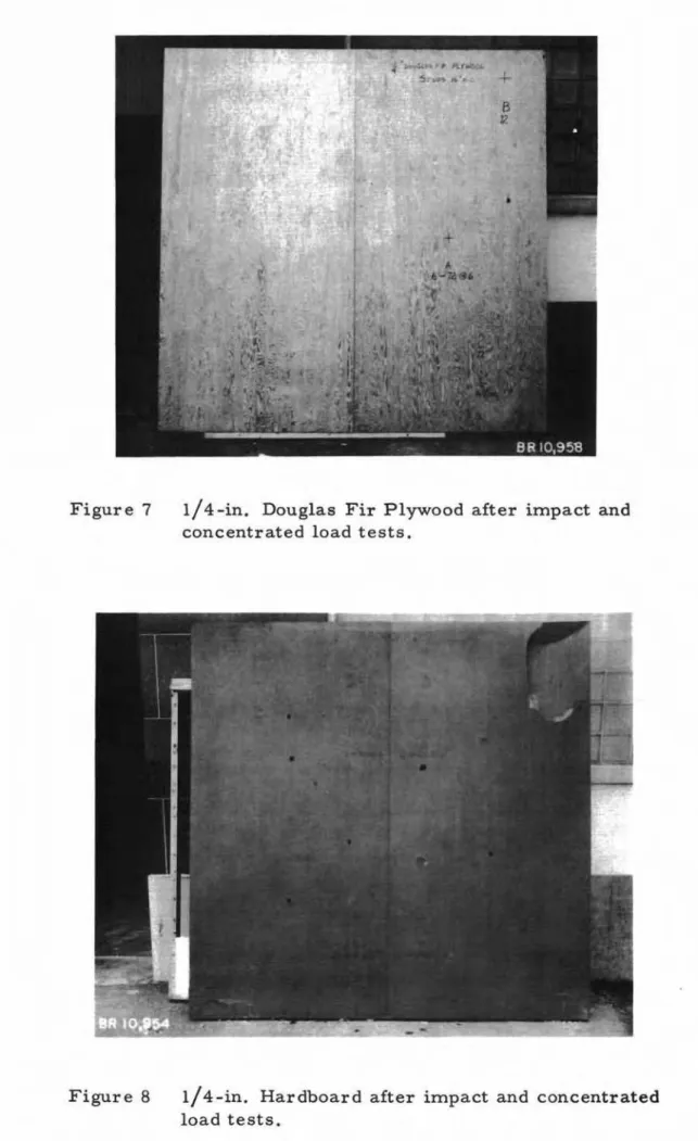
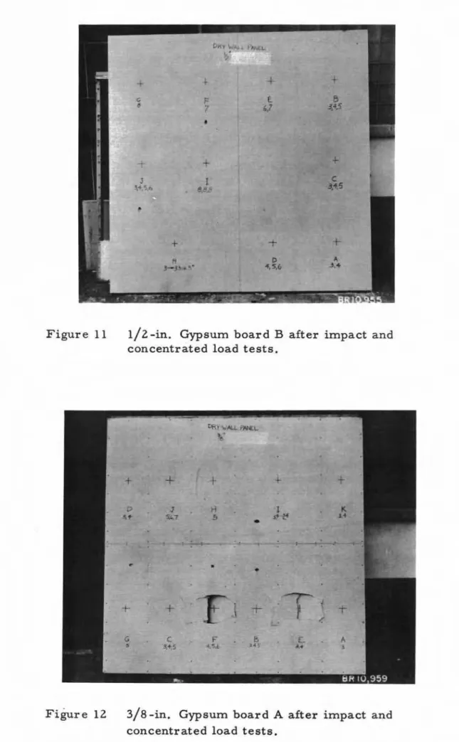
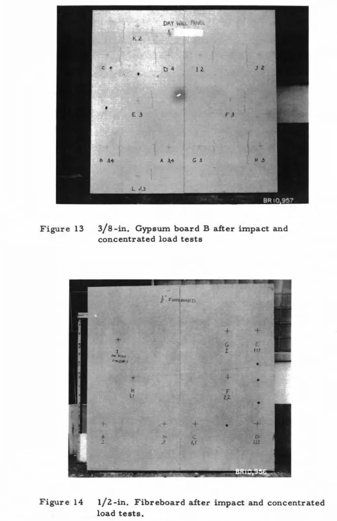
drop height. Figures 7 to 14 show the extent of damage to the wall board
materials. The impact points are clearly marked and the test sequence
and drop heights are indicated by notes on the panels.
The readings, taken from the deflectometer, showed such erratic results that no graphs of instantaneous deflection were plotted.
There are two primary reasons for these inconsistent results: first,
because impact tests were conducted in a variety of locations on the panel the degree of bending and therefore of deflection of both the wall board material and the panel frame itself were widely affected, and
second, the wooden friction clamp on the de£1ectometer rod had a tendency to loos en during a test.
The results of the impact load tests on the individual wall board materials were as follows:
l/4-in. Douglas Fir Plywood - The impact resistance of
the plywood was considerably greater than that of the other wall boards tested. It had high strength in bending and because of its high resilience
it caused the bag and panel to bounce considerably. To overcome this
the corner s of the panel were weighted down with concrete blocks and a Z by 4 was used to replace one of the Z-in. diameter pipe rollers. The strength was so great that one of the plates broke before the plywood did.
l/4-in. Hardboard - This panel consisted of two sheets of
hardboard, one Canadian and the other Swedish, nailed side by side on
the panel. The two behaved generally in the same manner but the
Swedish hardboard appeared ZO to 50 per cent weaker than its Canadian
counterpart. Hardboard had a tendency to crack from the edges of
the sheet, and was much stronger where the material surrounding the
impact area was continuous. The resilience caused the finishing nails
to "pop out" during impact. One of the intermediate studs broke before failur e was reached in one centr al ar ea.
I-in. Plastered Panel - This special 7 - by 8 -ft panel (consisting of 3/8 -In , gypsum lath, approximately l/Z -in. vermiculite base coat, and 1/16 - to 1/8 -In , lime putty surface coat) had a tendency
to crack extensively. The hard, thin layer of lime putty chipped off
In small pieces along these cracks.
liz
-in. Gypsum Board "A" - The sheets of l/Z -in. gypsum wallboard, type "A", were nailed to the studs (spacing=
Z4 in.) in ahorizontal position. When failure occurred, tensile stresses on the
underside of the panel first tore the paper immediately under the impact point, radial cracks developed from this crack, and a large circular
crack approximately Z ft in diameter developed. The relatively small
resilience was almost all contained in the paper.
l/Z -in. Gypsum Board "B" - The gypsum wallboard, type "B ", which was nailed to the studs vertically, behaved similarly to the l/Z-in. board "A", except in two cases where the paper tore along the
studs rather than at the centre (stud spacing = Z4 in.). The residual
3 8-in. G sum Board "A" - This wall panel (stud spacing =
16 in. ) was constructed with the 3 8 -in. gypsum board sheets nailed
in a horizontal position. The 3/8 -in. thick gypsum board was 30 to
40 per cent weaker than the l/Z -in. board. In areas where the
sheets were continuous over studs, failure occurred in the negative bending moment area along the studs, while positive bending caus ed rupture in non -continuous areas.
3/8 -in. Gypsum Board "B" - The 3/8 -In. gypsum board "B" was nailed vertically on studs spaced at 16 in. In comparison with the 3/8 -in. board "A" it was weaker, and also failed along the studs. The different positions of the sheets (i. e., horizontal or vertical) do not seem to account for the strength differences.
liz -in. Fibreboard - This very soft material had little
resilience and was permanently deformed under very small impact
loads. It was the weakest material tested.
(b) Concentrated Load Tests
The results of the concentrated load tests are shown
graphically in Figs. 15 and 16. All curves are the average of at
least three sets of readings.
The following is the list of materials in order of decreasing indentation resistance for load application midway between studs
(failure loads are shown): Material
1/4-in. Douglas Fir Plywood 1/4-in. Canadian Hardboard 1/4-in. Swedish Hardboard I-in. Plastered Panel l/Z -in. Gypsum Board "A"
liz
-In, Gypsum Board "B" 3/8-Iri. Gypsum Board "A" 3/8 -in. Gypsum Board "B" l/Z -i.n, Fibreboard Failure Load 7251b 5471b 3931b 3301b 147 Ib 1341b 107 Ib 115 lb 6Z lbFigur e 15 shows the residual indentation caus ed by load
application midway between studs. Gauge readings were not taken
for the plywood and hardboard because of very high resilience of the
materials. Observations showed that the hardboard was indented
least while the plywood was a close second. Gauge points on the
indenting head were 6 in. apart and any residual deflection caused by bending within that 6 -Ln, span would be recorded as well as the
actual surface indentation. The curves, therefore, probably do not
show the true indentation but rather residual depths that are slightly lar ger than the actual local depr es sion in the material.
The residual set caused by load application directly over
a stud is shown in Fig. 16. The Canadian hardboard showed the
least indentation while the fibreboard was badly indented. The curves
show a wide variation in the depths of indentation of the various sheathings.
DISCUSSION
This series of tests revealed very large differences in
impact and indentation resistance of the various interior wall coverings. Although it is doubtful that an interior wall in normal domestic use would be subjected to forces of a magnitude equal to those applied in the tests on the stronger materials, the results indicated clearly which wallboards were more susceptible to damage.
Since all the materials tested are at present acceptable as interior wall coverings, it must be concluded that impact and indentation resistance cannot, even implicitly, have served in the past as a basis of acceptability, but rather that other factors, such as availability, cost, common practice and perhaps flatness in service, may have led to the present situation.
During the testing a number of pos sible improvements in the
testing technique became evident. Suggestions to this effect are listed
Material Stud spacing, Nailing Location Single Drop Height Variation, in. Remarks
in. of Impact
Starting Increment Height at Impact Height,
Height of Failure in.
Increase
f---1/4" Plywood 16 1 I/Z" Between 6 6 >72 Impact where sheet
Finishing studs continuous over
6" on Edge studs and near edge
lZ" Interior of sheet.
On stud >72
1/4" Canadi- 16 1 l/Z" Between lZ lZ >72 Impact where sheet
an Hardboard Finishing studs continuous over
6" on Edge studs.
lZ" Interior 6 6 54 Impact near edge
-of sheet. 54" .' lowest value. On stud >72
1/4" Swedish 16 1 I/Z" Between 6 6 >72 Impact where sheet
Hardboard Finishing studs continuous over
6" on Edge stud.
lZ" Interior 6 6 30 Impact near edge
- of sheet. 30" lowest value. On stud >72 Plastered 16 Between 6 6 18 panel studs -On stud 6 6 36
I/Z" Gypsum Z4 1 1/4" Between 8 3 I 6 Sheets nailed on
-board A
6" oc studs horizontally.
On stud 3 1 31
l/Z" Gypsum Z4 1 1/4" Between 8 3 1 5 Sheets nailed on
-board B
6" oc studs vertically.
On stud 3 3 33
3/8" Gypsum 16 1 1/4" Between 5 3 I 5 Sheets nailed on
-board A 6" oc studs horizontally. On stud 3 1 Z4 3/8" Gypsum 16 1 1/4" Between Z -board B
6" oc studs Sheets nailed
On stud vertically.
l/Z" Fibre- 16 Z" Between Z
-board Finishing studs
6" oc
SUGGESTIONS AND RECOMMENDATIONS FOR FUTURE TESTS
Several recommendations, made during the tests, are worthy
of consideration before more tests are conducted. These are as follows:
1. A smaller impact weight (say a 30 -lb 6 -in. diameter bag
compared to the standard 60-lb 10 1/2-in. diameter bag) would be more practical, especially for tests on the weaker materials, because the
60 -lb bag made it difficult to differ entiate between the weaker materials. 2. A flat support (say a 2 x 4 laid on its side) should be used to replace one of the 2 -in. diameter pipe rollers during impact load tests
on strong, highly resilient materials. This would reduce the tendency
of the panel to bounce and roll sideways upon impact.
3. For the same resilient materials, standard weights should
be placed on the corners of the panels to keep them from bouncing around during impact.
4. A clamp which would maintain a constant friction force
should be designed for the deflectometer.
5. The wall studs should be kept from bending during indentation
セ・ウエウ by the use of longer weights placed on top of the panel. (During
this test series, when the load was applied the studs deformed; thus the dial gauges on the loading head measured this bending as well as the actual indentation in the sheathing material. )
6. Other tests on the tensile strength of gypsum wallboard
3 "
D
B CC==== ID
:: C\J GA- HOOK FOR LIFTING PURPOSES
B-METAL BLOCK
C-FIXED PIN
D- MOVEABLE PI N
E - WING NUT
F - I" DIAMETER PIPE
G - ROPES SUPPORTING BAG
FIGURE I
)
SET GAUGE MOVEABLE BAR FRICTIONr
CLAMP '---STANO '---: DE FLECTOMETER F A- S'x S' STANDARD PANEL B- SUPPORTING ROLLERSC- CON CRET E BLO CKS
D- SANDBA G (6 0 LBI 101/2" DIA . F LAT BOT TOM )
E-RELEASE BLOCK
F-HOIST ON OVERHEAD CRANE
FIGURE
2
D - HYDRAULIC JACK
E - LOADING HEAD
FIGURE 3
LEGEND
セ IMPACT BETWEEN STUDS
ITID
IMPACT ON STUDS1/4" CANADIAN HARDBOARD 1/4" SWE DI SH HARDBOARD PLASTERED PANEL
liz"
GY PSUM BOARD "A" I/Z"GYPS UM BOARD" B"%"
GYPSUM BOARD" A":Ya"
GY PSU M BOARD "B" '.12" FIBREBOARDo
2 3 4 5DROP HEIGHT IN FEET
FIGURE
5
RESULTS OF IMPACT LOAD TEST
-12 -10
-08
2 PANEL 1/4"PLYWOOD-
10Z
'I/CANADIAN HARDBOARD l -I 1/4" SW EDIS H セ8
-w HARDBOARD I a.. 0 a: 06
I-(J'12"
GYPSU M <{ a..3/e"GYPSU M BOARD "A"
セ
-BOARD "A" 4
RES IDUAL SET BETWEE N STU DS (I N.l
FIGURE
6
RESIDUAL SET AFTER IMPACT BETWEEN
STUDS ( WITHOUT FAILURE)
Figure 8 1/4-in. Hardboard after impact and concentrated load tests.
Figure 9 Figure 10
セ
セ
•
•
/•
(•
•
I-in. Plastered panel after impact and concen-trated load tests .
D f :. ALL • j,
+
• • + o セ L セ , -.
,.. ..セliZ-in. Gypsum board A after impact and concen-trated load tests.
+ F 7
+
J I 3..ALセL\^ e,::!セ + H 3- 3 セ N+
E.o
D " ,5,£,+
B 3,4,5+
Figure 1 1 1/2 -in. Gypsum board B after impact a n d concentrated load tests.
+
+
t-
+
D J H 1 K 3, + 5;"7 .5 s -/.4 34•
[ MZ M セ•
A 3 T L セ Nセ F セNGsLエ+
C 3,<;5 G 5+
Figure 12 3/8-In, Gypsum board A after impact and
Figure 14 1/2 -In, Fibreboard after impact and concentrated load tests.
250
NOTE
1/4" DOUGLAS FIR PLYWOOD F= 725·
1/4" SWEDISH HARDBOARD F= 393:lt 1/4" CANADIAN HARDBOARD F = 547* F=FAILUHE LOAD
.--BD."B" F= 115# F=
107#112"
FI BREBOARD F = 62*'---
---'-<:1/z'GYPSUM BD."A" F = 147# 150OL-_ _
...L..._ _----L ..L.-_ _--L- " - -_ _....l...----I 50 100 Cl <! 200 o ....J Cl l.LJ セ <! 0:: セ Z l.LJ U Z o u ·01 . 02 ·03 ·04 '05RESIDUAL INDENTATION (IN)
·06
FIGURE
15
CONCENTRATED LOAD TEST ON
(LOADING BETWEEN STUDS)
---.----
-
---
-
--MMセ ...---NNNNNNMセ...
..
...-»>
500 400800
i Iiセ[
,-.: I ./
./
/.
;'.
-:
..
セセMMM
/I /
1/'
./;//
1t/i //
: . ! /
1
I
J:.!'
<.... _...-
1/4"CANADIAN HARDBOARD " 'セO
- " - '/4"SWEDISH HARDBOARD/
: 'I' /
:I _
---
'/4"DOUGLAS FIR PLYWOOD3/e" GYPSUM BOARD .IB"It
セjB
,...
!
-'-
'/2"GYPSUM BOARD "A"Q
W セ
I _ ....- 3/e" GYPSUM BOARD "A"I,·n /
- - -
'/2"GYPSUM BOARD "B": 1/1/ "
PLASTERED PANEL F=300300
fi
f
j-
---
l/z"FI BREBOARD:.h :'
/
/' //.
200
,,11: .•
iセャセAO
.,
.
,if/I
100lil
.1fj..
i' :
600
700
Cl « o ...J m ...J Cl I.LJI-«
a:: I-:z I.LJ c...> :z o c...> -01 . 02 ·03 ·04 ·05RESIDUAL INDENTATION (IN)
·06
FIGURE 16
CONCENTRATED LOAD TEST
(LOADING ON STUDS)
8R. 2G>o:!>-7