Cement As a Waste Form for Nuclear Fission
Products: The Case of ⁹⁰Sr and Its Daughters
The MIT Faculty has made this article openly available. Please sharehow this access benefits you. Your story matters.
Citation Dezerald, Lucile et al. “Cement As a Waste Form for Nuclear Fission Products: The Case of ⁹⁰Sr and Its Daughters.” Environmental
Science & Technology 49, 22 (October 2015): 13676–13683 © 2015 American Chemical Society
As Published http://dx.doi.org/10.1021/ACS.EST.5B02609 Publisher American Chemical Society (ACS)
Version Author's final manuscript
Citable link http://hdl.handle.net/1721.1/117473
Terms of Use Article is made available in accordance with the publisher's policy and may be subject to US copyright law. Please refer to the publisher's site for terms of use.
Cement as a waste form for nuclear fission products: the case of
190
Sr and its daughters
2Lucile Dezerald,1, 2 Jorge J. Kohanoff,3 Alfredo A. Correa,4 Alfredo 3
Caro,5 Roland J.-M. Pellenq,1, 2, 6 Franz J. Ulm,1, 2 and Andr´es Sa´ul∗1, 2, 6
4
1Department of Civil and Environmental Engineering, 5
Massachusetts Institute of Technology,
6
2MultiScale Material Science for Energy and Environment, UMI 3466 CNRS-MIT, 7
77 Massachusetts Avenue, Cambridge CA 02139, USA
8
3Atomistic Simulation Centre, Queen’s University Belfast, 9
Belfast BT7 1NN, United Kingdom
10
4Condensed Matter and Materials Division, 11
Physical and Life Sciences Directorate,
12
Lawrence Livermore National Laboratory, Livermore, California 94550, USA
13
5Los Alamos National Laboratory, Los Alamos New Mexico 87545, USA 14
6Aix-Marseille University, CINaM-CNRS UMR 7325 15
Campus de Luminy, 13288 Marseille cedex 9, France
16
Abstract
17
One of the main challenges faced by the nuclear industry is the long-term confinement of nuclear
18
waste. Because it is inexpensive and easy to manufacture, cement is the material of choice to store
19
large volumes of radioactive materials, in particular the low-level medium-lived fission products.
20
It is therefore of utmost importance to assess the chemical and structural stability of cement
21
containing radioactive species. Here, we use ab-initio calculations based on density functional
22
theory (DFT) to study the effects of 90Sr insertion and decay in C-S-H (calcium-silicate-hydrate)
23
in order to test the ability of cement to trap and hold this radioactive fission product and to
24
investigate the consequences of its β-decay on the cement paste structure. We show that 90Sr is
25
stable when it substitutes the Ca2+ions in C-S-H, and so is its daughter nucleus90Y after β-decay.
26
Interestingly,90Zr, daughter of90Y and final product in the decay sequence, is found to be unstable
27
compared to the bulk phase of the element at zero K but stable when compared to the solvated
28
ion in water. Therefore cement appears as a suitable waste form for90Sr storage.
INTRODUCTION
30
Long-term confinement of radioelements produced by nuclear fission is one of the main
31
challenges faced by the nuclear industry. The primary focus of the nuclear waste storage
32
research has long been oriented towards host materials that can handle the large structural
33
damage induced by the high-energy α-decay of actinides.1,2 However, the need for optimizing
34
the vitrification process of actinides1 and for increasing the capacity of repositories3 has 35
prompted the investigation of other forms of containers specifically targeted at low- and
36
medium-level waste. Such containers became urgently needed after the Fukushima disaster,
37
where large volumes of contaminated soils, water and buildings had to be quickly handled.4–7 38
The main concern lies in the management of the medium-lived β−-emitter fission products,
39
137Cs and90Sr.4,5 These represent the largest fraction of the nuclear waste by activity ,8 40
and have been found in the surrounding areas and in the cooling water of the damaged power
41
plants.4,5 They present important health risks: 137Cs β− decay is followed by a hazardous
42
γ emission, while 90Sr can contaminate the animal and human population due to its ability 43
to replace the isovalent Ca ions that constitute bones and teeth (hence the name bone
44
seeker). This is particularly dangerous as β-emission in the bone produces a low-energy
45
electron cascade that can reach stem cells in the bone marrow, this being a major cause of
46
leukaemia.
47
β− decay produces modifications of the host matrix chemistry and can also influence its
48
mechanical properties. The three main processes following β-decay are: (1) the emission of
49
the β electron at MeV energies, (2) the recoil of the transmuted nucleus with kinetic energies
50
in the eV range due to conservation of momentum, and (3) the electronic rearrangement
51
around the transmuted nucleus due to the sudden increase in nuclear charge (Z → Z + 1).
52
All of these processes interact with the host in different ways.1,9–11 Recent theoretical studies 53
of the effects of transmutation due to β− decay of 137Cs and 90Sr in ceramics and oxides12
54
showed important chemical and structural modifications of the host material in the case
55
of radioparagenesis11,13 in which a solid-state daughter phase is derived radiogenically by
56
a parent phase. These studies enable the design of waste forms with improved mechanical
57
properties by means of transmutation, thus opening a promising avenue for long-term nuclear
58
waste containment. A different, although related matter is the assessment of the aging of
59
materials partially contaminated by hosting nuclear waste, which is the main focus of the
present work.
61
Here we investigate the local effects of90Sr contamination and transmutation on cement. 62
90Sr (half-life 28.79 years) undergoes two successive β−decays to90Y (half-life 64 hours), and 63
to90Zr (stable). Compared to specifically designed glass or ceramic nuclear waste containers, 64
cement is inexpensive, easy to manufacture, easy to formulate by mixing with other materials
65
such as blast furnace slag,14 and it benefits from centuries of use and decades of research
66
related to the civil engineering industry. This makes cement the primary candidate for large
67
volumes of low-level nuclear waste storage in post-accidental conditions. So far, most of the
68
research on irradiated cement has focused on its ability to capture radioelements, and on
69
their leaching from cement containers.8,15–21 As mentioned above, 90Sr capture in cement is 70
very likely because of Ca-Sr isovalence, Ca being present in C-S-H (calcium-silicate-hydrate),
71
which is the principal binding product of cement hydration.22–24 Although recent atomistic 72
simulations showed that 90Sr capture by C-S-H does not modify the elastic properties of
73
cement,25 the consequences of 90Sr transmutation via β− decay on C-S-H structure and 74
chemical properties are still largely unknown.
75
In this work we investigate the consequences of 90Sr transmutation in C-S-H using calcu-76
lations based on Density Functional Theory (DFT), which is an appropriate tool to account
77
for the electronic and chemical properties of the cement paste as well as those of the
inves-78
tigated radionuclides. The chemical and physical mechanisms at stake in 90Sr capture were 79
investigated by substituting Ca atoms in the atomistic model of C-S-H proposed in
Refer-80
ences [26–28]. 90Sr was then successively replaced by its daughter nucleus, 90Y and 90Zr, to 81
study the stability of these elements in cement paste. DFT molecular dynamics (DFMD)
82
simulations were then performed to investigate the possible chemical and structural
modifi-83
cations induced locally in C-S-H contaminated by90Sr and its successive transmutations. 84
METHODOLOGY
85
C-S-H, the principal binding phase responsible of the strength of cementitious materials,
86
precipitates as nanoscale clusters when mixing water with di-calcium (C2S) and tri-calcium 87
silicate (C3S). Given its complex structure and composition, the atomic structure of C-S-H 88
has traditionally been based on Taylor’s postulate that C-S-H is a structurally imperfect
89
layered hybrid of two natural minerals,29 tobermorite of 14 ˚A interlayer spacing30 and 90
jennite.31 These minerals reproduce the laminar structure of C-S-H where calcium ions are 91
located between layers of silicate chains. An overview of the tobermorite and jennite-based
92
C-S-H models used in the literature is given in Refs. [32 and 33]. However, limitations of
93
these models emerged when it became possible to further characterize experimentally the
94
C-S-H molecular composition, notably the average calcium to silicon ratio (C/S = 1.7) and
95
the density of the C-S-H particle (2.6 g/cm3).34–37 These values cannot be obtained from 96
either tobermorite 14 ˚A (C/S = 0.83 and 2.18 g/cm3) or jennite (C/S = 1.5 and 2.27
97
g/cm3). A solid solution model proposed recently38 corrects most of these problems. 98
The atomic structure for C-S-H used in this work has recently been proposed in order
99
to bridge the gap between atomic-scale simulations and experiments.26–28 It is presented in
100
Fig. 1 and was generated following the procedure reported in Ref. [26].
101
102
Figure 1. (color online) Schematic representation of the C-S-H structure. Hydrogen atoms are in
103
white, oxygen atoms in red, calcium in yellow, and Si in blue. The corner sharing SiO44−tetrahedra
104
forming the silicate chains are also shown.
This model was shown to reproduce accurately both the structural and chemical
prop-106
erties of C-S-H. Among other properties, water content, silica chain lengths, and pair
dis-107
tribution functions were compared satisfactorily to small angle neutron scattering (SANS),
108
solid-state nuclear magnetic resonance (NMR) and x-ray diffraction (XRD) experiments,
re-109
spectively. The cell contains 501 atoms and has the chemical composition Ca72Si44O235H150, 110
with a C/S ratio of 1.64 and a density of 2.33 g/cm3 in very good agreement with experimen-111
tal data.34–37 Figure 1 shows the silicate chains formed by corner sharing SiO44− tetrahedra.
112
These chains, which form the characteristic layered structure of C-S-H, have been randomly
113
broken to obtain the desired C/S ratio.26–28 It can also be seen that the Ca2+ ions appear in
114
two distinct environments: intralayer and interlayer. Water, in the form of H2O molecules 115
and OH− groups, is present in the interlayer space.
116
First-principles electronic structure calculations were performed within the DFT
frame-117
work using the Quantum-espresso plane-wave code.39We used the Perdew-Burke-Ernzerhof 118
generalized gradient approximation (PBE-GGA)40 and ultrasoft pseudopotentials with
ex-119
plicit semi-core electrons. The plane-wave cutoff for the Kohn-Sham orbitals was set to 80
120
Ry and all the calculations were performed at constant volume with a single k-point (the
121
Γ-point). Residual forces on the atoms after geometric relaxation were smaller than 10−3
122
Ry/a0. 123
We first performed a 1.2 ps DFMD simulation at 300 K to check the local stability of
124
the C-S-H structure used. We then performed a set of DFMD simulations to study possible
125
displacements of the substitute radioelements in the cement matrix.
126
Given the computational load of DFMD calculations, the latter were performed for only
127
one of the 72 Ca sites (site number 56, interlayer, indicated in Fig. 1). These simulations
128
were aimed at verifying that the preferred site for the substituting atoms corresponded to
129
the site previously occupied by the Ca ion. When this was not the case, the simulations
130
allowed us to investigate the structural modifications induced by 90Sr insertion and decay 131
in C-S-H.
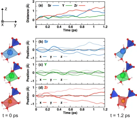
132
RESULTS
133
Substitution and decay of 90Sr in Ca sites. C-S-H contamination was investigated
134
by substituting one by one each Ca atom by Sr. The chemical effects of90Sr transmutation 135
via β− decay in C-S-H were then studied by substituting Ca with Y and Zr, successively.
136
The C-S-H cell after substitution, denoted Can−1X where X stands for Sr, Y or Zr, has the
137
chemical composition Ca71XSi44O235H150. Each substitution is followed by relaxation of the 138
atomic positions. The substitution energy ∆EX(i) calculated with respect to the bulk 139
phases of the elements at 0 K is defined as:
140
∆EX(i) = ECan−1X(i)− ECan + E bulk
Ca − EXbulk (1)
where ECan−1X(i) is the energy of the cell containing element X at site i, ECan is the energy
141
of C-S-H before substitution, and Ebulk
X are the energies of the bulk phases: face-centered 142
cubic for Ca and Sr, and hexagonal close-packed for Y and Zr. The calculated substitution
143
energies for Sr, Y and Zr in each one of the 72 Ca sites of the simulation cell are presented
144 in Fig. 2. 145 -1 0 1 2 3 0 10 20 30 40 50 60 70 ∆ EX (eV) Site number (a)Sr 0 10 20 30 40 50 60 70 Site number (b)Y 0 10 20 30 40 50 60 70 -1 0 1 2 3 Site number (c)Zr 146
Figure 2. (color online) Substitution energies for (a) Sr, (b) Y, and (c) Zr (circles) in the 72 Ca
147
sites calculated with respect to the bulk phases at 0K. The vertical lines separate the first
148
48 sites corresponding to intralayer sites trapped between silicate chains and the remaining 24 sites
149
(number 49 to 72) corresponding to the interlayer area. The horizontal lines stand for the average
150
substitution energy value, calculated separately for the intralayer and interlayer.
151
Figure 2(a) shows the results for Sr. As expected from the isovalence between Sr and
152
Ca, the substitution energy is generally low (0.15 eV on average), with 7 negative values.
153
Negative ∆ESr values indicate sites where Sr is more stable than Ca, and will tend to 154
substitute it, thus contaminating the sample. To further analyze the data, we divided
155
Fig. 2(a) into two sections marked by a vertical line: the first 48 sites correspond to intralayer
156
Ca sites trapped between silicate chains and the remaining 24 sites (number 49 to 72)
correspond to the interlayer area, where the Ca ions co-exists with water molecules and OH−
158
groups. We also show in Fig. 2(a) the average substitution energy calculated separately for
159
the intra and interlayer with a horizontal blue line; the substitution energies for90Sr are, on 160
average, lower in the interlayer (0.08 eV) than in the intralayer (0.19 eV).
161
It is interesting to note here that due to the configurational entropy contribution to the
162
free energy, solution energies of this order of magnitude imply quite a large solubility limit
163
even at room temperature. A regular solution model with a solution energy of 0.08 eV gives,
164
for example, a solubility at room temperature of 4%, thus providing an order of magnitude
165
of the amount of Sr that can be incorporated into cement.
166
These results are in good agreement with experimental observations showing that Sr
167
uptake in cement occurs preferably by Ca substitution in C-S-H.22,23 They also showed that
168
the Sr2+-Ca2+ exchange might occur in the interlayers of the C-S-H phases.23 The presence 169
of other isotopes of Sr arising from the raw materials (86Sr and 87Sr) in standard cement
170
should not modify this mechanism since the quantity is negligible (approximately 0.1%).
171
Table 1. Average substitution energy ∆EX calculated relative to the bulk phases at 0K
172
(columns 2 to 4) and to the hydrated forms of the ions (columns 5 to 7) (eV) on all the
173
72 substitution Ca sites and separately on the 48 intralayer sites and on the 24 interlayer sites.
174
Relative to the bulk phase at 0 K Relative to the hydrated forms of the ions
Total Intralayer Interlayer Total Intralayer Interlayer
Sr 0.15 0.19 0.08 0.23 0.27 0.16
Y 0.05 0.11 -0.09 -3.32 -3.26 -3.46
Zr 2.34 2.49 2.04 -6.43 -6.28 -6.73
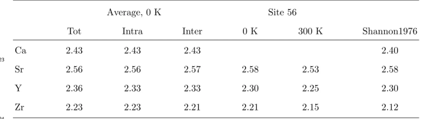
175
176
In order to investigate the chemical effects of 90Sr β− decay on C-S-H structure, we 177
calculated the substitution energy of Y relative to the bulk phases at 0 K in all 72 Ca
178
site. The results are presented in Fig. 2(b) and the calculated average substitution energies
179
are gathered in Table 1. Fig. 2(b) shows that the substitution energy of Y is generally lower
180
than that of Sr, with a larger dispersion and an average value of 0.05 eV. Overall, 28 sites
181
substituted with Y display a negative ∆EY. Y is consequently more stable in C-S-H than 182
Sr, which could seem surprising because, with a theoretical charge of 3+, Y is not isovalent
183
with Ca. Nevertheless, it has been shown experimentally that other 3+ charged metals (Nd,
Cm and Eu) can be accommodated by substitution of Ca in C-S-H.41–44 For Y, the average 185
substitution energy is lower but still positive in the intralayer region (0.11 eV), and it is now
186
negative in the interlayer spacing (-0.09 eV). We also notice that the difference between the
187
average substitution energy in the intra and interlayer regions is larger for 90Y (0.20 eV)
188
than for 90Sr (0.11 eV). 189
The substitution energies of 90Zr, daughter nucleus of 90Y also through β− decay, using
190
the same bulk references, are given for the 72 sites in Fig. 2(c) and Table 1. Contrary
191
to Sr and Y, the calculated energies are all positive, large and widely dispersed around the
192
average value of 2.34 eV, which is more than one order of magnitude larger than that of Sr.
193
Fig. 2(c) shows again an enhanced stability upon substitution in the interlayer relative to
194
the intralayer region, while the energy difference between intra and interlayer substitution
195
is the largest (0.45 eV).
196
The substitution energies that we presented here use the energies of the bulk phases
197
at 0 K as a reference. Another possibility would be to use the solvation energy of the
198
corresponding hydrated forms of the ions. To convert from the elemental forms to the
199
hydrated ones, one should add to the bulk energies Ebulk
X in Eq. (1) two positive
200
quantities, the corresponding cohesion and ionization energies and a negative one, the
201
hydration energy of the corresponding ions. Using the values reported in Ref. [45] for the
202
latter, we have found that the new reference shifts the points in Figures 2(a), 2(b), and 2(c)
203
by 0.08, -3.37, and -8.77 eV respectively. With respect to the hydrated ions, the average
204
substitution energies become 0.23, -3.23, and -6.43 eV (see Table 1).
205
The most important difference is the highly negative value of the substitution energies
206
for Zr originated by the unstable character of the hydrated forms of Zr4+ which has been 207
reported to be stable only in dilute solutions with a pH below 0.46 208
This is an important result meaning that substitution of Ca by Zr is unfavored
209
when compared to the bulk phases at 0 K but the substitution is very likely when
210
compared to the hydrated forms in water. However, in order to state a definitive
211
conclusion on the most suitable adsorption site for Zr a systematic study of all possible
212
compounds and coordination complex has to be performed. Such study is beyond the scope
213
of the present paper.
214
Finally, we have also verified that Sr in C-S-H prefers to substitute Ca rather than Si
215
(present in the silicate chains). Substitution energies with respect to the bulk phases
obtained for Sr replacing Si are around 4 eV, which are 10 times larger than those obtained
217
when Sr replaces Ca, thus rendering this process extremely unlikely. This is expected from
218
the charge imbalance locally originated by such a substitution.
219
Effects of temperature on contaminated C-S-H. To further investigate the effect of
220
90Sr contamination and decay on the structure of C-S-H, we performed DFMD simulations 221
at 300 K for 1.2 ps. The goal of this is to investigate if the presence of Sr and its daughter
222
nuclei Y and Zr can lead to structural modifications of the cement paste, or if they are
223
likely to stay in former Ca sites as assumed above. Given the computational cost of such
224
calculations, we focused on a single Ca site, number 56 in our notation, which is situated
225
in the interlayer spacing. This site is a good candidate to test our hypotheses. Since its
226
substitution energy is average for Sr and larger than average for Y and Zr, the daughters
227
are likely to migrate.
228
For the DFMD simulations, we have used a temperature control based on velocity
rescal-229
ing. In this scheme, the velocities are rescaled if the average temperature and the target
230
temperature of the system differ in more than a certain tolerance, which here was set to
231
50K.
232
The thermal relaxation of Sr56, Y56 and Zr56 during the simulated time range was
233
investigated by studying the displacements of the three substitute atoms. The results are
234
presented in Fig. 3. The displacements were found to be rather small, not exceeding 1.5 ˚A,
235
as one would expect in such short simulations. Fig. 3(a) shows that Sr56 (in blue) travels a
236
maximum distance of 0.5 ˚A before 0.6 ps, after which it starts moving away from its original
237
position rather quickly before stabilizing again. Y56 does not move much away from its
238
original position. The maximum total displacement calculated remains under 0.5 ˚A over the
239
complete DFMD simulation. The displacement of Zr56 (orange) is qualitatively different
240
from Sr56 and Y56. Not only it is larger, but it increases monotonically from the start of
241
the simulation, thus suggesting that Zr is not stable in the interlayer Ca sites.
242
The distance traveled by Sr56, Y56, and Zr56 can be decomposed into the contributions
243
along the x, y and z directions, as shown in Fig. 3(b), (c), and (d). We also show in Fig. 3
244
the coordination polyhedra around Sr56, Y56, and Zr56 at t = 0 ps (left) and 1.2 ps (right).
245
Figure 3(b) shows that the large increase of distance starting at 0.6 ps in Sr56 is mainly
246
due to displacements of equal amplitudes in the y and z directions, i.e. along the [011]
247
direction which is perpendicular to the silicate layers (see Fig. 1). The variations in the x
direction are small after thermalization, and stabilize close to zero after 0.4 ps. The main
249
difference in the coordination polyhedra is the elimination of one of the hydration waters.
250
251
Figure 3. (color online) (a) Distance traveled by Sr56 (blue), Y56 (green) and Zr56 (orange) as a
252
function of time; and evolution of the position of (b) Sr56, (c) Y56, and (d) Zr56 with time at 300
253
K, along the x (plain lines), y (dashed lines), and z (dotted lines) direction. The corresponding
254
coordination polyhedra formed by X56-O are shown at t = 0 ps and t = 1.2 ps respectively on the
255
left and right of (b) to (d)).
256
The same is valid for Zr56 (see Fig. 3(d)), where the largest displacements are also along
257
the [011] direction (see Fig. 3(d)), although in this case the displacement continues increasing
258
over time. In consequence, the surroundings of Zr56 are modified during the simulation, the
259
major difference being that the coordination evolves from one SiO44− tetrahedron,
260
two hydration waters and two OH groups at t = 0 ps to two SiO44− tetrahedra
261
and three OH groups at t = 1.2 ps (see Fig. 3(d)).
262
Figure 3(c) shows that the total displacement calculated for Y56 is due to small
oscilla-263
tions of this atom around its original position in the three directions, due to thermal motion,
and no important modification is visible on the Y56-O polyhedron. The similarity between
265
the O-Ca and O-Y bond lengths (see below) is certainly at the origin of this result.
266
The configurations reached after 1.2 ps of DFMD simulation were relaxed back to 0 K
267
using the same convergence criterion on the total energy and forces used for the substitution
268
energy calculations. This calculation was performed in order to verify whether the ground
269
state energies obtained after the thermal rearrangement are similar to those displayed in
270
Fig. 2. Before the DFMD simulation, the Y-Sr energy difference was 0.37 eV and the Zr-Sr
271
energy difference was 2.82 eV, i.e. site 56 did not exactly respect the global trend according
272
to which Y is slightly more stable than Sr. After the 1.2 ps DFMD simulation and quenching
273
back to 0 K, we found that the substitution energy for site 56 reverts, now conforming to
274
the hierarchy previously calculated: it is lowest for Y, small for Sr and large for Zr. The
275
energy differences are now -0.05 eV for Y-Sr and 2.88 for Zr-Sr, thus validating the previous
276
approach.
277
DISCUSSION
278
Pair distribution. In order to investigate the physical origin of the relative stability of
279
Sr, Y, and Zr in the cement paste, we calculated the pair distribution function (PDF) for
280
the X-O bonds at 0 K (X = Ca, Sr, Y, Zr). We compare the PDF with the average bond
281
lengths obtained by Shannon from an extensive compilation of crystallographic data.47,48 282
The pair distributions are shown as solid black lines in Figures 4(a) to (d).
283
The PDF for Ca-O is shown in Fig. 4(a) along with the value of 2.40 ˚A tabulated by
284
Shannon for the Ca-O bond length, which is indicated by a vertical line. The average Ca-O
285
bond length was calculated to be 2.43 ˚A, in good agreement with the tabulated value. These
286
values are reported in Table 2.
287
The Sr-O PDF is shown in Fig. 4(b). Its maximum is shifted to larger distances compared
288
to the Ca-O pair distribution, in good agreement with the tabulated value. The
correspond-289
ing Sr-O bond length, 2.56 ˚A, is also close to the tabulated value of 2.58 ˚A. The Y-O pair
290
distribution shown in Fig. 4(c) is shifted towards shorter distances compared to the Ca-O
291
pair distribution. The bond length was found to be 2.36 ˚A, which is slightly larger than the
292
tabulated bond length of 2.30 ˚A. The 0 K Zr-O bond length is the shortest (2.23 ˚A) and
293
displays the largest discrepancy with the tabulated value of 2.12 ˚A. This can be correlated
to the large substitution energies with respect to the bulk phases found for Zr in the 295 previous section. 296 0 5 10 1.8 2 2.2 2.4 2.6 2.8 3 gij (r) Distance (Å) (d)Zr <X−O>, T = 0 KX56−O, T = 0 K X56−O, T = 300 K 0 5 10 gij (r) (c) Y 0 5 10 gij (r) (b)Sr 0 5 10 gij (r) (a) Ca 297
Figure 4. (color online) Pair distribution functions for the O- (a) Ca, (b) Sr, (c) Y, and (d) Zr
298
bonds calculated on average for all sites at 0 K (black lines), for site 56 at 0 K (solid colored lines),
299
and for site 56 at 300 K (colored dotted line). Cubic splines have been used to smooth the pair
300
distribution functions.
301
The pair distributions for the intralayer and interlayer sites do not show substantial
302
differences. To illustrate this point, we report in Table 2 the average bond length for these
303
two regions. The maximum difference calculated between the intra and interlayer X-O
304
distances is 0.02 ˚A for Zr, which is very small compared to differences among elements and
305
hence does not explain the general preference for Ca substitution in the interlayer region.
306
In Figures 4(b) to (d) the colored lines show the pair distributions calculated for the X56-O
307
bond at two different temperatures: 0 K (solid colored lines) and 300 K, averaged over the
308
stable 1 ps part of the DFMD simulation (dashed colored lines).
309
The pair distribution for Sr56-O at 0 K (Fig. 4 (b)) is close to the average Sr-O pair
310
distribution resulting in bond lengths that are similar (see Table 2). The same applies to
the pair distributions and bond lengths calculated for site 56 replaced by Y and Zr at 0 K,
312
thus confirming that site 56 is a good candidate to represent the average properties of these
313
atoms in C-S-H.
314
Table 2. X-O bond lengths in the C-S-H structure. The first three columns report the average bond
315
length calculated on all sites (Total) and separately in the intralayer (Intra) and in the interlayer
316
(Inter) sites at 0 K. The next two columns give the X-O bond length calculated for atom X in
317
site 56 at 0 K and at 300 K. The last column gives the values obtained from Table 1 of Ref. [48]
318
(Shannon1976). For easy of comparison we consistently used the reported values for coordination
319
number VI and the formal charges 2+, 2+, 3+, and 4+ for Ca, Sr, Y, and Zr respectively. We did
320
not take into account the distortion of the coordination polyhedra or the bond length distribution.
321
All the values are given in ˚A.
322
Average, 0 K Site 56
Tot Intra Inter 0 K 300 K Shannon1976
Ca 2.43 2.43 2.43 2.40 Sr 2.56 2.56 2.57 2.58 2.53 2.58 Y 2.36 2.33 2.33 2.30 2.25 2.30 Zr 2.23 2.23 2.21 2.21 2.15 2.12 323 324
The stability of the contaminated C-S-H structure with temperature was investigated by
325
calculating the pair distributions for the X56-O bonds on average at 300 K (dashed colored
326
lines on Figures 4(b) to (d)), and comparing them to the pair distributions obtained at 0 K
327
(solid colored lines). A general broadening of the PDF due to the temperature is visible on
328
all three figures. A slight shift to shorter distances is also observed, which results in shorter
329
average bond lengths (see Table 2). This result can be due to the ability of the mobile H2O 330
molecules and OH− groups from the interlayer to rearrange and form shorter bonds with
331
the substitutional atom under the effects of temperature.
332
Interestingly the average bond length of Zr56-O at 300K is very close to the tabulated
333
value of 2.12 ˚A. In the beginning of the DFMD simulation, Zr56 is located in the interlayer
334
spacing, surrounded by water molecules and OH− groups. Then, Zr56 migrates under the
335
effects of temperature so that, after 0.5 ps, two of the seven nearest O atoms belong to
336
silicate chains (SiO44− tetrahedron). Based on the latter observation and on the isovalency
of Zr with Si, it is natural to wonder whether or not it is convenient for Zr to substitute Si
338
instead of Ca atoms in C-S-H. We investigated this possibility by substituting Zr for Si in
339
seven (out of 44) sites. The calculated energies with respect to the bulk phases were
340
all negative, varying from −2.15 eV to −0.41 eV, with an average value of −1 eV. These
341
energies are much lower than the ones reported in Figure 2(c), and indicate that Zr will
342
certainly stabilize by interfering with the layered structure characteristic of C-S-H. Similar
343
conclusions have been found for the uptake of other 4+ charged metals (Np, Th)24,49 (Sn)50
344
in C-S-H. More firm comparisons however require further investigation, e.g. via DFMD
345
simulation over longer time scales using classical force fields to overcome the time-scale
346
limitations imposed by the first-principles description of the interactions.
347
Analysis of the charges. In order to analyse the bonding characteristics we have
348
calculated the Bader charges51for the configurations relaxed at 0 K using the Bader Charge
349
Analysis tool.52 In this method the atomic charge is defined as the nuclear charge minus the 350
integral of the electronic density in a well-defined volume around the atom. The obtained
351
charges are systematically smaller than the expected formal charges. The more ionic the
352
bond the closer the Bader charge to the formal charge. In this way we obtained 72 values
353
of the effective charge for Ca, Sr, Y and Zr. The average effective charges for all elements
354
are reported in Table 3.
355
Table 3. Average effective charge calculated on all sites (Tot) and separately in the intralayer
356
(Intra) and in the interlayer (Inter) sites. Charge of site X56 at 0 K and 300 K. The theoretical
357
charge for each element is given for information in the first column. All charges are expressed in
358
the elementary charge unit e.
359
Average Site 56
Tot Intra Inter
Ca2+ 1.60± 0.04 1.59 1.61 1.60 Sr2+ 1.62± 0.04 1.61 1.63 1.66 Y3+ 2.22± 0.11 2.21 2.23 2.22 Zr4+ 2.28± 0.41 2.25 2.33 2.15 360 361
Ca and Sr are found to be isovalent, as expected, with an effective charge of approximately
362
1.6e on average. This charge is close to the formal charge of these elements, which means
that the bonding of these systems is ionic, as expected. Y in Ca sites have an average
364
charge of 2.22e, which suggests that Y donates (on average) a large part of its valence
365
electrons, exhibiting a charge state that is intermediate between the 2+ corresponding to
366
the substituted atom, and its own ionic charge of 3+, suggesting a more covalent bonding
367
for this radioelement. This results in a slightly lower substitution energy for Y than that of
368
Sr. Interestingly, Zr has an average charge of 2.28e, similar to that of Y meaning significant
369
covalency in this system. As the Zr charge in cubic ZrO2 is 2.52e, the smaller average value 370
of the charge means that despite the energy relaxation, the substitution sites originally
371
optimized for Ca2+ do not have enough states available in the neighboring oxygen atoms to
372
accept more electrons. This, combined with the pair distribution analysis, could explain the
373
large substitution energies of Zr in Ca sites.
374
To understand the general preference for substitution in the interlayer we report in Table
375
3 the average effective charge calculated separately in the intra and interlayer regions. There
376
is a small but systematic increase of the Bader charges in the interlayer sites with respect to
377
the intralayer ones. This can be explained by the conspicuous presence of oxygen in the form
378
of mobile OH−groups in the interlayer. These can bind more easily to the substitutional
379
ions, whereas in the intralayer the neighboring oxygens belong to the silicate chains and are
380
thus less prone to accept electrons and stabilize the ions.
381
Finally, we note that the difference between inter and intralayer average effective charges
382
increases along the radioactive decay sequence, from 90Sr to 90Zr. Indeed, the difference 383
between the intralayer and interlayer average charge is the smallest for Sr and Y (around
384
0.02e) and four times larger for Zr (0.08e). This result correlates with the substitution
385
energy difference between the intralayer and the interlayer regions that also increases along
386
the same decay sequence, as pointed out in the Results section. Similarly, the dispersion
387
around the average value is the smallest in Sr, intermediate in Y and the largest in Zr, for
388
both the substitution energies (see Fig. 2) and the Bader charges (see Table 3).
389
Environmental implications of the study. Ab initio calculations and DFMD
simula-390
tions were performed to study90Sr contamination and transmutation in C-S-H, the principal
391
binding hydration product of cement. 90Sr and its daughter radionuclide 90Y were found to 392
be stable in the cement paste, with a general preference for substituting Ca in the
inter-393
layer sites, where water enhances the possibilities for atomic bonding and charge transfer.
394
This suggests that cement could be a good material to store the intermediate-half-life fission
product 90Sr, even in large concentrations. A mean field estimation gives a solubility limit 396
of the order of 4% at room temperature, i.e., three 90Sr out of 72 Ca sites. It could be 397
relevant in the context of nuclear waste storage under accidental conditions, for example in
398
the Fukushima case where, to the best of our knowledge, a solution to the problem of storing
399
the highly concentrated 90Sr after extraction from the emergency reactor cooling water has 400
not been found yet.
401
The present work also showed that 90Zr (stable daughter nucleus of 90Y) is not stable 402
in Ca sites when the bulk phase of the corresponding elements at 0K is used as reference
403
but stable when the hydrated form of the corresponding ions is used. The low substitution
404
energies found for 90Zr in Si sites indicate that 90Zr could interfere with the silicate layers.
405
Consequences of this result, such as possible modification of C-S-H mechanical properties
406
by 90Zr migration or structural damage, should be further investigated and could benefit 407
from the use of other simulation techniques such as classical force-field molecular dynamics
408
simulations that can reach time scales of microseconds, as opposed to the picoseconds that
409
can be achieved using DFMD.
410 AUTHOR INFORMATION 411 ∗Corresponding Author 412 Andr´es Saul 413 CINaM-CNRS UMR 7325 414
Campus de Luminy, 13288 Marseille Cedex 9, France
415
E-email: saul@cinam.univ-mrs.fr
416
Notes
417
The authors declare no competing financial interest
418
ACKNOWLEDGMENTS
419
The authors would like to acknowledge fruitful discussions with M. J. Abdolhosseini
420
Qomi, K. J. Krakowiak, M. Bauchy, S. Yip, B. Coasne, H. Van Damme, and Mario del
421
Popolo.
Part of this work was performed under the auspices of U. S. Department of Energy at
423
Lawrence Livermore National Laboratory under contract DE-AC52-07A27344.
424
A. Caro work is supported by the Energy Dissipation to Defect Evolution Center (EDDE),
425
an Energy Frontier Research Center funded by the U.S. Department of Energy, Office of
426
Science.
427
1 Weber, W. J.; Ewing, R. C.; Catlow, C. R. A.; de la Rubia Diaz, T. D.; Hobbs, L. W.; Ki-428
noshita, C.; Matzke, H.; Motta, A. T.; Nastasi, M.; Salje, E. K. H.; Vancea, E. R.; Zinklea, S. J.
429
Radiation effects in crystalline ceramics for the immobilization of high-level nuclear waste and
430
plutonium. J. Mater. Res. 1998, 13 (6), 1434-84.
431
2 Ewing, R. C.; Weber, W. J.; Linard, F. W. Radiation effects in nuclear waste forms for high-level 432
radioactive waste. Prog. Nucl. Energ. 1995, 29 (2), 63-127.
433
3 Wieland, R.; Bauer, T. H.; Morris, E. E. Status Report on Fast Reactor Recycle and Impact 434
on Geologic Disposal. Nucl. Technol. 2007, 154.
435
4 Kinoshita, N.; Sueki, K.; Sasa, K.; Kitagawa, J.-I.; Ikarashi, S.; Nishimura, T.; Wong, Y.-436
S.; Satou, Y.; Handa, K.; Takahashi, T.; Sato, M.; Yamagata, T. Assessment of individual
437
radionuclide distributions from the Fukushima nuclear accident covering central-east Japan.
438
Proc. Natl. Acad. Sci. 2011, 108 (49), 19526-29. 439
5 Chino, M.; Nakayama, H.; Nagai, H.; Terada, H.; Katata, G.; Yamazawa, H. Preliminary 440
Estimation of Release Amounts of 131I and 137Cs Accidentally Discharged from the Fukushima
441
Daiichi Nuclear Power Plant into the Atmosphere. J. Nucl. Sci. Technol. 2011, 48 (7), 1129-34.
442
6 Kobayashi, D.; Okouchi, T.; Yamagami, M.; Shinano, T. Verification of radiocesium decontam-443
ination from farmlands by plants in Fukushima. J. Plant Res. 2014, 127 (1), 51-6.
444
7 Shibata, T.; Solo-Gabriele, H.; Hata, T. Disaster Waste Characteristics and Radiation Distri-445
bution as a Result of the Great East Japan Earthquake. Env. Sci. Tech. 2012, 46 (7), 3618-24.
446
8 Atkins, M.; Glasser, F. Application of portland cement-based materials to radioactive waste 447
immobilization. Waste Manage. 1992, 12 (2-3), 105-31.
448
9 Weber, W. Radiation effects in nuclear waste glasses. Nucl. Instrum. Meth. B 1988, 32 (1-4), 449
471-9.
450
10 Pascucci, M. R.; Hutchison, J. L.; Hobbs, L. W. The metamict transformation in alpha-quartz. 451
Radiat. Eff. 1983, 74 (1-4), 219-26. 452
11 Marks, N. A.; Carter, D. J.; Sassi, M.; Rohl, A. L.; Sickafus, K. E.; Uberuaga, B. P.; 453
Stanek, C. R. Chemical evolution via beta decay: a case study in strontium-90. J. Phys.:
454
Condens. Matter 2013, 25 (6), 065504. 455
12 Jiang, C.; Stanek, C.; Sickafus, K.; Uberuaga, B. First-principles prediction of disordering 456
tendencies in pyrochlore oxides. Phys. Rev. B 2009, 79 (10), 104203.
457
13 Jiang, C.; Uberuaga, B. P.; Sickafus, K. E.; Nortier, F. M.; Kitten, J. J.; Marks, N. A.; 458
Stanek, C. R. Using radioparagenesis to design robust nuclear waste forms. Energy Environ.
459
Sci. 2010, 3 (1), 130-5. 460
14 Mobasher, N.; Bernal, S. A.; Kinoshita, H.; Sharrad, C. A.; Provis, J. L. Gamma irradiation 461
resistance of an early age slag-blended cement matrix for nuclear waste encapsulation. J. Mater.
462
Res. 2015, 30 (9), 1563-71. 463
15 Jantzen, C.; Glasser, F.; Lachowski, E. Radioactive Waste-Portland Cement Systems: I, Ra-464
dionuclide Distribution. J. Am. Ceram. Soc. 1984, 67 (10), 668-73.
465
16 Pareek, S.; Suzuki, Y.; Kimura, K.; Fujikura, Y.; Araki, Y. Radiation Shielding Properties and 466
Freeze-Thaw Durability of High-Density Concrete for Storage of Radioactive Contaminated Soil
467
in Fukushima. Proceedings of the Int. Conference on Ageing of Materials and Structures 2014.
468
17 Jantzen, C. M. Radioactive Waste-Portland Cement Systems: II, Leaching Characteristics. J. 469
Am. Ceram. Soc. 1984, 67 (10), 674-6. 470
18 Cau-dit Coumes, C. Alternative Binders to Ordinary Portland Cement for Radwaste Solidifica-471
tion and Stabilization. In Cement-Based Materials for Nuclear Waste Storage; Bart, F.; Cau-di
472
Coumes, C.; Frizon, F.; Lorente, S., Eds.; Springer: New York, 2013 ; pp 171-191.
473
19 Atkins, M.; Cowie, J.; Glasser, F.; Jappy, T.; Kindness, A.; Pointer, C. Assessment of the 474
Performance of Cement-Based Composite Material for Radioactive Waste Immobilization. MRS
475
Proceedings 1989, 176, 117-27. 476
20 Quilin, K.; Duerden, S.; Majumdar, A. Accelerated Ageing of Blended OPC Cements. MRS 477
Proceedings 1993, 333, 341-8. 478
21 Jiang, W.; Wu, X.; Roy, D. Alkali-Activated Fly Ash-Slag Cement Based Nuclear Waste Forms. 479
MRS Proceedings 1992, 294, 255-60. 480
22 Wieland, E.; Tits, J.; Kunz, D.; D¨ahn, R. Strontium Uptake by Cementitious Materials. Env. 481
Sci. Tech. 2008, 42 (2), 403-9. 482
23 Tits, J.; Wieland, E.; Muller, C.; Landesman, C.; Bradbury, M. Strontium binding by calcium 483
silicate hydrates. J. Colloid. Interf. Sci. 2006, 300 (1), 78-87.
484
24 Evans, N. Binding mechanisms of radionuclides to cement. Cem. Concr. Res. 2008, 38 (4), 485
543-53.
486
25 Youssef, M.; Pellenq, R. J.-M.; Yildiz, B. Docking 90Sr radionuclide in cement: An atomistic 487
modeling study. Phys. Chem. Earth 2014, 70-71, 39-44.
488
26 Abdolhosseini Qomi, M.; Krakowiak, K.; Bauchy, M.; Stewart, K.; Shahsavari, R.; Jagan-489
nathan, D.; Brommer, D.; Baronnet, A.; Buehler, M.; Yip, S.; Ulm, F.-J.; Van Vliet, K.;
490
Pellenq, R. J.-M. Combinatorial molecular optimization of cement hydrates. Nat. Commun.
491
2014, 5, 4960.
492
27 Abdolhosseini Qomi, M.; Bauchy, M.; Ulm, F.-J.; Pellenq, R. J.-M. Anomalous composition-493
dependent dynamics of nanoconfined water in the interlayer of disordered calcium-silicates. J.
494
of Chem. Phys. 2014, 140 (5), 054515. 495
28 Pellenq, R. J.-M.; Kushima, A.; Shahsavari, R.; Van Vliet, K. J.; Buehler, M. J.; Yip, S.; 496
Ulm, F.-J. A realistic molecular model of cement hydrates. Proc. Natl. Acad. Sci. 2009, 106
497
(38), 16102-7.
498
29 Taylor, H. Nanostructure of CSH : Current status. Advanced Cement Based Materials 1993, 1 499
(1), 38-46.
500
30 Bonaccorsi, E.; Merlino, S.; Kampf, A. R. The Crystal Structure of Tobermorite 14 ˚A (Plom-501
bierite), a C-S-H Phase. J. Am. Ceram. Soc. 2005, 88 (3), 505-12.
502
31 Bonaccorsi, E.; Merlino, S.; Taylor, H. The crystal structure of jennite, Ca
9Si6O18(OH)68H2O. 503
Cem. Concr. Res. 2004, 34 (9), 1481-8. 504
32 Richardson, I. G. Tobermorite/jennite- and tobermorite/calcium hydroxide-based models for the 505
structure of C-S-H: applicability to hardened pastes of tricalcium silicate, β-dicalcium silicate,
506
Portland cement, and blends of Portland cement with blast-furnace slag, metakaolin, or silica
507
fume. Cem. Concr. Res. 2004, 34 (9), 1733-77.
508
33 Richardson, I. G. The calcium silicate hydrates. Cement and Concrete Research 2008, 38 (2), 509
137-58.
510
34 Allen, A. J.; Thomas, J. J.; Jennings, H. M. Composition and density of nanoscale calcium-511
silicate-hydrate in cement. Nat. Mater. 2007, 6 (4), 311-6.
512
35 Richardson, I. The nature of C-S-H in hardened cements. Cem. Concr. Res. 1999, 29 (8), 513
1131-47.
514
36 Richardson, I. G.; Groves, G. W. Microstructure and microanalysis of hardened cement pastes 515
involving ground granulated blast-furnace slag. J. Mater. Sci. 1992, 27 (22), 6204-12.
516
37 Groves, G. W.; Le Sueur, P. J.; Sinclair, W. Transmission Electron Microscopy and Microana-517
lytical Studies of Ion-Beam-Thinned Sections of Tricalcium Silicate Paste. J. Am. Ceram. Soc.
518
1986, 69 (4), 353-6.
519
38 Kulik, D. A.. Improving the structural consistency of C-S-H solid solution thermodynamic 520
models Cement and Concrete Research 2011, 41, 477–495.
521
39 Giannozzi, P. et al. QUANTUM ESPRESSO: a modular and open-source software project for 522
quantum simulations of materials. J. Phys.: Condens. Matter 2009, 21, 395502.
523
40 Perdew, J. P.; Burke, K.; Ernzerhof, M. Generalized Gradient Approximation Made Simple. 524
Phys. Rev. Lett. 1996, 77 (18), 3865-8. 525
41 Tits, J.; Stumpf, T.; Rabung, T.; Wieland, E.; Fangh¨anel, T. Uptake of Cm(III) and Eu(III) 526
by Calcium Silicate Hydrates: A Solution Chemistry and Time-Resolved Laser Fluorescence
527
Spectroscopy Study. Env. Sci. Tech. 2003, 37 (16), 3568-73.
528
42 Stumpf, T.; Tits, J.; Walther, C;Wieland, E.; Fangh¨anel, T. Uptake of trivalent actinides 529
(curium(III)) by hardened cement paste: a time-resolved laser fluorescence spectroscopy Study.
530
J. Colloid. Interf. Sci. 2004, 276, 118-124. 531
43 Mandaliev, P.; D¨ahn, R.; Wehrli, B.; Wieland, E. Macro- and Microspectroscopic Study of Nd 532
(III) Uptake Mechanisms in Hardened Cement Paste. Env. Sci. Tech. 2009, 43 (21), 8462-8.
533
44 Mandaliev, P.; D¨ahn, R; Tits, J.; Wehrli, B.; Wieland, E. EXAFS study of Nd(III) uptake by 534
amorphous calcium silicate hydrates (C-S-H). J. Colloid. Interf. Sci. 2010, 342 (1), 1-7
535
45 Marcus, Y. Thermodynamics of Solvation of ions. J. Chem. Soc. Faraday Trans. 1991, 87 (18), 536
2995-9.
537
46 Messner, C. B.; Hofer T. S.; Randolf B. R.; Rode B. M. Structure and dynamics of the Zr4+ 538
ion in water Phys. Chem. Chem. Phys. 2011, 13, 224-229.
539
47 Shannon, R. D.; Prewitt, C. T. Effective ionic radii in oxides and fluorides. Acta Crystallogr. B 540
1969, 25 (5), 925-46.
541
48 Shannon, R. D. Revised effective ionic radii and systematic studies of interatomic distances in 542
halides and chalcogenides. Acta Crystallogr. A 1976, 32 (5), 751-67.
543
49 Gaona, X.; D¨ahn, R.; Tits, J.; Scheinost, A. C.; Wieland, E. Uptake of Np(IV) by CSH Phases 544
and Cement Paste: An EXAFS Study. Env. Sci. Tech. 2011, 45 (20), 8765-71.
545
50 Bonhoure, I.; Wieland, E.; Scheidegger, A. M.; Ochs, M.; Kunz, D. EXAFS Study of Sn(IV) 546
Immobilization by Hardened Cement Paste and Calcium Silicate Hydrates. Env. Sci. Tech.
547
2003, 37 (10), 2184-91.
548
51 Bader, W. F. W. Atoms in Molecules: A Quantum Theory; Oxford University Press: New York, 549
1990.
550
52 Tang, W.; Sanville, E.; Henkelman, G. A grid-based Bader analysis algorithm without lattice 551
bias. J. Phys.: Condens. Matter 2009, 21 (8), 084204.
For Table of Contents Only
553
![Fig. 1 and was generated following the procedure reported in Ref. [26].](https://thumb-eu.123doks.com/thumbv2/123doknet/14214481.482539/5.892.225.717.462.961/fig-generated-following-procedure-reported-ref.webp)