Characterization and Control of a
Robot for Wrist Rehabilitation
S
by
James R. Celestino
B.S.M.E., Rutgers University (2000)
.S., Physics, Rutgers University (2000)
Submitted to the Department of Mechanical Engineering
in partial fulfillment of the requirements for the degree of
Master of Science
at the
MASSACHUSETTS INSTITUTE OF TECHNOLOGY
June 2003
@
Massachusetts Institute of Technology 2003. All rights reserved.
Author ...
Depainment of Mechanical Engineering
May 17, 2003
Certified by
N
Ile Hogan
Professor, Mechanical Engineering
Professor, Brain and Cognitive Sciences
Thesis Supervisor
Accepted by ...
Ain A. Sonin
Chairman, Department Committee on Graduate Students
Characterization and Control of a
Robot for Wrist Rehabilitation
by
James R. Celestino
Submitted to the Department of Mechanical Engineering on May 17, 2003, in partial fulfillment of the
requirements for the degree of Master of Science
Abstract
Human motor control pathologies, such as those caused by stroke, can be treated through physical rehabilitation. The use of robots in therapy environments seems appropriate considering the possibilities they offer for quantification of performance as well as "quality control" between therapy sessions. The research presented in this thesis is part of the continuing development of robotic applications for physical therapy and neuro-rehabilitation at the Newman Laboratory for Biomechanics and Human Rehabilitation. MIT-MANUS, a robot for shoulder and elbow therapy devel-oped in this lab, introduced this new brand of therapy, offering a highly backdrivable mechanism with a soft and stable feel for the user. The focus here is the development, characterization, and implementation of a robot for wrist rehabilitation, designed to provide three rotational degrees of freedom. The wrist motions of flexion/extension and abduction/adduction are governed by a differential gear mechanism, while prona-tion and supinaprona-tion of the forearm are actuated by a curved slider attached to the rest of the mechanism. Through the characterization, the device was found to exhibit some unwanted behavior, largely attributable to the nonlinearities inherent in the system. Efforts to suppress these effects through control are presented along with recommendations for addressing these problems at the design level. The alpha proto-type has been set up for clinical trials by providing a functional control scheme along with "video game" patient interfaces; initial clinical trials will run in parallel with the development of the next version of the device. If improvements comparable to those seen with the use of MIT-MANUS are seen with the wrist robot, then rehabilitation therapists will have a new and useful tool at their disposal.
Thesis Supervisor: Neville Hogan
Title: Professor, Mechanical Engineering Professor, Brain and Cognitive Sciences
Acknowledgments
I could write dozens of nice things about dozens of people I've met during the time I've been here at MIT. To truly give everyone their due, I'd have to add another appendix to this thesis. Considering the extra research that would require and the fact that no one is ever going to read this, it just doesn't seem like it's worth it. Still,
I think I can ramble for a few paragraphs ...
Professor Neville Hogan's grasp on the fundamentals of engineering and science and his ability to apply this knowledge quickly to a given situation is both impressive and inspiring. I'd like to think I've learned a lot here by observing his approach to problem solving. As my advisor, he has shown a great deal more patience with me than I deserve. Dr. Hermano Igo Krebs has always offered his suggestions and advice on anything I was working on.
Those people who have had to put up with me on a daily basis deserve special mention. They have enhanced my residence in the lab as I have been able to learn with them and from them and, regardless of what they may think of me, I consider them good friends. Whenever it would have been easier to give up, Jerry Palazzolo has always been there to tell me to shut the heck up and get back to work. Listening to Steve Buerger rant is often so funny that it's hard to tell if he's actually mad about something. Brandon Rohrer's keen analytical mind is augmented by his unique ability to put a positive spin on anything. Phil "I'm-not-an-engineer-but-I-play-one-on-TV" Tang and I have helped each other hone our troubleshooting skills [52], mostly because we've had so much trouble to shoot along the way. The rest of our research group: Belle, Sue, Laura, and, from last semester's lab population explosion, Mike, Chan, Miranda, Tom, Doug, and Jason, have all done their part in making the lab a bustling center of activity or something. Of course, I should also mention the lab alumni who helped ease my transition into graduate school: Kris and, especially, Dustin, for designing the wrist robot, giving me something to work on.
Working in Professor Hogan's research group and in the larger environment of the Newman Laboratory has been a rewarding experience. I am truly honored and humbled to be counted among this lab's ranks and cannot overstate how highly I regard those who work here. Thanks to everyone who has ever helped me solve some technical problem, lent me some equipment, passed on a hockey tip, or just brightened a day with a friendly word. I suppose I could list them all, but instead, I'll just thank the members of the Cinderella story that has been the Newman Lab Softball team. Any group that accepts me as their captain deserves some credit. Couple that with an impressive worst-to-first campaign last summer and you've got yourself the makings of a made-for-TV movie, or, at the very least, a MasterCard commercial: T-Shirts: $12, League entry fee: $120, dominating the MITCSS KF3 league: priceless...
I'd also like to thank all of the faculty and staff who make MIT work 24 hours a day, 7 days a week. Fred Cote of the Edgerton Machine Shop saved my life an average
of 1.34 times per week; without his help, the wrist robot would almost definitely be an expensive paperweight. Leslie Regan has also been a great resource for the entire department. Lori Humphrey, the first person I met upon arriving at MIT, was extremely helpful in getting me acclimated to the environment. I am grateful for the administrative support our lab has received over the past few years from Lori, Tatiana Koleva, Ilea Mathis, and Julie Bentley. Similar thanks go to those at my home away from my home away from my home away from home: Burke. I'd also like to thank the makers of the Dremel rotary tool; they say it has 1,001 uses, but I think they're just being modest.
Boston may not be the friendliest place in the world for a Yankee fan, but I've managed to stay out of trouble, meeting many people through the Tech Catholic Community, Tang Hall, IM softball, and the MIT orchestra and chamber music groups I've been in. I would like to thank Andy Stein, for one, though I remain unimpressed by his ability to bleed Red Sox red. It has been encouraging to meet so many people in my daily travels who are actively working towards a better tomorrow. My sincerest thanks go to them and to anyone who makes it a point to make the world a better, friendlier place. As in the prayer of St. Francis, I hope that I too may be "an instrument of the Lord's peace," and in some small way help those around me.
There are also plenty of people to thank in my hometown of Lakewood and across the rest of the great Garden State. Thanks to Professor Mavroidis, Chuck Pfeiffer, and everyone at the Robotics and Mechatronics Lab at Rutgers University. My four years at Rutgers seems like a blur now, but some things are harder to forget, especially Arek, Steve, Jey, Debjeet, Dave, and their stupid quote board. It's hard to believe that I roomed with Jey Won for over 6 years. I'm not sure if he followed me from Rutgers to MIT, or if I followed him; that's really a matter for the courts to decide. In any case, I'm glad it turned out that way and I wish him the best of luck out on the left coast.
Last but probably most of all, I'd like to thank my family. In many ways, one is defined by his family, and I am fortunate to be a part of a large and supportive one. So, I send my thanks to Grandma, my aunts, uncles, and cousins, all of whom I see too little of. My immediate family, Jessica, Matthew, and Michael, are more important to me than they realize, as are my brother-in-law Luigi and my newborn nephew Alexander. I would also like to thank my parents, as everything I have I owe to them. Mom and Dad routinely turn a blind eye to my faults and praise me for the most insignificant of accomplishments. I hope that I can some day live up to the standards they have set for me.
This research was funded in part by the National Science Foundation, the number 23, and viewers like you.
Contents
1 Introduction 19 1.1 O bjectives . . . . 20 1.2 M otivation . . . . 21 1.3 MIT MANUS ... 21 1.4 Outline of Chapters. . . . . 25 2 Background 27 2.1 Anatomy and Anthropometry . . . . 272.1.1 Wrist Articulation . . . . 28
2.1.2 Forearm Articulation . . . . 30
2.2 Perception . . . . 34
2.3 Human Motor Control . . . . 34
2.4 Stroke .. .. ... .... ... .... .. .. . . 36
2.5 Human Motor Recovery . . . . 38
2.5.1 Brain Plasticity . . . . 38 2.5.2 Physical Therapy . . . . 38 2.6 Im plications . . . . 42 3 System Overview 43 3.1 Functional Requirements . . . . 44 3.1.1 Ranges of Motion . . . . 44
3.1.2 Required Output Torques . . . . 45
3.2 Actuation . . . .. . . . . 47 3.3 Sensing . . . . 49 3.4 Transmission . . . . 53 3.4.1 Gears . . . . 53 3.4.2 PS Transmission . . . . 56 3.4.3 Differential Transmission . . . . 59 3.5 Patient Attachment . . . . 67 3.6 Computer Control . . . . 73 3.7 Conclusions . . . . 75 4 Component Characterization 77 4.1 Amplifier Characterization . . . . 77 4.2 Motor Characterization . . . . 87
4.2.1 Static Motor Testing . . . . 87
4.2.2 Motor Friction and Cogging . . . . 89
4.2.3 Frequency Response . . . . 93 4.3 Transmission Elements . . . . 93 4.4 Conclusions . . . . 98 5 System Characterization 101 5.1 Position Calibration . . . . 101 5.1.1 Backlash Levels . . . . 103
5.2 Endpoint Force Calibration . . . . 104
5.3 System Identification . . . . 106
5.3.1 PS Transmission . . . . 108
5.3.2 DIFF Transmission . . . . 120
5.4 Patient Interaction . . . . 125
5.5 Conclusions . . . . 129
6 Stability and Control 131 6.1 Controller Requirements . . . . 131
6.2 Stability . . . . 133 6.3 Compensation . . . . 138 6.3.1 Gravity . . . . 138 6.3.2 Friction . . . . 141 6.3.3 Backlash . . . . 143 6.4 Controller Conclusions . . . . 148 7 Robotic Therapy 151 7.1 Visual Display . . . . 152 7.2 Video Games . . . . 156 7.2.1 Resistance Games . . . . 158 7.2.2 Sensorimotor Games . . . . 159
7.2.3 Strength Training Games . . . . 162
7.2.4 Partial-Assist Games . . . . 162
7.3 Conclusions . . . . 164
8 Conclusions 165 8.1 Current State of the Project . . . . 165
8.1.1 Goals Accomplished . . . . 165
8.2 Future Work . . . . 169
Appendix A Three Phase Current Sensing 173 A.1 Architecture . . . . 173
A.2 Characterization . . . . 175
Appendix B Derivations and Analysis 185 B.1 Velocity Measurement . . . . 185
B.2 Minimum-Jerk Motion . . . . 187
B.3 Numerical Methods . . . . 188
Appendix C Version 0 Design Notes 191 C.1 General Comments . . . . 191
C.2 Dimensioning ...
C.3 Performance . . . . Appendix D Guide to the Wrist Robot
D.1 Getting Started ...
D.1.1 Powering Up . . . . D.1.2 Navigating the Directories . . D.1.3 Indexing the Robot . . . . D.1.4 Patient Attachment . . . . D .2 G am es . . . . D.2.1 Record and Playback . . . . . D.2.2 Resistance Games . . . . D .2.3 Star . . . . D.2.4 PS Sweep . . . . D.2.5 PS Target . . . . D.3 Data Management . . . . D.4 Safety Features . . . . D.5 Troubleshooting Guidelines . . . . . . . . 19 4 . . . . 19 6 199 . . . . 19 9 . . . . 19 9 . . . . 20 0 . . . . 2 0 0 . . . . 2 0 0 . . . . 20 3 . . . . 20 3 . . . . 20 4 . . . . 2 04 . . . . 20 4 . . . 20 5 . . . 2 0 5 . . . . 20 6 . . . . 20 7 Bibliography 209
List of Figures
1-1 A robot for wrist rehabilitation. . . . . 1-2 MIT-MANUS I . . . . 1-3 A vertical extension for MANUS . . . . 1-4 Original wrist design. . . . . 1-5 CAD solid model representation of the wrist robot . 2-1 Axes of wrist rotation. . . . . 2-2 Wrist abduction and adduction. . . . . 2-3 Wrist flexion and extension. . . . . 2-4 Articular complex of the wrist .. . . . . 2-5 Cone of circumduction. . . . . 2-6 Forearm articulation. . . . . 2-7 Schematic of pronation and supination. . . . .. 2-8 Axis of forearm rotation. . . . . 2-9 A multi-degree-of-freedom goniometer. . . . . 2-10 Some commercially available CPM devices. . . . . . 2-11 A device for wrist excercise. . . . .
3-1 A robot for wrist rehabilitation. . . . . 44
3-2 Encoder wobble . . . . 50
3-3 Encoder output signal . . . . 50
3-4 Simulation of corrupted quadrature decode. . . . . 52
3-5 DIFF encoder placement within transmission housing. . . . . 52
3-6 Interior encoder mounts. . . . . 53
11 20 22 23 24 24 29 29 30 31 31 32 33 33 40 41 41
3-7 Basic gear nomenclature . . . . 3-8 Gear backlash . . . . 3-9 Ring gear in roller bearing block. . . . . 3-10 View of ring gear support. . . . . 3-11 PS axis structural instability. . . . . 3-12 Differential transmission. . . . . 3-13 Differential gear with mechanical stops. . . . . 3-14 DIFF axes range of motion. . . . . 3-15 ADR motor pinion. . . . . 3-16 Side view of the differential transmission housing. 3-17 Effect of the eccentric bearing on DIFF backlash. 3-18 DIFF axis structural instability. . . . . 3-19 Original kinematic design . . . . 3-20 Modified handle connection. . . . . 3-21 Robot reference points. . . . . 3-22 Robot handle. . . . . 3-23 Hand attachment. . . . . 3-24 Strain relief on ADR and ADL motors. . . . . 3-25 Cable routing to allow for PS mobility. . . . . 3-26 Electrical panel . . . . 4-1 4-2 4-3 4-4 4-5 4-6 4-7 4-8 4-9
System block diagram. . . . . Phasor representation of three phase current. . Test setup for PS motor calibration. . . . . Test setup for ADL/ADR motor calibration. . Servo-amplifier static response. . . . .
Amplifier frequency response in continuous time with fitted model. . Amplifier frequency response in discrete time with fitted model. . . Selected amplifier frequency response fits .. . . . . PS static torque response. . . . .
54 . . . . 55 . . . . 57 . . . . 57 . . . . 59 . . . . 60 . . . . 62 . . . . 63 . . . . 63 . . . . 65 . . . . 66 . . . . 66 . . . . 68 . . . . 69 . . . . 69 . . . . 70 . . . . 71 . . . . 72 . . . . 73 . . . . 75 . . . . 78 . . . . 79 . . . . 81 . . . . 81 . . . . 83 84 85 86 88
PS torque ripple. . . . .
General friction versus velocity characteristics. . . . .
PS motor response in typical dynamic friction test. . . . . .
Dynamic friction testing for each motor. . . . .
PS actuator frequency response with fitted model. . . . .
PS actuator frequency response, phase versus frequency. . .
Typical step response for ADR plus intermediate gear stage.
4-17 Oscillation in first stage of ADR transmission. . . . 4-18 Simulated condition for cogging instability. . . . . .
DIFF Position calibration results. . . . . PS position calibration results. . . . . Endpoint force calibration setup. . . . .
Typical position responses during "locked" endpoint
PS force calibration results. . . . . DIFF force calibration results. . . . . Typical PS ramp test result. . . . . Blowup of a portion of Fig. 5-7. . . . .
Breakaway during PS ramp test. . . . .
PS pinion velocity versus position during ramp test. Ramp test results over many trials. . . . .
PS ramp test response (zero velocity points)
....
PS ramp test response (all points). . . . . PS ramp test fit results. . . . . PS pinion oscillation about its average position. . . Phase-plane portraits for PS ramp test. . . . .Typical PS step response. . . . . PS simulation results .. . . . . Typical ADR ramp result. . . . . Response to command in abduction/adduction. . .
. . . . 102 . . . 103 . . . . 104 testing. . . . . . 106 . . . . 107 . . . . 107 . . . . 110 . . . .111 . . . .111 . . . . 112 . . . . 112 . . . . 114 . . . . 114 . . . . 116 . . . . 117 . . . . 118 . . . . 119 . . . . 120 . . . . 122 . . . . 122 4-10 4-11 4-12 4-13 4-14 4-15 4-16 . . . 88 . . . 91 . . . 91 . . . 92 . . . 94 . . . 94 . . . 97 . . . 98 . . . 99 5-1 5-2 5-3 5-4 5-5 5-6 5-7 5-8 5-9 5-10 5-11 5-12 5-13 5-14 5-15 5-16 5-17 5-18 5-19 5-20
5-21 5-22 5-23 5-24 5-25 5-26 5-27 5-28
Response to ramp command in flexion/extension. . . . . DIFF step response results. . . . . Response step to command in flexion/extension. . . . . Model of mechanism for abduction/adduction. . . . . Input-output angle relationship for abduction/adduction. Transmission ratio for abduction/adduction mechanism. .
Reachable workspace and torque envelope. . . . . Endpoint stiffness combining the information from Figs. 5-27.
6-1 PS stability map. . . . . 6-2 DIFF stability map. . . . .
6-3 PS instability test data. . . . .
6-4 PS instability test data. . . . .
6-5 PS stability test data. . . . .
6-6 DIFF gravity compensation. . . . .
6-7 Hysteretic backlash compensator. . . . .
6-8 Backlash compensation out to actuator saturation. . . . . 6-9 Position response to sinusoidal input using backlash compensator.
6-10 Closeup of position response using backlash compensation... 6-11 Backlash compensator command torque. . . . .
6-12 Closeup of backlash compensator actuator command. Functional wrist and forearm tasks...
Screen representation. . . . . Initial video game display. . . . . Visual display types. . . . . Target locations in DIFF space. . . . . Normalized minimum-jerk profiles... Sample test data from star game with the PS Sweep game data. . . . . Partial assist game. . . . .
author. . . 135 . . 135 136 137 . . 138 . . 140 . . 144 145 . . 146 . . 146 147 148 . . . . 152 . . . . 153 . . . . 153 . . . . 155 . . . . 156 . . . . 160 . . . . 161 . . . . 162 . . . . 163 14 . . . . 123 . . . . 124 . . . . 125 . . . . 127 . . . . 128 . . . . 129 . . . . 130 . . . . 130 7-1 7-2 7-3 7-4 7-5 7-6 7-7 7-8 7-9
A-1 Current sensor electrical schematic . . . . A-2 Phase A current sensor: continuous frequency response. A-3 Phase B current sensor: continuous frequency response. A-4 Phase C current sensor: continuous frequency response. A-5 Phase A current sensor: discrete frequency response. A-6 Phase B current sensor: discrete frequency response. . A-7 Phase C current sensor: discrete frequency response. A-8 Phase A current sensor: discrete time phase response. A-9 Phase B current sensor: discrete time phase response. A-10 Phase C current sensor: discrete time phase response. A-11 Current sensor data. . . . . A-12 Kollmorgen current sensor gain. . . . . A-13 Kollmorgen current sensor readings. . . . . C-1 Modified differential transmission housing. . . . . C-2 PS encoder cover...
D-i Robot reference points. . . . . D-2 Typical anthropomorphic wrist measurements. . . . . . D-3 Typical anthropomorphic forearm measurements. . . . D-4 Visual display types. . . . .
. . . . 174 . . . . 176 . . . . 176 . . . . 177 . . . 178 . . . 179 . . . 179 . . . . 180 . . . . 180 . . . . 181 . . . . 182 . . . 183 . . . 183 192 194 201 202 202 203
List of Tables
2.1 Anthropometric data summary. . . . . 28
2.2 H aptic data. . . . . 35
3.1 Initial functional requirements . . . . 45
3.2 Encoder state transition table. . . . . 49
3.3 Differential transmission gear teeth. . . . . 61
4.1 Current sensor gains. . . . . 79
4.2 Motor starting torques. . . . . 90
4.3 Steady state error from first stage step response tests. . . . . 95
4.4 Step response characteristics. . . . . 96
4.5 Step response analysis results. . . . . 96
5.1 Measured backlash levels. . . . . 104
5.2 Endpoint force calibration results. . . . . 108
5.3 PS ramp test conditions. . . . . 110
5.4 PS step test conditions . . . . 117
5.5 PS model parameters reflected to the endpoint. . . . . 120
5.6 DIFF ramp test conditions. . . . . 121
5.7 DIFF step test conditions. . . . . 124
7.1 Game stiffness settings. . . . . 159
A.1 Values of current sensor components. . . . . 175
A.2 Current sensor gains. . . . . 175
Chapter 1
Introduction
Robots and automated machinery have found a number of uses in today's society. In general, industrial robots are designed to be stiff with respect to their environments, since an important measure of their performance is their ability to track a prescribed trajectory. Part of the research at the Newman Laboratory for Biomechanics and Human Rehabilitation has been to introduce robotic technology that interacts with human beings, mainly by designing and developing robots for physical therapy appli-cations. Such robots should exhibit a softer feel, not only for safety, but because the emphasis is no longer on trajectory control; ideally, these robotic therapists would act as pure, controllable, effort sources, so that the targeted limb could be pushed around in response to its motion. The introduction of robots into the field of physical therapy opens the door to many research questions. The mere fact that data gathered from robots can be so repeatable promises orders of magnitude of improvement over the current methods of data collection in human motor control. Insights into human motor control, human learning, and the ability to provide customizable, adaptive, yet rigorously quantified therapy are all among the potential benefits. Reaching these goals depends on the design and development of appropriate hardware.
Figure 1-1: Photograph of the wrist robot, currently installed at the Burke Rehabil-itation Hospital.
1.1
Objectives
The research presented in this document traces the continuing development of a robot designed for wrist rehabilitation, shown in Fig. 1-1. The overriding theme is to create a usable clinical device using the conceptual and detailed design provided in Ref. [54] as a foundation. This is accomplished by addressing the following goals:
e Assemble the wrist robot as described in the original design [54], modifying it as needed to ensure functionality.
e Analyze the design to determine the areas of focus for redesign. e Properly identify the mechanisms involved in the operation of robot.
* Create a model of the system competent enough to predict experimentally de-termined behavior.
. Characterize the corresponding performance limits of the device.
* Create video games to be used by the robot for therapy.
" Lay out the areas that should be addressed in the future development of this project.
1.2
Motivation
Each year, about 700,000 Americans become victims of stroke [58] making it the third largest cause of death and the leading cause of disability in the country. The risk of stroke increases geometrically with age, so that an increase in the incidence of stroke among the population can be expected as the average lifespan increases. Depending on the severity of the stroke, survivors may lose their pre-stroke levels in abilities that rely on cognition and motor control. Research has shown that the brain's plasticity leaves open the possibility for motor recovery [10]. Plasticity refers to the brain's ability to reorganize itself, which can be stimulated through physical therapy. This physical therapy generally involves one-on-one attention from a therapist who assists and encourages the patient through a number of repetitive exercises. The repetitive nature of therapy makes it amenable to administration by properly designed robots. A robotic therapist can eliminate unnecessary exertion by the therapist, quantita-tively monitor and adapt to patient progress, and ensure consistency in planning and executing a therapy program.
1.3
MIT MANUS
MIT-MANUS, shown in Fig. 1-2, is a planar, two degree of freedom robot providing exercise for the upper extremity as the patient completes a series of "video games" that involve positioning the robot end effector. The design of this robot, completed in 1991, is based on a five-bar, parallel drive Selective Compliance Assembly Robot Arm (SCARA). By minimizing the endpoint impedance of the robot and using impedance
Figure 1-2: Photograph of MIT-MANUS I, currently in service at the Burke Reha-bilitation Hospital.
control, it is able to interact with the patient safely and without excessively interfering with the patient's natural arm dynamics. The controller sets up a virtual spring and damper between the task-defined, time-dependent equilibrium point and the position of the end effector. Clinical trials involving MANUS and MANUS-II [56], the alpha and beta prototypes installed at two different rehabilitation hospitals, have shown that robot therapy has great potential. Even as more extensive studies are currently underway to provide additional insight into the usefulness of robot therapy, the success of MANUS has led to the design of more robots to allow for more functionally relevant therapy.
Task related training has proven to be an effective method of therapy in stroke re-habilitation. Improvements due to physical rehabilitation are localized to the targeted area so that, in order for a patient to relearn a given task, that task must be rehabil-itated. In order to extend the impact of the robotic therapy techniques developed for MIT-MANUS, new modules targeting other limbs are in development. Designed as a three-dimensional extension to MANUS, the vertical module is currently installed at Burke as a stand-alone robot. Figures 1-3 show this robot before and after packaging,
(a) Prototype ball- (b) Covered with bellows. screw design.
Figure 1-3: A vertical extension for MANUS, currently installed at the Burke Reha-bilitation Hospital.
with Fig. 1-3(a) revealing the ball-screw actuated design [8]. Projects in earlier stages of development include those for the fingers and for gait training. Stroke survivors commonly present with reduced fine motor control in their hand; intricate control over the action of the digits allows man to interact with his environment. Once completed, the finger robot will address this issue within the paradigm of providing low mechanical impedance hardware for therapy delivery [52]. Other stroke-induced impairments can directly and indirectly (through voluntary compensatory motions) affect an individual's ability to walk. Though often taken for granted, the ability to walk represents a certain level of independence for a person. The gait training robot will consist of a number of modules, eventually allowing for independent and coop-erative assistance of those functions that are critical to human ambulation: weight shift and support, forward progression, ankle mobility, and foot placement.
The research presented here focuses on the effort to develop a robot for wrist rehabilitation. The mobility of the wrist and forearm enhances the value of finger articulations by allowing the hand to take up a wide variety of orientations with
Figure 1-4: Photograph of MIT-MANUS I version of wrist design.
Distal Wrist Connection Handle
Connection
Forearm Support
Wt.
/
urvea
NiiaeSlider Differential Rings
and Gear Train Flexion/Extension and
Housing Abduction/Adduction
Actuator
respect to the upper arm. The original design for MIT-MANUS included an actuated handle attachment, shown in Fig. 1-4 to provide for wrist therapy. This design did not find its niche in practice, largely due to difficulties with patient access. Figure 1-5 shows the true starting point for this research, a CAD solid model of the wrist robot as designed by Williams [541. The robot provides three actuated degrees of freedom: one for forearm articulation and two for wrist rotations. The design will be introduced in more detail in Chapter 3.
1.4
Outline of Chapters
The remainder of this thesis follows through on the aforementioned objectives as follows:
Chapter 2: This chapter elaborates on the motivation behind this work, providing information on the relevant biology and therapy practices.
Chapter 3: Important details from the design of the device are presented here. The steps taken to render the robot functional are also discussed. Finally, details relating to the overall system operation are presented.
Chapter 4: In this chapter, the characterization of the individual components used in the robot is discussed.
Chapter 5: Model reticulation and system identification for the assembled robot are found here.
Chapter 6: The investigation of the stability and control of the device are covered in this chapter.
Chapter 7: This chapter offers the context in which the robot will be used.
Chapter 8: The final chapter ties together the major conclusions, elaborates on the state of the project, and discusses the avenues of research with this device that have yet to be explored.
Chapter 2
Background
Before delving into the details of the design, it is useful to discuss some of the under-lying biology. This information has not only helped direct the design of the robot, but has also clarified its purpose. This chapter is not meant to be an extensive study of these topics, but is merely meant to introduce them to the point of usefulness.
2.1
Anatomy and Anthropometry
The wrist robot targets three degrees of freedom: two degrees of wrist articulation and one degree of forearm rotation. This section reviews these motions, their basic mechanisms, and some of the anthropometric data characterizing them. Detailed presentation of the relevant dimensions and strength of the hand and wrist have been omitted in this discussion as they have been covered by Williams [54] during the design phase of this project. Parameters that are not discussed in this chapter but are relevant to the remainder of the thesis are summarized in Table 2.1. These parameters, tempered by knowledge of patient variability, especially due to edema or hypertonicity, provide guidelines for the mechanical design.
Wrist Breadth 2.7 in
Wrist Thickness 1.7 in
Distal Wrist Crease to Handle Center 3.0 in
Rotational Inertia about Flexion/Extension Axis 10.2 lb-in2
Rotational Inertia about Abduction/Adduction 14.4 lb-inT Rotational Inertia About Pronation/Supination 5.9 lb-in2
Hand Volar Flexion Strength 1100 oz-in
Hand Dorsal Extension Strength 1500 oz-in
Handle Pronation Strength 2000 oz-in
Handle Supination Strength 1700 oz-in
Table 2.1: Summary of key anthropometric data for the male 5 0th percentile [54].
2.1.1
Wrist Articulation
The biomechanics of the wrist joint are more complex than the resulting motion of the wrist would suggest. The wrist motions of interest are depicted in Fig. 2-1 [311. Rotations about axis AA' are described as flexion (arrow 1) and extension (arrow 2). Rotations about BB' are known as adduction (arrow 3) and abduction (arrow 4). The term adduction can be used interchangeably with the term ulnar deviation, as it describes wrist motions moving toward the ulna; similarly, abduction is also termed radial deviation. Figure 2-2 shows that a human is generally capable of 150 of active abduction and 30' of active adduction when ignoring finger adduction. Figure 2-3 shows the active range of motion of the wrist in flexion and extension both to be 85 0. The overall motion of the wrist is a summation of the interactions of the individual carpal bones both amongst themselves and with the adjacent bones of the forearm and hand. The eight carpal bones of interest are generally divided into a proximal and distal row. Figure 2-4 shows the layout of the carpals and tendons of the wrist. The shape of each carpal bone defines its kinematic relationship to each neighboring bone, thereby contributing to the overall wrist mechanism [2]. Subtleties notwithstanding, it is appropriate to think of the wrist as a Cardan joint within the context of the two gross motion patterns discussed above, at least in a limited sense. Due to the nature of the articular complex, however, it is important to note that the motions
A
Figure 2-1: Drawing showing the axes of wrist rotation [31].
II
*2
/
- -, -4
Figure 2-2: Drawings from left to right: available range of motion in wrist abduction (radial deviation), a neutral position, available range of motion in wrist adduction (ulnar deviation) [31].
Figure 2-3: Drawings from left to right: available range of motion in wrist flexion, a neutral position, available range of motion in wrist extension [31].
of the wrist joint are coupled. The range of radial and ulnar deviation is minimal when the wrist is fully extended or flexed because of the tension developed in the carpal ligaments [31]. The degree of forearm articulation, the subject of the next section, also plays a role as the achievable ranges of flexion and extension are reduced when the wrist is pronated and abduction is greater in supination than in pronation. This idea is further exemplified in Figure 2-5, which shows the so-called "cone of circumduction." Movements of circumduction refer to the combination of movements of flexion, extension, adduction, and abduction. The coupling between the wrist rotations defines the shape of the cone.
2.1.2
Forearm Articulation
The third type of motion addressed by the wrist robot is the rotation of the forearm about its longitudinal axis, known as pronation and supination. Pronation refers to rotating the forearm in the direction that causes the palm to face down while supination refers to the opposite rotation, causing the palm to face up. This rotation is easiest to observe when the elbow is flexed, thus eliminating any confusion with
Figure 2-4: Drawings depicting the bone and ligament structure of the articular complex of the wrist [31].
Figure 2-5: Drawing depicting the "cone of circumduction," the envelope of the locus of orientations the axis of the hand can make during normal wrist movements [31].
shoulder rotation. Figure 2-6 shows that the position of neutral rotation occurs when the open palm lies in the plane formed by the shoulder and elbow. In other words, the relationship between a lab frame and a frame of reference describing this rotation is determined by the degree of shoulder abduction. This fact becomes important when considering patient placement at the device. Figure 2-6 also shows that the effective range of motion in pronation and supination is nearly 180 .
Figure 2-6: Forearm articulation. [31].
The center drawing represents the neutral position
Forearm rotation is a result of the two long bones of the arm, the radius and the ulna, rotating over each other. Figure 2-7 shows that the axis for this motion is not constant throughout the range. In supination, the two long bones are parallel to each other. In pronation, however, the radius and ulna are crossed and the axis of rotation is no longer parallel to the radius of the ulna. For the purpose of the design presented here, the main interest is when the forearm lies on the table throughout the motion,
i.e., the ulna remains stationary and the radius rotates about it. For this situation, it
is appropriate to approximate the location of the axis of rotation through the medial edge of the ulna [31] as shown in Fig. 2-8.
Figure 2-7: Schematic of forearm articulation locating the axis of rotation. The set
of drawings on the left represent supination, while the two drawings to the right represent pronation [31].
Figure 2-8: Front view of forearm articulation when the forearm is resting on a table
throughout the rotation. Note that the axis of rotation is situated slightly above the
2.2
Perception
Combining information about the capabilities of the normal human wrist with how humans internally perceive actions on their limbs provides a useful backdrop for de-termining functional requirements. Sensors in the receptor system encode important information about sensation that is integrated at higher levels in the central nervous system. These sensors tend to be very specialized to cover the many quantities hu-mans are able to sense. They can be loosely categorized as exteroceptors, which are responsible for conscious sensation, and proprioceptors, which are not responsible for conscious sensation [36]. Cutaneous reception and visual feedback are examples of important conscious sensations during motor control. Proprioception, namely the combination of limb-position sense and limb movement (kinesthesia) [29], is com-posed of signals from muscle spindle receptors, Golgi tendon organs, and receptors in the joint capsule [29]. A useful analogy found in Ref. [36] likens the muscle spindle receptors to strain gauges and the Golgi tendon organ to a force transducer.
Human perception is not a direct record of the environment, but rather a func-tion of how the nervous system interprets the sensory informafunc-tion it receives. The goal in the field of psychophysics is to correlate the quantitative aspects of physical stimuli gathered by these sensors with the sensations they evoke [29]. Experimenta-tion has yielded informaExperimenta-tion on this interplay between cogniExperimenta-tion and sensaExperimenta-tion. The determination of the just noticeable difference (JND) is akin to the determination the resolution of the human system. This "resolution" must be taken in context, however, as the JND is generally found to be proportional to some reference level (Weber's Law). Table 2.2 summarizes the JNDs associated with wrist activity [51].
2.3
Human Motor Control
Between the decision to make a given movement and the execution of that movement by the body lies a complicated feedback control system. The basic unit of the nervous system is the neuron; afferent neurons convey information from tissues and organs
Activity JND
Wrist and Forearm Rotations 2
Velocity 10% of the reference
Acceleration 20% of the reference
Force 7% of the reference
Table 2.2: Haptic data showing the just noticeable difference (JND) for various ac-tivities associated with the wrist [51].
into the central nervous system (CNS), efferent neurons transmit signals from the CNS out to the effector cells (muscles and glands), and interneurons serve as connec-tions between afferent and/or efferent neurons within the CNS. There are roughly 10 efferent and 20,000 interneurons for every afferent neuron [55], indicative of the fact that even the simplest sensation can give rise to multiple neural and, consequently, physical events. Current understanding offers a hierarchical picture of human mo-tor control with five major subdivisions: the cerebral cortex, the basal ganglia, the cerebellum, portions of the brain stem, and the spinal cord. Each subdivision plays a role as processed information from the cerebral cortex, collected from the entire motor apparatus, is refined and modified for execution. All sensory stimulation must first be transformed into neural events, or, action potentials. Force is generated in the muscle when the electrical signal from the efferent neuron activates a series of contractile proteins in the muscle fiber that make up the muscle. The muscles are the actuators for the skeletal system, whose geometry defines the transmission of these forces. Neural circuits in spinal cord provide for reciprocal innervation of agonist and antagonist muscles, which can contribute to the stability of movements or modulate the limb impedance, among other things. Coordinated movement is characterized by appropriate timing and sequence of muscle activation which is, in large part, a learned capability, consisting of both feedback and feed-forward mechanisms [29].
While much of the circuitry necessary for movement is contained within the spinal cord, the organization of these movements apparently takes place at higher levels in the brain. One approach to gaining knowledge about motor control has been to make inferences from the observation and measurement of selected movements. Such
information can be useful in determining control schemes and desired trajectories for an interactive robot. Through dynamic optimization of data from point-to-point movements by primates, it has been shown that such movements are organized so that the trajectory in Cartesian space is smooth, i.e., they follow a minimum-jerk trajectory [25]. A competing theory expounded by Uno [6] holds that movements are organized so as to minimize the integral of time derivative of joint torque, offering a dynamic rather than kinematic view of motor control.
2.4
Stroke
Also known as cerebrovascular accidents (CVAs), strokes are generally caused by a blockage in the arteries supplying the brain (ischemia) or by bleeding from burst blood vessels within the brain (hemorrhage), each of which interrupt the blood supply to the brain. Blood transports oxygen and nutrients to the brain while transporting carbon dioxide and other waste products from it. Three major vascular trees supply the arterial blood flow into brain: the right and left internal carotid arteries and the vertebral-basilar system. Any interruption in the flow of blood to and from the brain jeopardizes the survival of the affected tissue and its associated functions. Ischemic stroke, the most common type of stroke, is generally caused by a narrowing of the arteries of the head and neck, in turn commonly caused by atherosclerosis. Blood clots can form on the roughened arteriosclerotic blood vessel wall (thrombosis), or clots can form elsewhere, usually in heart, and break off and lodge at a distant site, occluding circulation at that point (embolus) [14]. The cells deprived of blood for too long will die (necrosis), leaving what is known as an infarction. Cerebral hemorrhages, much less common as a cause of stroke, involve the bursting of blood vessels in the brain either within the brain or at the surface in subarachnoid space. As the brain fills with blood, healthy brain cells are displaced and pressurized, resulting in lesions. The damage to the neurons and pathways in the central nervous system caused by a CVA can cause two types of impaired motor control to appear immediately, namely a loss of volitional movement on the affected side (hemiparesis) and inappropriately timed
or graded muscle activations. With time, other impairments will appear including hyperactive stretch reflexes, increased resistance to passive movement due to changes in the mechanical properties of muscle (spasticity), and hypo-extensibility of the muscle-tendon complex (contracture).
Spasticity is a relatively poorly defined term that has been used to refer to hy-peractive stretch reflexes, increased resistance to passive movement, prominence of primitive synergies, and excessive co-contraction of antagonist muscles, among other things [14]. In each definition, the resulting impairment can be likened to some sort of hypertonicity. Functionally, spasticity can be viewed as an asset; spasticity can provide support for otherwise uncontrollable motions. In this sense, spasticity and ab-normal reflexes can be viewed as safety features against more disabling impairments such as muscle weakness and loss of coordinated movement. Another pathological consequence of stroke is contracture, which is often a result of neglect of an affected joint. When a joint is neglected, its controlling muscles will atrophy and the colla-gen and other connective tissue will reorganize, even ossify, across the joint. While the difficulties associated with contracture can be similar to those associated with spasticity, muscle activity is not a factor in contracture; contracture may be a con-sequence of a neural injury, but it does not constitute a neural deficit. Finally, in discussing the various pathologies stemming from stroke, it is important to mention the cognitive and perceptual consequences. Sensation and perception, along with their importance in the motor control feedback loop, have already been discussed. Loss of proprioception may prompt disuse of a given muscle despite an otherwise intact efferent pathway. Since the effects of a stroke are so highly dependant on the specific nature of the injury, including the size and location of the resulting lesion, the prescribed therapy is highly individualized.
2.5
Human Motor Recovery
2.5.1
Brain Plasticity
The human brain is capable of extraordinary self-reorganization, making the actions of learning and remembering possible. This ability to dynamically modify neural pathways is known as plasticity. While the brain is hierarchical in nature, its paral-lel, possibly redundant, neural pathways may allow for this plasticity. Brain injury incurred early in life can be accommodated for, as alternate regions of the brain can be recruited to perform functions normally performed by the injured section. Later in life, the brain is considered less plastic; brain trauma at these stages results in less favorable prognoses for recovery. This could be the result of the brain attempting a reorganization within a more mature structure whose connections are not so easily reintegrated. In any case, there is a strong motivation to look for analogies between the processes of motor learning and motor recovery, offering a reason to expect that therapy would be useful. There is some poorly understood period of spontaneous recovery, usually within the first few months after the incident. After those neu-rons that have been reversibly injured recover, the stroke patient can be left with impairments as described in the previous section.
2.5.2
Physical Therapy
Stroke rehabilitation is a restorative process that seeks to hasten and manage recov-ery by treating the disability caused through prevention of secondary complications, remediation (treatment to reduce neurological deficits), compensation to offset and adapt to residual abilities, and maintenance of function [23]. A well-planned reha-bilitation scheme employs a team of medical professionals [12] in order to deal with the many facets of disability and impairment. There are certainly alternatives and complements to physical rehabilitation including medical and surgical procedures and the use of orthotics, though the remainder of this discussion will focus on physical therapy. The main goal of physical rehabilitation is to maximize motor performance
and minimize functional deficits within the constraint of the neurological deficit [14]. Two of the key players involved in achieving this goal are the occupational therapist (OT) and the physical therapist (PT). The difference between the two types of ther-apists is found in the distinction between impairment and disability. PTs attempt to address functional restoration of impairment, i.e., the rehabilitation of gross motor function. OTs, on the other hand, attempt to address disability by working on func-tional activities and teaching compensatory strategies that will allow the patient to operate successfully within his environment.
In motor learning, the practice of a specific skill will not affect performance in another skill [1]. The inability to generalize is addressed by working on exercise in the context of functional activities. Wrist and forearm articulation play an important role in enhancing the usefulness of the hand by allowing it to take up a variety of orientations with respect to the elbow. One can imagine that forearm articulation is prominent in turning tasks. Examples of tasks requiring wrist rotation include painting, waving, flipping a switch, and throwing a curve ball. Measures of the ranges of motion of functional wrist activities through the course of a day show that 50' of flexion and extension, 120 of radial deviation, and 400 of ulnar deviation are common. An immobile wrist can force a person to compensate with exaggerated upper arm movements that are not even entirely successful. It is, therefore, beneficial to focus on the restoration of wrist and forearm functionality.
Patient evaluation in rehabilitation is largely one of function. There are a number of clinical scales meant to indicate levels of disability or impairment, all with varying degrees of uncertainty and subjectivity. Some, like the Manual Muscle Test (MMT) and Fugl-Meyer, attempt to address impairment by assigning scores from an ordinal scale to specific motions as judged by the therapist. Others, like the Functional Independence Measure (FIM) and the Barthel Index focus on the patient's ability to execute common activities of daily living (ADL), with scoring based on the amount of assistance needed. Evaluation equipment is available for more objective measurements such as dynamometers or the goniometer shown in Fig. 2-9. In clinical practice, however, evaluation of quantities like tone, strength, and range of motion is often
qualitative.
Figure 2-9: A multi-degree-of-freedom wrist goniometer [47].
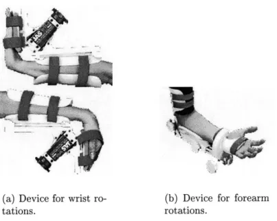
This discussion will close with a review three of the major thrusts of wrist and forearm therapy. In order to combat contracture and otherwise stiff joints, therapists will employ what is known as continuous passive motion (CPM) exercises. In these exercises, the patient's joint is forced through its range of motion a number of times. Commercial devices exist to automatically administer this type of therapy, some examples of which are seen in Figs. 2-10. The other two important types of therapy require more patient involvement. With resistance and strengthening exercises, the patient is encouraged to withstand forces and move against forces, respectively. The Multiwrist, shown in Fig. 2-11, is advertised as a portable solution to wrist exercise and assessment needs. It is configurable to provide resistance to each of the motions targeted by the wrist robot, though it is only capable of one motion at a time. Resistance is achieved by stacking weights like many universal exercise machines and the device comes with optional digital angle measurement capabilities.
(a) Device for wrist ro-tations.
(b) Device for forearm rotations.
Figure 2-10: Some commercially available CPM devices by Joint Active Systems, Inc. [59].
2.6
Implications
This chapter has covered the basic biology necessary for understanding the motivation for and execution of this project. Each topic presented here is an active area of research in its own right. It is anticipated that the completed wrist robot will not merely take its place as an advanced rehabilitative tool, but also serve as a research tool in many of these fields. Summarizing the main points to take from this discussion: " Discussion of anatomy and anthropometry helps define the proper mechanical
design constraints.
" The articular complex of the wrist can be approximated by a two-degree-of-freedom joint whose axes are perpendicular, but whose ranges of motion are coupled.
* The axis of forearm rotation is not parallel to the long bones of the arm through-out the range of motion and is referenced to a plane defined by the arm. " Knowledge of the limits of human perception should also be considered in
de-termining functional requirements for the hardware.
* Stroke can adversely affect human ability in motor control, though the brain's resiliency allows for motor recovery.
" Currently, physical therapy techniques for the wrist involve continuous passive motion, strength training, and resistance exercises, occasionally using commer-cially available mechanisms.
* Properly implemented, the device described in this thesis could provide objec-tive measurements that will benefit studies on the nature of human movement and motor recovery.
Chapter 3
System Overview
The current design of the wrist robot is the work of former Master of Science stu-dent Dustin Williams. The reader is referred to Dustin's thesis [54] as a source for understanding the thought that went into the design process. A great deal of per-spective has been gained through the re-examination of that design and experience with its hardware. This chapter presents the features of the robot and points out some of the more important differences between the original design and the present implementation. A more complete listing of the necessary modifications is provided in Appendix C. Figure 3-1 shows the robot as ultimately deployed at the Burke Rehabilitation Hospital.
Note that throughout the remainder of this thesis, the following nomenclature will be used:
PS: The motor (or corresponding axis) controlling pronation and supination, located at the back of the assembly.
ADL: The left motor (from the point of view of the patient) controlling abduction and adduction as well as flexion and extension movements.
ADR: The right motor, complementary to ADL.
Figure 3-1: Photograph of the wrist robot, currently installed at the Burke Rehabil-itation Hospital.
3.1
Functional Requirements
In laying out the framework for the design of the wrist robot, it is important to tie in the information presented in the preceding chapter. This section reviews the quantified functional requirements devised by Williams [54] and attempts to comment on their appropriateness within the context of the information presented in Chapter 2. Overall functional requirements filter down to define the specific requirements for each component of the design. The effects of these choices and the extent to which the overall requirements were met are subjects that are revisited throughout the
remainder of this thesis.
3.1.1
Ranges of Motion
The most basic requirement for this device is that it provide for motion of the wrist and forearm. Table 3.1 summarizes the stated design requirements and chosen ranges [54] for each targeted motion. The discussion from Chapter 2 suggests that the
Motion Desired Range Designed Range Wrist Flexion 700 600 Wrist Extension 650 600 Wrist Abduction 150 200 Wrist Adduction 300 300 Forearm Pronation 900 760 Forearm Supination 900 760
Table 3.1: Initial functional requirements for the robot's range of motion [54].
designed ranges would be appropriate for abduction, flexion, and extension, as they exceed the ranges expected during normal functional tasks. Wrist adduction could prove somewhat problematic, as its designed range of motion is 100 less than the maximum expected excursion in functional tasks1 . The designed ranges for pronation and supination seem useful, but recall that this value is a measure of the handle orientation in a lab reference frame and is not a measure of the patient's own forearm articulation. This situation will be discussed more fully in section 3.5.
3.1.2
Required Output Torques
Experimentation prior to the design [54] estimated that useful therapy would require 170 oz-in from the differential axes and 240 oz-in from the PS axis. It is neither expected nor desired that the robot be capable of exerting forces comparable to the maximum strengths mentioned in section 2.1. The robotic therapist's goal is to assist in patient motion; patients exhibiting hypertonicity or otherwise stiff joints may require some type of CPM treatment before using this device. The effects of spastic reflexes is not entirely known. Determination of more appropriate strength levels will be borne out through pilot studies with stroke patients.
3.1.3
Endpoint Impedance
One of the important features of MIT-MANUS is its backdrivability, a property that comes from its low mechanical impedance as seen from the endpoint. Closed-loop con-trol for this robot is accomplished using position feedback, as will be seen in Chapter 6. There is no force-feedback nor any intention to use a twice-differentiated position signal for inertia compensation. This places the onus on the designer to prevent the mechanical impedance from being dominated by endpoint inertia. Endpoint friction, which presents its own set of control problems, should also be avoided. Inertia speci-fications were qualitatively determined at 10 - 15 lb-in2 for each of the three axes in
question [54]. Frictional forces less than 30 oz-in were also deemed backdrivable [54]. Using an argument based on human perception, the most restrictive requirement on endpoint inertia occurs where the robot is acting in a "passive2" sense, so that the
reference force is the inertial load felt by the patient. This translates to an inertia requirement for the robot of 7 % of the human limb inertia of each axis. Such an exceedingly restrictive design requirement is not merely unrealistic, it is unnecessary. While part of the goal is to introduce hardware that will interact transparently with the human dynamics, feeling some inertia from the device is not prohibitive. In truth, as long as the machine is backdrivable in passive operation, the endpoint inertia is adequate. This is due to the fact that, in general, the robot will be active and the accelerations will be low, meaning the inertial load will be small in comparison to the reference force. In robot-assist mode, the inertia will likely be more difficult to notice, since the reference forces will be dominated by the actuator effort and, presumably, lower than any encountered inertial load3.
Choosing an appropriate limit for friction is an even more ambiguous task. To be-gin with, this depends on the nature of the friction considered. There are a number of different models that describe tribological phenomena. In this thesis, static, kinetic, and viscous friction will be discussed. Dry friction, encompassing static and kinetic
2
When referring to robot operation, the term passive is meant to imply that the robot has no preferred position and, therefore, is not assisting the patient toward any equilibrium point.
3
Realize that as a therapeutic device, the robot will be operate at low speed and potentially high torque. Actuator effort should influence patient motion much more than inertial loads.

![Table 2.1: Summary of key anthropometric data for the male 5 0 th percentile [54].](https://thumb-eu.123doks.com/thumbv2/123doknet/14232874.485762/28.918.222.719.121.348/table-summary-key-anthropometric-data-male-th-percentile.webp)
![Figure 2-2: Drawings from left to right: available range of motion in wrist abduction (radial deviation), a neutral position, available range of motion in wrist adduction (ulnar deviation) [31].](https://thumb-eu.123doks.com/thumbv2/123doknet/14232874.485762/29.918.193.707.627.958/drawings-available-abduction-deviation-position-available-adduction-deviation.webp)
![Figure 2-4: Drawings depicting the bone and ligament structure of the articular complex of the wrist [31].](https://thumb-eu.123doks.com/thumbv2/123doknet/14232874.485762/31.918.182.708.156.482/figure-drawings-depicting-ligament-structure-articular-complex-wrist.webp)