Characterization and Testing of a Height Adjustable Kinematic Coupling by
William R. Bosworth
SUBMITTED TO THE DEPARTMENT OF MECHANICAL ENGINEERING IN PARTIAL FULFILLMENT OF THE REQUIREMENTS FOR THE DEGREE OF
BACHELOR OF SCIENCE IN MECHANICAL ENGINEERING
AT THE
MASSACHUSETTS INSTITUTE OF TECHNOLOGY AASCt4T
June 2008
A 2008
@2008 Will Bosworth. All rights reserved.
LIBRARIS
The author hereby grants to MIT permission to reproduceand to distribute publicly paper and electronic copies of this thesis document in whole or in part
in any medium now known or hereafter created.
Signature of Author
Certified by:
Accepted by: John H. Lienhard V
Department of Mechanical Engineering May 9, 2008
Alexander H. Slocum Professor of Mechanical Engineering Thesis Supervisor
Professor of Mechanical Engineering Chairman, Undergraduate Thesis Committee
Characterization and Testing of a Height Adjustable Kinematic Coupling by
William R. Bosworth
Submitted to the Department of Mechanical Engineering on May 9, 2008 in Partial Fulfillment of the Requirements for the Degree of Bachelor of Science in
Mechanical Engineering
ABSTRACT
A new height adjustable kinematic coupling has been designed for a next generation high precision ceramics grinding machine designed to have total loop stiffness of 60 N/lIm. A test apparatus and prototype of the new coupling design has been built as the subject of this thesis to test the coupling in a model of the grinding machine layout to characterize coupling stiffness and range & precision of height adjustability. Here, the prototype coupling and test apparatus design, with initial results that verify the system's manufacturing are reported. Some design revisions to the coupling are also suggested. Future work will report coupling characterization and coupling-machine integration. Other future work will use this test setup to test and optimize control system design of the three-groove active kinematic coupling layout and finalize the component choice for the production grinding machine.
Thesis Supervisor: Alexander H. Slocum Title: Professor of Mechanical Engineering
Table of Contents
I. Introduction / Background
II. Design & Manufacture of Test Setup III. Verification / Results
IV. Future Work V. References
L Introduction
A test apparatus that resembles the size and stiffness characteristics of a new high-precision grinding machine design has been built in order to characterize a new height adjustable kinematic coupling design as well as test and optimize a control system for the stiffness and height adjustability of the new coupling. A prototype of the new kinematic coupling has been built and installed into the test apparatus and initial results have verified the manufacturing of the coupling and apparatus. This document reports the design of the coupling and test apparatus and measurement system. Future work will characterize the coupling and test and optimize the adjustable coupling's control system.
Traditionally, kinematic couplings have been passive elements[l], that is, height and preload force are chosen and set during a device's initial assembly and calibration, and scheduled recalibration. Though, some adjustable kinematic fixtures exist [2] and [3], and a kinematic coupling based active controlled 6-axis positioner has been built [4].
The coupling design presented here allows for a height adjustment and coupling preload force adjustment, which is related to coupling stiffness, to be performed by lead screw adjustments. Non-exotic motors and control systems can be installed at the lead screws to create a real-time height and stiffness adjustable coupling system.
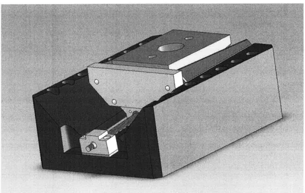
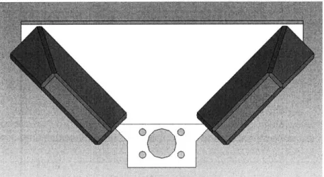
A solid model of the new coupling design is shown in figure 1 and figure 2. The lead screw shown in the figure moves the groove piece along a linear sliding bearing that is at a 5.710 incline to the horizontal. The groove-wedges have a slight taper, as shown in
figure 3, such that as the groove piece moves with respect to the ball piece, the ball piece changes height. Another approach to controlling coupling height via ball-groove adjustment is by opening and closing the groove [4], rather than adjusting its height. Details of the coupling design characterized in this thesis, with results from the test apparatus described herein are an ensuing publication.
Figure 2: height adjustable ball-groove kinematic coupling design
Figure 3: A closer look at wedge geometry in the height adjustable kinematic coupling
II. Design & Manufacture of Test Apparatus
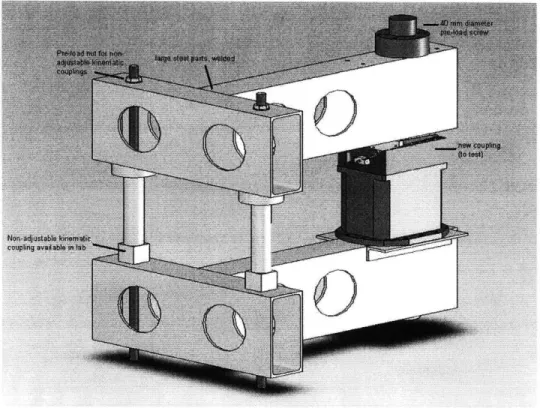
A solid model with basic component descriptions of the test apparatus is shown in
figure 4. All of the dimensional and material choices were chosen to simulate the mass and stiffness of the new wafer grinding machine that directly motivated the new
kinematic coupling design. To cut down on variables, only one height adjustable kinematic coupling is used in this apparatus; the non-adjustable couplings used in this setup are well characterized couplings from previous work in the laboratory where the apparatus was built.
Figure 4: Test apparatus solid model
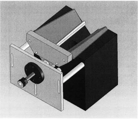
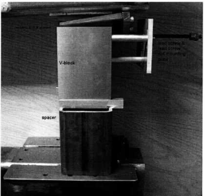
The test apparatus shown in figure 4 has the full kinematic coupling design first shown in figure 1. Due to manufacturing complications of the V-Groove Nest (see figure 2) and the desire to do statics testing without the complexity of motor control integration, a simpler prototype was built. This prototype incorporates full-scale ceramic pieces at the ball & groove point contact region of the coupling, but uses a simplified lead screw and Groove Nest. The Groove Nest is the largest low-lead-time precision machinist V-block available for purchase. This V-V-block was then machined to house the pre-loading lead screw and additional structural components for the system. A solid model of the prototype coupling is shown in figure 5 and figure 6.
Figure 5: Prototype coupling solid model, for test apparatus
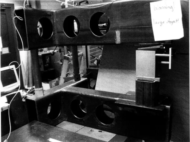
Figure 7 shows the functional test apparatus with prototype adjustable kinematic coupling. Figure 8 shows just the prototype coupling.
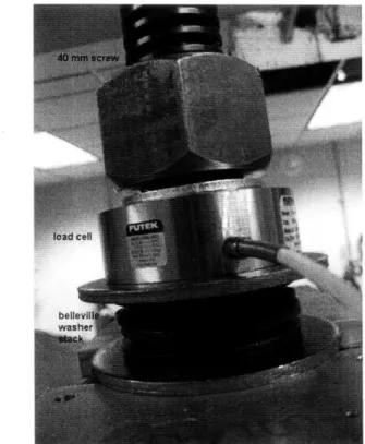
The coupling is preloaded by a 40 mm acme thread screw and monitored with a Futek LTH500 load cell that has a max load of 6.5 kN and a resolution of 8 N .To increase the resolution of force application in the screw, the preload nut is in series with a stack of Belleville washers. Figure 9 shows the coupling, preload screw, and load cell and figure 10 shows the screw, load cell, and Belleville washer stack. The nonadjustable screws also have Belleville washer stacks to increase resolution and calibrate their preload application. Figure 11 shows an installed nonadjustable kinematic coupling.
Figure 8: Built, installed prototype coupling
Figure
Figure 11: Installed non-adjustable kinematic coupling r stack
III. Verification / Results
Verification of the coupling geometry and installation have been made using digital levels with 0.1 degree resolution and dial gauges with 25 micron resolution. The results of those tests show that the ratio of horizontal to vertical displacement approaches the desired ration of 10. Load-displacement (stiffness) experimental data was taken using sub-micron resolution capacitance probes and an 8 N resolution, 65 kN capacity load cell. Results show that this coupling has a predicted stiffness of 6144 N/jtm with a standard deviation of 3578 N/jtm at 35 kN preload. The measured stiffness of the coupling, in the preload range of 5 to 6.5 kN averaged 1019 N/jim with a standard deviation of 598 N/jtm.
Ill.a. Verification of Coarse Height Adjustment
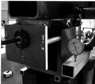
An initial verification of the coupling geometry and coarse adjustment capability was performed by turning the lead screw in increments of a half revolution of the 3 mm pitch M12 lead screw. The change in height of the test setup was measured using a 25 micron resolution dial gauge, placed in line with the vertical axis and horizontally at the location of point contact of the coupling. The rotation of the lead screw rotation was done manually and precision could be as poor as 10 degrees, which by the designed geometry of the system would lead to a height adjustment error of up to 8.2 microns per half revolution. Preload on the coupling was provided by the weight of the large test apparatus. The test setup is shown in figure 12.
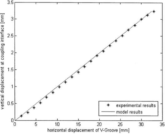
The geometry of the adjustable coupling is designed to have 1 unit of vertical displacement for every 10 units of horizontal adjustment via the lead screw. Initial tests show an average vertical displacement of 0.1472 mm for every 1.5 mm of horizontal coupling displacement. Results of vertical displacement of the test apparatus are shown in figure 13.
3r
'.i I I I I II 7*a~f..
+
---- n xperimental results nodel results 5 10 15 20 25horizontal displacement of V-Groove [mm]
30 35
Figure 13: Linear change in height with coarse adjustment in horizontal direction
No preload force was applied to the preloading lead screw during coarse adjustment measurements, because a vertical height adjustment of even tens of microns significantly alters the static load applied by the statically preload screw.
III.b Coupling Stiffness
Capacitance probes with sub-micron precision were used to measure vertical displacement at the ball-groove joint of the kinematic coupling. The coupling was loaded
by manually turning a nut on the 40 mm diameter acme-threaded lead screw. A Futek
LTH500 load cell with 65 kN capacity and 8 N resolution was used to measure the force 2.5 2 1.5 1 0.5
I
[-L ,,"F' Iapplied through the lead screw onto the coupling. Probe and load cell data were compiled using MATLAB and dSpace digital acquisition board model CP1103.
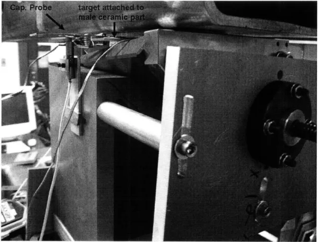
Capacitance probes measured displacement between the male ceramic piece and the V-block. A probe was placed on each side of the contact point of the ball and groove. The placement of the probes to relative to the contact point was done with a ruler, and would not have precision better than 0.25 mm. This orientation is shown in figure 14.
Figure 14: One of two capacitance probes mounted for load-deflection analysis of the adjustable kinematic coupling
In the final design, the desired preload on the coupling is between 35 to 50 kN, but in the current configuration it was impossible to apply more than 7.5 kN on the coupling. Coupling stiffness was measured using preloads between 5 and 6.5 kN, with applied loads of around 0.5 kN. It was not possible to apply predetermined loads very precisely on the lead screw (within even lkN), but logging load cell data along with displacement data allowed for compiling stiffness data post test. Figures 15 and 16 show
typical data sets created by this experimental setup: A load is applied to the screw, and displacements of the ball-groove coupling are measured. Stiffness at the given preload force is found by dividing the applied force by the coupling displacement.
initial load on coupling
fnaload on cou
\, final Ioadoqupifng -VC
1
M L,I
L,
a a w Q I I .I· ---I^-Deflection measured at Coupling
time
Load on Preload Screw
C -0 E -1 -2 5700 5600 5500 5400 5300 5200 5100
The stiffness range measured with this experimental setup is quite large, and is reported in table 1. Stiffness at the actual preload and stiffness at a preload of 35 kN, assuming the coupling follows Hooke's Law, are reported. The average predicted stiffness at 35 kN preload is 6144 N/pm, with a standard deviation of 3578 N/ptm. The relatively large stiffness range is of some concern, but will have to be rectified in future
work.
Table 1: Load-deflection analysis of adjustable kinematic coupling
Sampl Preload Load Deflection Stiffness @ Preload Predicted Stiffness @ 35
e # (N) (N) (um) (N/urn) kN (N/um)
1 6160 527 1.526 345 1960 2 5251 184 1.538 120 800 3 6270 -835 0.5 -1670 9322 4 5457 -206 0.55 -375 2405 5 5266 484 0.708 684 4546 6 6086 -820 1.04 -788 4532 7 5273 608 0.46 1322 8775 8 6365 -1150 0.9521 -1208 6643 9 5918 476 0.2441 1950 11533 10 5347 681 0.4395 1549 10139 11 6050 395 0.3296 1198 6931
Ill.d The Effect of Preload @ the Far Couplings on
It is unclear if preload on the far couplings affected the load-displacement tests performed on the adjustable kinematic coupling. Though, deflection of the adjustable kinematic coupling was observed when changing the preload at the far couplings. Figure
17 shows a data set where the left and right passive coupling elements where preloaded 1.5 turns of their respective loading screws. First one coupling was tightened, then, noted by the dotted line around the 20 second mark, the second screw was tightened the same amount, returning the coupling to level. The vertical displacement of this exercise was about 0.6 ipm, for a load of roughly 2 kN (a very rough estimate based on deflection of the Belleville washers in line with the screws) applied to each of the two couplings. Sensor ringing in figure 16 can be attributed to the application or removal of a wrench to one of the screws. Clearly, tightening the far couplings causes a displacement of the
adjustable coupling.
Deflection measured at Coupling
-1n 5880 5880 5840 5820 0" 0 0 10 20 30 40 50 time
Load on Preload Screw
,A
. .....
I I I1',,
1" 1.1 1 1 .11 1 1 1 1 1 ' IJ
1i'I
li!I '
IfII I 30 timeFigure 17: Displacement measured at adjustable coupling caused by tightening the far couplings
I I
wiJ
11
1114
1II i II i tt
H ..
YiuC
I Ii
i'
I!i II
I I Ii I LIV. Design Suggestions & Future Work
The process of manufacturing the prototype kinematic coupling leads to a few design modification suggestions. Firstly, the current ceramic ball piece has 41 mm diameter clearance hole for the 40 mm lead screw. It is suggested to increase that clearance hole to 43 or 45 mm diameter, and also include a steel insert so that the brittle ceramic part is never in danger of directly contacting the lead screw. Many tense moments have occurred when aligning the current test apparatus because of fears that the brittle ceramic piece will be chipped by the lead screw. Increasing that diameter should not affect coupling stiffness or performance.
During assembly of the prototype coupling, an error was found in the connector piece solid model. The error was simple to solve - a hole pattern that should have been a mirror of itself somehow got distorted and led to a misaligned hole pattern - but the troublesome solid model file must be updated by all of the part manufacturers involved in this project. The solid model has been fixed on the author's models.
Immediate future work will be doing more extensive testing of the load-displacement experiment to reduce the rather high standard deviation of initial results shown in this document. Extensive modeling that predicts system functionality should also be assembled.
More testing can be carried out when the Beta prototype of the adjustable kinematic coupling is manufactured, delivered, and installed at the location of the test apparatus.
Finally, control system design, optimization, and verification will be performed on this test setup once the coupling is fully characterized and accepted.
V. References
[1] Slocum, A., Design of three-groove kinematic couplings, Precision Engineering, April 1992 vol 14 no 2 pp 67-76
[2] Taylor JB, Tu JF. Precision X-Y microstage with maneuverable kinematic coupling mechanism. Precision Engineering 1996;18(2):85-94.
[3] Chui MA. Roadmap of mechanical systems design for the semiconductor
automatic test equipment industry. PhD Thesis. Massachusetts Institute of Technology; 1998.
[4] Varadarajan, K., Culpepper M. A dual-purpose positioner-fixture for precision six-axis positioning and precision fixturing Part I. Modeling and design, Precision Engineering, 31 (2007) 276-286