HAL Id: in2p3-00012345
http://hal.in2p3.fr/in2p3-00012345
Submitted on 6 Nov 2002HAL is a multi-disciplinary open access archive for the deposit and dissemination of sci-entific research documents, whether they are pub-lished or not. The documents may come from teaching and research institutions in France or abroad, or from public or private research centers.
L’archive ouverte pluridisciplinaire HAL, est destinée au dépôt et à la diffusion de documents scientifiques de niveau recherche, publiés ou non, émanant des établissements d’enseignement et de recherche français ou étrangers, des laboratoires publics ou privés.
Design Study
F. Loyer, R. Leroy, H. Safa, A. Savalle, P. Royet, F. Chautard, G. Gaubert, Y.
Huguet, B. Jacquot, P. Jardin, et al.
To cite this version:
F. Loyer, R. Leroy, H. Safa, A. Savalle, P. Royet, et al.. SPIRAL II Project (electron option) -Preliminary Design Study. [Research Report] GANIL. 2002, pp.36. �in2p3-00012345�
(electron option)
Preliminary Design Study
GANIL/SPI2/007-AFichier SPI2-007-A Preliminary Design Study.doc
TITLE
Preliminary Design Study (PDS) of the project SPIRAL II (electron option)
SUMMARY
This document presents : 1 - the objectives of the project
2 - the general principles of the radioactive ion production 3 - a technical description of the facility
4 - the radioactivity issues and the consequences on the safety 5 - a proposal of implantation on the GANIL site
6 - an estimation of the planning construction 7 - an estimation of the cost of the project
DOCUMENT PURPOSE
This document has been written, in its initial version, for : The SPIRAL II International Committee
The GANIL Scientific Council The GANIL Directory Committee
COLLABORATION
GANIL : Frédéric Chautard, Gabriel Gaubert, Yves Huguet, Bertrand Jacquot, Pascal Jardin, Nathalie Lecesne, Jean-Yves Paquet, Frédérique Pellemoine, Marie-Genevièvre Saint-Laurent, Frank Varenne
CEA/DAPNIA : Jean-Marc Baze, Aline Curtoni, Laurent Donadille, Alain Letourneau, Frédéric Marie, François Nunio, Sylvie Régnaud, Danas Ridikas, Christian Veyssière, Céline Vian
CNRS/IPNO : Olivier Bajeat, Said Essabaa, Fadi Ibrahim, Christophe Lau, François Launay, Mihail Mirea
AUTHORS
A date initial issue R.Leroy
(TISS) (target & linac)H.Safa (beam lines)A.Savalle P.Royet(safety) F.Loyer
CONTENTS
1. Objectives...4
2. Ion Production...4
2.1. PHOTOFISSION PRINCIPLE... 4
2.2. ELECTRON BEAM ENERGY... 4
2.3. ELECTRON BEAM INTENSITY... 5
2.4. RADIOACTIVE ION PRODUCTION RATE... 6
3. Technical Description of the Facility ...7
3.1. ELECTRON ACCELERATOR... 7 3.1.1. General Layout... 7 3.1.2. Gun... 7 3.1.3. Capture Cavity ... 8 3.1.4. SCRF Cavities... 8 3.1.5. Cryomodules ... 9 3.1.6. Power Coupler... 10 3.1.7. RF Source... 11 3.1.8. Low Level RF ... 11 3.1.9. Beam Transport... 11
3.1.10.Diagnostics and Control... 11
3.1.11.Cryogenic Plant... 12
3.2. ELECTRON BEAM LINE... 12
3.3. BEAM DUMP... 12
3.4. PRODUCTION TARGET... 13
3.4.1. Introduction... 13
3.4.2. Heat management... 14
3.4.3. Effusion... 14
3.5. TARGET-ION-SOURCE SYSTEM (TISS)... 15
3.6. LOW ENERGY ION BEAM LINES... 16
3.6.1. Extraction beam line and Separator ... 16
3.6.2. From pre-separator to low energy experiment area... 18
3.6.3. From pre-separator to charge breeder ... 18
3.6.4. N+ beam line from charge breeder to CIME... 18
3.7. CHARGE BREEDER... 18 3.8. IDENTIFICATION STATIONS... 19 3.9. ACCELERATION... 19
4. Radioactivity Issues ...20
4.1. GENERALITIES... 20 4.1.1. Main Rules ... 20 4.1.2. Types of radioactivity ... 20 4.1.3. Types of protection : ... 224.2. LINEAR ACCELERATOR (LINAC)... 23
4.2.1. Radiation from beam... 23
4.2.2. Activation and contamination ... 23
4.2.3. X-Rays radiation from cavities ... 23
4.3. BEAM DUMP... 24
Materials... 24
4.3.2. Radiation from beam... 24
4.3.3. Activation... 24
4.3.4. Contamination... 24
4.3.5. Incident Cases ... 24
4.4. ELECTRON BEAM LINES... 24
4.4.1. Radiation from beam... 24
4.4.2. Activation and contamination ... 24
4.4.3. Incident Cases ... 24
4.5. TARGET ION SOURCE SYSTEM... 25
4.5.2. Activation of the target... 27
4.5.3. Principle of the plug... 27
4.5.4. Activation of the materials around the target ... 27
4.5.5. Gas Contamination... 28
4.5.6. Incident Cases ... 29
4.6. SEPARATOR... 29
4.7. LOW ENERGY ION BEAM LINES AND CHARGE BREEDER... 30
4.8. CIME AND HIGH ENERGY ION BEAM LINES... 30
4.9. NUCLEAR WASTE MANAGEMENT... 30
4.9.1. Gas ... 30
4.9.2. Liquid... 31
4.9.3. Not gaseous Nuclear Wastes... 31
4.10. SUMMARY... 31
5. Facility Layout...32
5.1. CONSTRAINTS... 32
5.1.1. Radioactivity Constraints ... 32
5.1.2. Connection with the present facilities ... 32
5.1.3. Evolutions ... 32
5.2. SCHEMATIC DESCRIPTION... 32
6. Planning...34
6.1. SAFETY REGULATION ACTIONS... 34
6.2. TECHNICAL PLANNING... 34
6.3. GLOBAL PLANNING... 34
1. Objectives
This document presents a Preliminary Design Study (PDS) of the electron option of the SPIRAL II project. This PDS is based on the SPIRAL II PDS carried out in 2000 and 2001 by a working group supervised by D.Guillemaud-Mueller whose initial task was to compare technically the two following options : [1]
- fission of uranium by photons created by Bremmstrahlung from electrons accelerated up to 45 MeV by a superconducting linear accelerator (electron option)
- fission of uranium by fast neutrons (40 MeV) created by fragmentation of deuterons accelerated by a cyclotron up to 80 MeV (deuteron option)
During this study, a third option has been introduced and compared with the previous options : - fission of uranium by fast neutrons (20 MeV) created by fragmentation of deuterons accelerated by a superconducting linear accelerator up to 40 MeV, this linear accelerator being the first step of the LINAG project (LINAG I option)
The directors of GANIL, estimating that the data contained in the APS report were not sufficient to trigger a decision, required a complementary study for the electron option and for the LINAG I option.
The complementary study, carried out during the first five months of 2002, has tried to better describe the points which were technically a challenge, in particular the target design and the safety issues and to precise the plannings and the costs.
2. Ion Production
2.1. Photofission
Principle
Fission can be induced by photons exciting the Giant Dipolar Resonance (GDR) of the nucleus. This well-known process is called photofission.
The GDR cross section for 238U is shown on Figure 1 below.
0 50 100 150 200 0 5 10 15 20 25 30
Photon Energy (MeV)
σ
(mbarn)
U238 Exp U238 Theoretical fit
Figure 1 Giant Dipolar Resonance (GDR) cross section
A maximum fission probability of 160 mb is obtained for photons having energy around 15 MeV. At that energy, the photoelectric and the Compton and Rayleigh scattering cross sections are starting to fall off rapidly so the main contributions to gamma absorption are e+e- pair production and the photonuclear reactions (γ,f), (γ,n) and (γ,2n). Although the absolute fission cross section is rather small (compared to normal fission with neutrons), its contribution is not negligible as even a pair production reaction may in a thick target eventually lead to a fission through the resulting photon produced. In the same manner the neutrons produced by (γ,n) and (γ,2n) reactions as well as the (γ,f) itself can also induce fission, this time by the regular (n,f) high cross section (0.5 barn for fast neutrons). Therefore, in a thick target, photofission may be a rather interesting way of creating radioactive fission fragments.
2.2. Electron Beam Energy
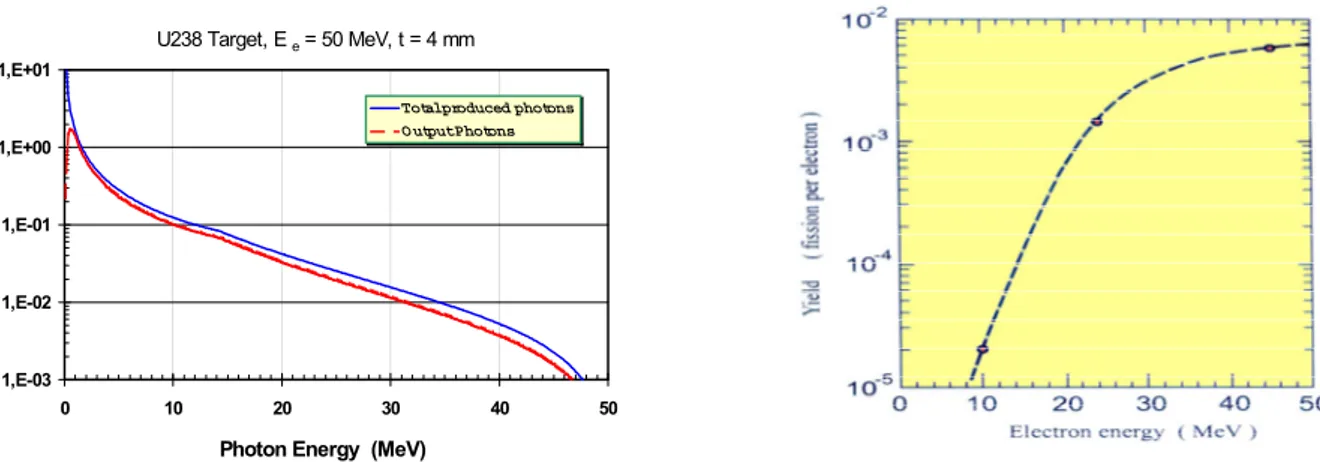
Unfortunately, no efficient monochromatic sources of 15 MeV photons are available. The most common way for producing high gamma fluxes is the Bremsstrahlung radiated by passage of electrons through matter. This process has a cross section rising linearly with energy. It will dominate the ionization process above a critical
energy (around 20 MeV). But the resulting Bremsstrahlung spectrum is widely spread in energy from zero up to the full initial electron energy (Figure 2 below). Although each single electron may ultimately produce as high as 20 photons, only a small fraction of it (0.5 to 0.7 gamma per e-) are "useful" photons lying in the GDR range (15 ± 5 MeV).
U238 Target, E e = 50 MeV, t = 4 mm
1,E-03 1,E-02 1,E-01 1,E+00 1,E+01 0 10 20 30 40 50
Photon Energy (MeV)
(Gamma / incident electron)
Total produced photons O utput Photons
Figure 2 Bremmstrahlung Yield vs photon energy Figure 3 Fission yield vs electron energy
A simple calculation including the main electron interactions (Bremsstrahlung and ionization) and the main nuclear reactions of interest (pair production and fission cross section) in a thick depleted uranium target can give the expected number of fission per incident electron. In Figure 3 above, the number of fissions produced by the (γ,f) reaction is plotted as a function of the electron energy. This result is a complete Monte Carlo calculation performed with a MCNP code offering also photonuclear capability (full electron, photon and neutron transport). The obtained result is in accordance with the simple analytic calculations.
Electron energy around 45 MeV seems a good compromise.
2.3. Electron Beam Intensity
Gamma can be produced by using a tungsten converter (4 mm thick) in front of the 238U target or by using directly the 238U target. It appears that when using a converter, less than 30% of the beam power is lost inside the converter (in contrast to the deuteron driver option). In the direct method one will produce about 25% more fission per electron (and probably more when taking in account neutron induced fission).
In order to compare photofission with and without converter, measurements of Kr and Xe isotopic distributions produced by photofission and diffused out of a thick UCx target has been performed using the PARRNe1 device in the same conditions that with deuterons beams and with the same target (see Figure 4). The measurements have been done with a 4 mm W converter in different positions (8 mm from the target, 4 mm from the target) and one measurement without W converter. Comparison with the 80 MeV deuteron induced fission measurements are also presented.
The following
Table 1 sums up the results with converter (at 4 mm in front of the target) and without converter to reach the goal of 1013 fissions/s.
for 1013 fissions/s
beam intensity beam power power inside the converter
power inside the target core
with converter 5 mA 225 kW 80 kW 6 kW
without
converter 0.5 mA 22.5 kW x 11 kW
Table 1 Comparison of the power levels between using or not using converter
As the use of a converter increases drastically the beam intensity without decreasing significantly the power inside the target, the best option is to use the target without converter.
Figure 4 Experiments carried out with the LEP preinjector (collaboration IPNO - DAPNIA - GANIL)
2.4. Radioactive Ion Production Rate
The Figure 5 below shows the radioactive ion spectrum produced by the photofission. This computation has been carried out with the code ORIHET which is an adaptation of the code ORIGEN from Oak Ridge. This spectrum does not take into account the nuclei produced by neutron induced fissions, neutrons provided by the photofission itself or by the (γ,n) and (γ,2n) reactions. These nuclei produced by neutrons represents roughly 5 % of the photofission induced nuclei and does not change the spectrum shape.
Taking into account the transmission efficiency of the various components (target, source, charge breeder, CIME) and the life time of the ions, the flux of radioactive ions provided to experiments could be the following (order of magnitude for some samples) :
Xe139 or Xe140 : 109 to 1010 ions/s Xe144 : 107 to 108 ions/s Kr89 to Kr92 : 109 to 1010 ions/s Nb100 to Nb105 : 109 to 1010 ions/s Sn132 : 108 to 109 ions/s
The lightest ions produced are around Fe (2.106 ions/s of Fe68 produced in the target) The heaviest ions produced are around Dy (2.106 ions/s of Dy171 produced in the target)
These production rates will be better estimated when all the components are designed and tested. In particular, the effusion-diffusion inside the target can change drastically the effective production at the ouput of the target for the condensable elements.
3. Technical Description of the Facility
3.1. Electron
Accelerator
3.1.1. General LayoutThe accelerator layout is shown on Figure 6 below and is quite similar to the MACSE project [2]. The injector comprises a 100 keV gun and a short cryomodule containing a single superconducting cavity. At the injector exit, the electron beam is already well relativistic. Then the beam runs in a long cryomodule through four SCRF cavities bringing the electrons to the final energy of approximately 45 MeV. A bending magnet followed by a transport beam line will get the beam at the right place and shape onto the target.
Injector
Injector
collimator collimatorβ
β
=1
=1
Cryomodule
Cryomodule
beambeam dump dump
analysis analysis target target beam beam dump dump transport transport line line deviation deviation 100keV
100keV 5MeV5MeV 45MeV45MeV
4 SCRF
4 SCRF cavities cavities
e-e-gungun capture SCcapture SC cavity cavity
12 m
Figure 6 Layout of the electron driver 3.1.2. Gun
The gun uses a standard thermoionic cathode sited on a 100 kV platform. The power supply can deliver up to 3 mA in current. In order to bunch the beam at the proper frequency of 1.5 GHz, a specific line consisting of two rectangular RF cavities (chopper) are used to cut a 60° phase out of the DC beam delivered from the cathode. Another cylindrical cavity (buncher) is used to bunch the beam down to a 10° phase at the entrance of the capture cavity.
An attractive alternative method would be to set up a gridded cathode similar to the one used in Inductive Output Tubes (IOT). In that way, the beam could be bunched right from the starting emission point that suppresses the need of the rather cumbersome bunching line. This new technique could be tested at CEA/Saclay and if successful, will be implemented on the SPIRAL II machine.
A collimator can be placed after the gun in order to control the beam emittance. This could be of importance for safety and radiation issues (see § 4.2.1) as undesired beam tails can be quite easily suppressed at that stage without creating too much radiation.
3.1.3. Capture Cavity
The capture cavity is a superconducting cavity with a reduced beta value due to the not fully relativistic beam coming out from the gun. Geometry has to be optimized to properly capture the beam without degrading too much the longitudinal emittance. Figure 7 below shows some simulations where different cavity shapes have been studied. 0 1 2 3 4 5 0.1 0.2 0.3 0.4 0.5 0.6 0.7 0.8 z (m) energy (MeV) β=1 cav hybrid cav β=0.85 cav @Bpk=50mT 0 1 2 3 4 5 6 7 8 -180 -150 -120 -90 -60 -30 0 30 60 90 120 150 180 phase z=0 (deg) energy (MeV) hybrid cav β=0.85 cav β=1 cav @Bpk=80mT
Figure 7 Output energy as a function of position and phase for three different cavity shapes. A β = 1 cavity is
clearly not adequate to use as a capture cavity.
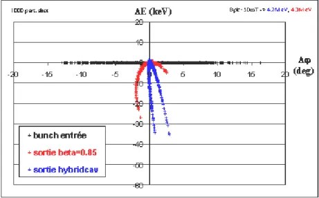
The output dispersion of the beam shown on Figure 8 below is simulated for two different cavity shapes assuming an input beam with 200 eV and 30° extension in phase. It can be noticed that the output beam will feature less than 40 keV and 5° in the longitudinal phase space.
Figure 8 Longitudinal dispersion at the output of the capture cavity for two different shapes 3.1.4. SCRF Cavities
The four SCRF cavities are standard β=1 elliptical cavities working at the resonance frequency of 1.5 GHz. The characteristics of these cavities are summarized in Table 2. The important thing to point out is the high accelerating field operation (19 MV/m) and the very low bandwidth (40 Hz) due to the low beam current.
The cavity will use an integrated helium tank vessel and a specific tuner will have to be developed. A great care should be taken as regard to the low bandwidth. Therefore, any improvement made on tuners developed in the frame of the CEA/Saclay-IPN/Orsay collaboration for SCRF cavities could be implemented in SPIRAL II. For example, the use of piezoelectric tuners if demonstrated would be of great benefit.
SPIRAL II SCRF CAVITY
Frequency 1 500 MHz Beam Power 4,756 kW
β 1,000 Dissipated Power 9,058 W
λ 0,200 m Incident Power 4,767 kW
(β∗λ/2) 0,100 m Incident Q 3,80E+07
(r/Q)/cell 50 Ω Zero Current Voltage 1,90E+07 V
Slope X 1,90E+10 Ω
Number of cells 5 V 9,52E+06 V
Bpeak 80 (mT)
Bpk / Eacc 4,2
Eacc 19,05 (MV/m)
Q0 2,00E+10 All External Q's 1,00E+11
Length 0,500 m Loaded QL 3,79E+07
(R/Q) 250 Ω Bandwidth (2.∆f) 40 Hz
Stored Energy 19,222 J
α inc
0,997724α cavity
0,001897Maximum Voltage 9,52E+06 V
α ext
0,000379Beam Current 5,00E-04 A
Phase 2,000 degrees Reflected Power 1,72E-04 W
Actual Voltage 9,51E+06 V Cavity Losses 9,058 W
Energy Gain 9,512 MeV Transmitted Power 1,812 W
Detuning Angle -1,992 degrees Cavity Frequency 1 500,000 MHz
Frequency Shift -0,69 Hz
Table 2 Typical SCRF cavity characteristics. 3.1.5. Cryomodules
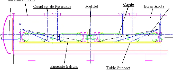
Two separate cryomodules are needed. The first will house the single capture cavity and the second one the four SCRF β=1 cavities. These cryomodules are similar to the one used on the MACSE test bed but will be modified to take into account the fact that the helium vessel is suppressed, each cavity having an individual helium tank. Schematic drawings of the largest cryomodule are shown in Figure 9 and Figure 10.
The assembly of cavities and couplers has to be done inside a class 100 clean room in order to avoid dust contamination. The assembly can be done outside the clean room provided the cavity/coupler ensemble is leak tight and sealed. The insertion in the cryomodule of the full 4-cavity assembly has to be done from the side.
Figure 10 Front view of the cryomodule. The cavity is laid on a cooled table in a cradle shape structure on the bottom side of the helium vessel.
3.1.6. Power Coupler
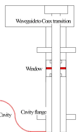
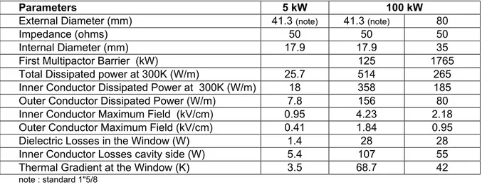
The power coupler is an important (and weak) element bringing the RF power from room temperature down to the cold cavity. It should be stressed that even though the power level is rather low (5 kW), this item should be developed and fully tested during the TDS phase. If not, the overall schedule would shift as the power coupler is on the critical path. Moreover, in view of a future upgrade, it would be very interesting to check whether the power coupler could be designed to withstand a CW power of 100 kW. Some basic parameters for the two options (5 kW & 100 kW) are described in Table 3. Basically the external diameter should be higher for the high power operation to avoid the multipacting bands. The mechanical impact on the cryomodule mounting has also to be thoroughly analyzed. The TDS work should determine if a high power coupler could be safely implemented at that stage or not.
Figure 11 Schematic design of the coaxial coupler for SPIRAL II.
Waveguideto Coax transition
Window
Parameters 5 kW 100 kW
External Diameter (mm) 41.3 (note) 41.3 (note) 80
Impedance (ohms) 50 50 50
Internal Diameter (mm) 17.9 17.9 35
First Multipactor Barrier (kW) 125 1765
Total Dissipated power at 300K (W/m) 25.7 514 265
Inner Conductor Dissipated Power at 300K (W/m) 18 358 185
Outer Conductor Dissipated Power (W/m) 7.8 156 80
Inner Conductor Maximum Field (kV/cm) 0.95 4.23 2.18
Outer Conductor Maximum Field (kV/cm) 0.41 1.84 0.95
Dielectric Losses in the Window (W) 1.4 28 28
Inner Conductor Losses cavity side (W) 5.4 107 55
Thermal Gradient at the Window (K) 3.5 68.7 42
note : standard 1"5/8
Table 3 Coaxial power coupler parameters for both the 5 kW and 100 kW options 3.1.7. RF Source
The RF power is a 5 kW CW klystron TH2466 from Thalès (formerly Thomson) company. A complete RF power source includes :
• The klystron tube (5 kW CW) • A power supply (11 kV, 1.2 A)
• A waveguide WR650 circulator (5 kW any phase) • A water power load WR650 (5 kW CW)
• Miscellaneous waveguide components, couplers, elbows, transitions, etc…
The RF tube could be installed right close to the cryomodule minimizing the length of waveguides and reducing the RF losses.
3.1.8. Low Level RF
SCRF cavities have to be regulated in frequency, field amplitude and phase. A precise regulation is required to maintain the cavity at the right frequency and the accelerating field at the right value and phase. The frequency is controlled using the cavity tuning system to better than 1 Hz. It is generally a rather low speed (typically one second) when using the stepping motor. A high gain feedback loop for cavity phase and amplitude is necessary to compensate for mechanical vibration and microphonics. It should be possible to obtain with a properly designed phase lock loop a field control better than 1% and a phase control better than 0.1 degree. Each cavity has to be driven by a single RF power source. This is very important to guarantee the phase and amplitude control.
3.1.9. Beam Transport
The beam transport is rather simple taking in account the fact that a 45 MeV electron beam is highly relativistic (γ ∼ 90). In particular, no specific focusing is required inside the cryomodules. An intermediate analysis line could be useful in between the two cryomodules (at an energy of 5 MeV) in order to fully characterize the beam at the exit of the capture cavity.
3.1.10. Diagnostics and Control
The diagnostics required for the driver are of two types. The first type is mainly for operation to check whether the parameters are properly set as expected and do not change with time. That includes beam current monitors, beam position monitors, beam profile measurements (during commissioning) and all current
measurement of the magnetic elements. For the cavities, the RF signals will be measured (input, reflected and transmitted fields) together with frequency (phase), amplitude and error signals. Cavity vibrations could also be measured using a piezoelectric device on the tuner mechanism. X-ray signal in case of field emission could be monitored using simple diodes. Of course, all cryogenic diagnostics like helium pressure, temperature and mass flow will also be measured on line, in addition to vacuum measurements, especially on sensitive locations like the gun or the cryogenic insulation vacuum.
The second type of diagnostics will be used for interlocks in case of severe failure leading to beam
interruption. First, for safety reasons, beam losses should be maintained below a given value. Therefore, they should be continuously measured online using for example a calibrated differential current monitor at the beam exit. Then, all possible failure scenarios for each element (gun, cavity, cryogenics, RF power source, RF
scenario is for example a vacuum leak in the cryostat insulation. Mitigation in this case would include a specific device added (as a rupture disk) at a calibrated pressure (2 bars) and a corresponding beam interlock.
3.1.11. Cryogenic Plant
The required cryogenic power is of the order of 150 W at the working temperature of 1.9 K including the static losses, the power coupler losses and a standard margin. The Hélial 2000 liquefier from Air Liquide can fulfill these requirements. Using nitrogen pre-cooling, its performance can reach 130 l/h in the liquefying mode and over 400 W (@ 4.5 K) in the refrigeration mode. This liquefier has many interesting characteristics as the static gas bearing expansion turbines and the industrial oil lubricated screw compressor. It offers the remote monitoring from a distant location (control room) through a fully automated controller.
Although the liquefier is the major component of the cryogenic plant, the overall plant should include the liquefier (150 W @ 1.9 K), a large dewar, a helium compressor, a storage tank for helium gas, a pumping station, transfer lines for helium and nitrogen, a liquid nitrogen reservoir and all ancillary components : controller, gas purification, heater, etc…
3.2. Electron Beam Line
The electron beam is sent horizontally upon the target. Because of the beam energy stability which is estimated to 2 %, a doubly achromatic deviation is thought useful so that the instabilities on target are avoided. Two 90° bending dipoles and 7 quadrupoles are needed (see on Figure 13 below).
The magnetic rigidity being small (0.15 T.m..), the size of the magnetic elements are small too. For instance, the size of dipôles could be 500x500x300 mm3 and their weight about 300 kg.
According to the target size and shape, the beam spot can be moved using a pair of deviating magnets. This easily allows covering any area shape on the target. For example, an annular beam can be formed using only 0.05 T deviating magnets in the (xy) planes and located 2.5 m away from the target.
The tuning of the linac will be caried out by sending the full intensity beam on a beam dump (see § 3.3)
Beam dump To target N°2 quadrupole x-y deviator target N°1 Figure 12 Beam Dump Principle
Figure 13 Electron Beam Line Principle
3.3. Beam
Dump
The full intensity beam can hit the beam dump, which means that the 22.5 kW power of the beam must be evacuated. The core must be cone-shaped and the beam defocused to spread the beam power (see principle on Figure 12 above)
Moreover, the materials must be chosen to reduce as more as possible the activation and the outside radiation (see § 4.3.1)
3.4. Production
Target
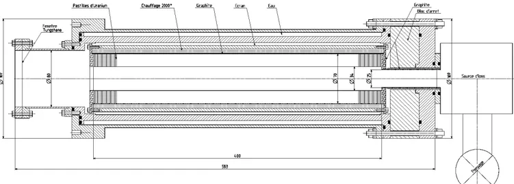
3.4.1. IntroductionThe target material is based on the use of depleted uranium. In order to release efficiently by diffusion in the solid matrix the fission products, the target has to be heated to the highest possible working temperature (around 2000°C). Therefore, a ceramic compound of uranium able to withstand that temperature without degradation has to be selected like for example uranium carbide. But the carbide has many thermodynamic phases depending on temperature and composition. Moreover, the metallurgical form is also of importance as for example the open porosity or the small grain size which are proved to be better for the diffusion process. As a consequence, a full and proper characterization of the material target (fabrication process, density, porosity, phase composition and proportion, thermal properties like thermal conductivity at 2000°C, emissivity, etc…) is thoroughly needed as it may strongly impact the target design. It is important to notice that the optimal target for photofission should clearly be somewhat different from the usual ISOL type target used until now with neutron beams all around the world.
One important issue for the target is its thermal capability. Due to the fact that a significant fraction of the beam power will be deposited inside the target, a proper management of the heat transfer inside the target is needed. Therefore, an annular target geometry has been selected for the two main following reasons : - it allows a much better heat transfer to the outer wall and a better flatness of the radial temperature
distribution inside the target,
- it offers the great possibility of taking out very rapidly the short lived radioactive fission products by an effective effusion through the wide open central area.
Therefore the target geometry will look like a long hollow cylindrical shape containing a stacking of several uranium carbide washers. Consequently, the incoming beam has to be shaped accordingly to the target cross section. But the annular shape required is quite easy to deliver with a relativistic electron beam, as any shape, even quite cubersome, could be painted on the target using a set of different magnetic coils and quads. As a matter of fact, in § 3.2, a very simple arrangement using a set of deviating magnets 90° out of phase, is proposed to establish the desired beam profile on the annular target.
The technology to produce these thin uranium carbide disks has to be demonstrated in the Preliminary Design phase. The present technology commonly used either at IPN Orsay (Parrne) or at CERN (ISOLDE) enables to fabricate (by cold pressing of a mixture of uranium oxide and graphite powders) disks of 14 mm in diameter and about 1 mm thickness. Larger diameters could eventually be achieved with the same technology but it is unlikely that much thinner material could be fabricated using the same process. Therefore, a different technology is proposed to obtain the required uranium carbide disks geometry. Based on already commercially available 0.125 mm shaped graphite washers, the fabrication process will use a thin uranium layer deposition followed by an adequate heat treatment. This new technology is presently under investigation at CEA Saclay.
As a result, an example of a target design that could be used for a photofission target is shown on Figure 14
3.4.2. Heat management
A complete calculation of the temperature profile inside the target has to be done in order to assess its thermal capability. Therefore, even though the total deposited heat is only about 50% of the beam power, the target has been designed to withstand the full power beam heating (22.5 kW). The final temperature will be achieved by adding some external heat power through a heater installed quite close (or even bounded) to the target container.
First in the radial direction, the deposited heat by the beam is transported through the matrix to the outer container wall (mostly by conduction, but also due to the high working temperature, the radiation transfer has also been taken into account). A contact resistance between each disk and the container has been assumed. From the container to the outer cooling, channel, the heat transfer is done mainly by radiation. Therefore, a screen has to be added in between the cooling outer shell (containing the water flow) and the target container (where the temperature has to be maintained at 2000°C). It is important to notice that our heat problem is neither a regular target type (where the heat has to be evacuated very efficiently), nor an oven type (where the insulation has to be very effective to maintain a high temperature at low flux). Here, both the deposited heat and the temperature are fixed. So, the heat problem has quite well constrained boundary conditions. A first order simple calculation give the radial temperature profile in the center of the target. This profile is confirmed using complete 3-D calculation (based on CASTEM code) and shows that a temperature of 2000°C can be readily achieved in the target even using a full power beam deposition (20 kW). In those calculations, an average thermal conductivity of 20 W/m.K has been assumed for the uranium carbide.
There are two possible ways of achieving the most uniform temperature longitudinal profile. Uniformity is desired for two reasons : avoiding the hot spots that may induce local overheating and even damage and avoiding the cold spots where the fission products can have longer sticking time. The first way is to design the target to spread out the interaction all along the beam path. This can be done either by shaping the disk profile and/or the beam or by changing the disk composition. The second way is to compensate the underheating of the second half part of the target by adding a separate heater. Of course, both ways could be simultaneously implemented to finally achieve a quite uniform smoothening of the deposited heat all along the z axis. Of course, a special care has to be taken for the end parts as they will also be affected by radiation especially on the back side.
Champ de température final
VAL - ISO > 6.77E+01 < 2.06E+03 83. 1.77E+02 2.70E+02 3.64E+02 1.58E+03 1.67E+03 1.77E+03 1.86E+03 1.95E+03 2.05E+03
Evolution de la temperature sur f(r)
ABS T 0.00 1.00 2.00 3.00 4.00 5.00 6.00 X1.E-2 0.00 0.50 1.00 1.50 2.00 2.50 X1.E3 P 11 P 12P 21 P 22 P 31 P 32 P 41 P 42 P 51 P 52
UC
x RESISTANCEECRAN
BÂCHE
Source Faisceau sur UCxSource sur Résistance
Figure 15 Temperature profile along the radial direction 3.4.3. Effusion
Once the diffusion process has brought the atom up to the surface and expelled it in the vacuum, the heavy atom has to travel to the output opening by bouncing on the different surfaces. The fly path is done with an average velocity corresponding to the Maxwellian distribution at the operating temperature. Depending on the atom, each collision with a surface will result in a sticking residence time corresponding to the bonding energy during the adsorption phase (for example, the sticking time of a rare gas element is extremely small – a few µs, whereas the sticking time of some refractory elements can be very large – seconds or more due to chemisorption). This is called the "effusion" process. The average path length and the number of wall collisions can be calculated for a given geometry by Monte-Carlo techniques.
It turns out that there is an optimum value for the ratio of disk thickness (=a) to the spacing (=d) between two disks. If the disks are too close to each other (d/a small), the atoms will bounce indefinitely between the disks,
hardly getting in the open central area. Whereas, if the disks are too far from each other (d/a large), the overall length of the target and hence the fly path will be too long. As can be seen from Figure 16, the optimum value for (d/a) is around 0.75.
A quite important feature is resulting from the effusion calculation. As stated earlier, this target geometry is very favorable for the effusion of short lived elements. Due to the large central hole, a non negligible fraction of the short lived fission products can be collected in the ion source. In fact, some atoms (a few percent) can even cross the whole target without any collision. A histogram distribution of the number of collisions is shown in Figure 17. The total effusion time can be calculated by adding the flight pass time to the total sticking time. As an example for tin, the flight path time is of the order of 10 ms, while the total average sticking time is 90 ms for a single sticking time of 0.2 ms. It is important to note that, depending on the surface composition and condition, the single sticking time may vary with several orders of magnitudes (from 10-8 s to 10-1s for Sn). The collision probability, as can be expected, follows an exponential decrease, the highest value being at zero collision. We believe this is a very important added value for this project.
0 5 000 10 000 0.0 0.5 1.0 1.5 2.0 2.5 3.0
(d/a)
Number of collisions
Minimum obtained for (d/a) = 0.75 Number of collisions = 1000
Figure 16 The number of collision variation with the ratio of disk spacing to thickness (d/a).
Figure 17 Histogram of number of collisions for a 10000 particle Monte-Carlo
3.5. Target-Ion-Source System (TISS)
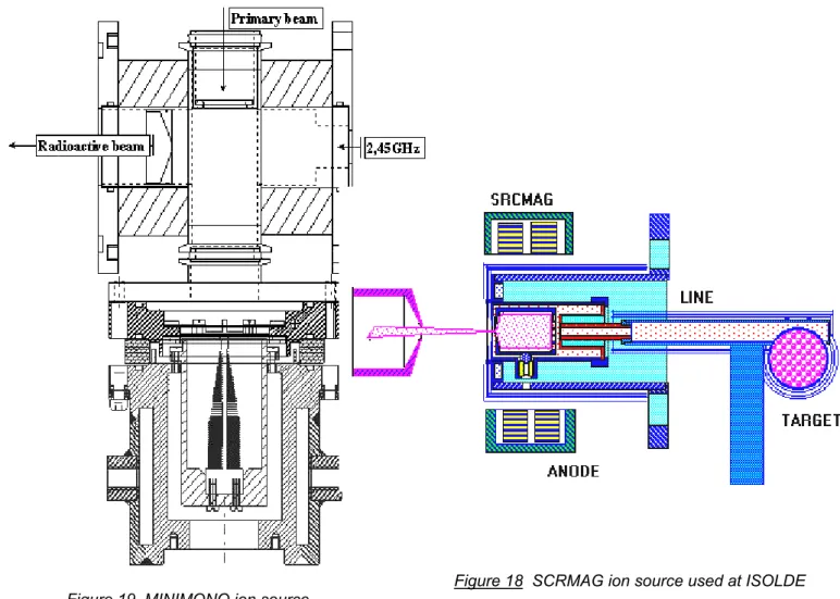
The ionization source will be installed in a module described below, as close as possible to the target. The chemical features of the radioactive element to produce will define the type of the ionization source regarding its efficiency. The main methods considered are surface ionisation for alkali elements, an electron cyclotron resonance ion source for noble gases or for volatile mono-atomic or molecular elements, and a laser ion source for refractory elements. Correspondingly existing sources for radioactive ion production are respectively described in the references [4, 5, 6]. These sources (an exemple is given on Figure 18 with the SCRMAG ion source used at ISOLDE) can be implemented inside the plug that implies an angle of 90° between the primary beam and the axis of the separator.
However the field of production is always under developments and new sources are under studies keeping in mind that the design of the target and ion source system should, particularly, take into account the parameters having an effect on the global efficiency; i.e. the diffusion of the radioactive atoms out of the target, their effusion up to the source and the ionisation efficiency. Different experiments and developments were carried out at GANIL concerning the target-source system of SPIRAL. The experience acquired in these works and the know-how for the conceptions of such production systems are of paramount importance in achieving good design and performances.
Original works are underway in numerous laboratories like TRIUMF, GANIL or ISOLDE to maximise the efficiency of the target source system specially dedicated to gases. A new inexpensive fully permanent magnet 2,45 GHz ECRIS, called MINIMONO (see Figure 19), has been developed at GANIL and will be tested at ISOLDE. A new version of this ion source with coils (with better radiation hardness) is presently under development. Special radiation resistant coils will be tested soon in a different ECRIS at TRIUMF. The combination of the technological developments at GANIL and the know-how of TRIUMF and ISOLDE will allow increasing significantly the production efficiency of radioactive ions with high reliability.
It will be possible to install any one of the proposed sources in the production module, the ECRIS being the biggest one. In all cases, the lifetime to be considered for the production system is 3 months. The replacement of the whole production system will be performed in a hot cell, specially designed for such an operation.
Figure 18 SCRMAG ion source used at ISOLDE Figure 19 MINIMONO ion source
connected to the present SPIRAL target
3.6. Low energy Ion Beam Lines
3.6.1. Extraction beam line and SeparatorThe ion source associated to the target system will produce 1+ ions. The beam emittance depends on the kind of the ion sources which will be used. It may be from 10 π.mm.mrad with the surface ionisation sources for alkaline atoms to 100 π.mm.mrad with the ECR sources for the noble gas. New smaller ECR sources under development (MONO1000 or MINIMONO) could provide lower emittance (30 π.mm.mrad) The extraction optics will be calculated, if possible, for the maximal emittance expected.
The extraction optics, located in a high activation level environment, has to be simple. The number of diagnostics elements and, consequently, of optics elements, should be minimized.
A large number of elements are produced in the target-source system. According to the experiment requirement, several masses may be selected by a mass pre-separator.
The mass separator may be a magnetic dipole or a Wien filter. The advantage of the last one is that the mass used at low energy may be chosen almost independently of the mass post-accelerated. Yet, a dipole is easier, particularly to put in a high activation environment. Its curve radius could be 500 mm.
One mass will be driven to a charge breeder, for post-acceleration, while one (or two) other(s), in the range of +/-15 % (or +/-20 %) from the central mass, will be sent to low-energy experimental area(s). The lateral beam(s) may be deflected with an electrostatic deflector, which is movable parallel to the focal plane of the pre-separator to select the ion mass, and to drive it back to the right trajectory. This scheme is inspired by GPS at ISOLDE whom Figure 20 below shows the electrostatic part. [7]
Note that this mass separator is not a precision spectrometer. The resolution will be about 1/100. The separation will be finalized in CIME, or with a high precision spectrometer for the low energy experiments.
Figure 20 ISOLDE Separator Principle : movable electrostatic deflectors behind the dipole
The optics elements before the dipole have to be electrostatic, to drive all masses up to the pre-separator. A quadrupole triplet is one solution.
dipole Electrostatic quadrupoles deflector 1+ source charge breeder To low energy physics magnetic quadrupoles dipole dipole
3.6.2. From pre-separator to low energy experiment area
A simple beam line will conduct the low energy beam to experimental areas. The equipment used at LIRAT (in construction) might be used both by SPIRAL I and SPIRAL II
In addition, it may be useful to build a spectrometer dedicated to low-energy physics. A 1/2000 mass resolution may be reached with a dispersion of 4 meters and a beam width at object point of +/- 0.5 mm, with an emittance of 10 to 30 π.mm.mrad.
3.6.3. From pre-separator to charge breeder
The 1+ beam has to be matched before entering the n+ source, to ensure a good efficiency. A second dipole (the first one is the separator) may be used to obtain a doubly achromatic beam, so that the tuning does not depend on the presence of impurities. The beam line is described on Figure 21.
3.6.4. N+ beam line from charge breeder to CIME
The N+ beam line is described on Figure 22 below. It is thought, apart some details, as a symmetry of the SPIRAL I injection beam line (from source to matching point). The identification bench will be 45 degrees rotated to serve both for SPIRAL and SPIRALII. The 45 degrees dipole D52 has to be changed into a double-entrance dipole.
solenoid
Identification bench
CIME injection line
SPIRAL I
ICD52
charge breeder
Figure 22 Schematic Ion Beam Line between the Charge Breeder and CIME
3.7. Charge
Breeder
The goal of the 1+/n+ transformation consists in increasing the charge state of the singly charged incoming ion to a charge state compatible with the acceleration by the CIME cyclotron or by the C0. For the heaviest elements like 144Xe, that means a 36+ charge state to reach Q/A= 0.25 that corresponds to an energy of arround 15 MeV/A after acceleration.
It’s obvious that the efficiency of the 1+ to the n+ ion production and the charge breeding time are fondamental parameters in this method for radioactive ions.
An ECR booster has been developped by the SSI group at ISN Grenoble (France) based on the use of a Phoenix ion source at 14 GHz. The present results with this source are summarized in
Table 4 below :
Charge Breeding Efficiency on
the most abundant charge state Overall Efficiency
Noble gas 10% 50 to 70%
Condensable elements 6% 45%
Table 4 Order of magnitude of charge breeding characteristics with stable elements.
The most abundant charge state can be shifted to higher values by using higher UHF frequency.
In that way, an upgrade of the source is going on by increasing the radial magnetic field until 1.6 T and the plasma volume. The UHF frequency will be 18 GHz.
Other solutions like the use of superconducting ion sources (SERSE or GYROSERSE) for example could be studied in the future.
3.8. Identification
Stations
Two identification stations are proposed : one between the 1+ source and the charge breeder and the other one at the output of CIME, after the charge breeder.
They allow to :
- control the production of the target via the 1+ source and the separator - control the good behaviour of the charge breeder
- control the identity of the ions injected into CIME.
The present identification station used for SPIRAL can be used also for SPIRAL II
3.9. Acceleration
GANIL presents several possibilities of post-acceleration :
a - CIME can deliver a beam energy from 7 to 10 MeV/n with charge provided by a charge breeder designed with the top-end ECR source technology. (Figure 23 below).
Max Ion Energy with CIME
5 6 7 8 9 10 50 70 90 110 130 150 ion mass energy (MeV/u) 142Xe 23+ 132S n 22+ 73Kr17+ 105Nb 19+
Figure 23 Maximum Energy at the output of CIME
b - CSS2 coupled to CIME can accelerate the same ions between 11 and 21 MeV/n, with a stripping between them. The maximum energy could reach 39 MeV.A, but with a degrade of the possibilities of C0-CSS1-CSS2 (modification of injection radius of CSS1 and extraction radius of CSS2). This solution is not recommended. c - the ions going out the 1+ source can be accelerated by C02, CSS1 and CSS2 and the energy at output of SSC2 would range from 35 to 50 MeV.A.
This beam line could be constructed underground, partly inside the power supplies building. A long straight line (80 meters) could be constructed as in the PIAFE project. Then the line would have to turn left, up to a charge breeder. Afterwards, a beam line would drive the beam up and inject it into the C02. The two beam lines before and after the charge breeder are similar to IC line of SPIRAL and the total length is about 40 m.
These last option has been precisely studied in the frame of the LINAG-1 project [8]
d - a specific booster can be designed to accelerate the ions after CIME or instead CIME. These options are out of the frame of this project but the implantation of the facility will try to keep free the room needed for such a booster.
4. Radioactivity Issues
4.1. Generalities
4.1.1. Main RulesThe main rules to respect concerning the radioactivity issues are :
- the ALARA (As Low As Reasonnably Achievable) approach which advises (imposes?) to reduce as low as possible (technically and economically) the radiation dose received by people.
- the thresholds of radiation or contamination : not regulated
zones surveillées""zones "zones contrôlées" radiation dose < 2.5 µSv/h < 7.5 µSv/h > 7,5 µSv/h
α emitters contamination <8 mBq/m3 < 25 mBq/m3 > 25 mBq/m3 βγ emitters contamination < 3.5 Bq/m3 < 10 Bq/m3 > 10 Bq/m3 The not regulated zones are all the zones outside the building
The "zone surveillées" are the technical galleries where category B people can work permanently
The "zones contrôlées" are the caves being able to receive the beam or having a high level of radiation and whose access is regulated
- the release of nuclear waste to atmosphere (gas) or to used water network (liquid) must respect the authorizations of release
4.1.2. Types of radioactivity
The types of radioactivity which must be dealed with are: - the radiation induced by the beam impact onto the matter :
*gamma photons induced by electrons (Bremsstrahlung) : their energy spectrum and their intensity depends on the angle emission and on the type of materials. This type of radioactivity occurs along the electron beam line where the beam can be lost or fully stopped (the beam dump and the target). The maximum flux is obtained when the full beam is stopped. It can reach 3.1016 MeV/s if the electron beam is stopped in heavy metal (copper or iron).
*neutrons induced by photofission ((γ,f) reactions) : These neutrons are created in the target where uranium photofission occurs. The production yield is around 3.4 n/fission. The total flux is therefore about 3.1013 n/s. The flux is roughly isotropic and the energy spectrum can reach 20 MeV for an averrage energy of 4 MeV. The energetic flux is therefore around 1014 MeV/s.
*neutrons induced directly by gamma photons ((γ,n) and (γ,2n) reactions). These neutrons are created everywhere gamma photons go through matter, in particular in the beam dump and in the concrete around the beam dump. They exist also in the target and induce complementary fissions. Such a flux inside the target is roughly equivalent to the fission induced neutron flux.
*neutrons induced by energetic ions : When their energy is higher than the Coulomb barrier, the ions can create nuclear reactions which induce a flux of neutrons. That can occur only inside CIME and along the high energy beam lines. The consequent radiation is already taken into account in SPIRAL facility.
These radiations stop as soon as the beam stops.
X-Rays radiation from linac cavities due to electron emission. This radiation stops when the cavities are turned off.
- the activation of the matter , consequences of the nuclear reactions :
*fission of uranium by gamma photons inside the target creates two fragments per fission. Most of them are radioactive (it is the goal of the project) and their desintegration emits both β -radiation which induce gamma photons by Bremmstrahlung and gamma photons by desexcitation. The global activity is shown in Figure 24 below. It reaches 1500 Ci after 15 days of irradiation. Taking an average decay energy of 2 MeV, the global gamma radiation energy is 1014 MeV/s. Although, by the principle of the target, a part of these radionuclei go out of the target but, for radioprotection issue, all the radionuclei are considered staying inside the target.
*fission of uranium by neutrons (neutrons from (γ,n) or (γ,2n) reactions and from
photofission). The global production of fission products by this way reaches 80 Ci after 15 days of irradiation (5 % of the photofission products) which must be added to the photofission products.
*transuranic elements produced by neutron capture. From codes CINDER and DARWIN, the activity of alpha emitters is around 2 mCi after 15 days of irradiation and is roughly constant after several years of cooling. 99 % of this activity is due to Uranium (238 +235) used in the target. The main artificial element is Pu239 which is responsible of 99.9 % of the artificial activity. Among the artificial elements, a very small activity is provided by Radon. It seems (to be checked
precisely) this activity is lower than 1 Bq just after the irradiation and reaches almost 50 Bq after several years of transuranic element decay. If these results are confirmed, the problem of the radon release has not to be taken into account.
*nuclear reactions induced by neutrons : the neutrons created by photofission or directly by the gamma photons induced nuclear reactions in the matter. In particular, all the matters (cupper, tungsten, concrete, cooling water) put down around the radiation sources (beam dump, target and others) will be made radioactive. The air inside the caves can also be activated. This matter activation will have to be taken into account and the materials will have to be chosen to minimize it.
The radiations induced by matter activation are permanent and decrease according to the life time of the radionuclei initially created and of the radionuclei coming from their desintegration. In particular, the activity of the target decreases according to the law shows on Figure 24 above.
- the contamination by radioactive materials (dust, gas, aerosol) which are carried and deposited. This contamination is mainly coming from the fission products which go out the target.
The Figure 25 below describes the main routes followed by the fission products (parents only) according to their physical state. One of the problem to take into account is the fact the radioactive nuclei can break up into another nuclei whose the physical state is different. For instance, a solid can be desintegrated into a gas (Sb gives Te which gives Iodine which gives Xenon).
The intensities mentionned on Figure 25 are the highest ones which can be got. In particular, the intensity at the output of the separator (1011 ions/s) is for a gaseous element (Kr or Xe) selected by the separator, element whose transmission efficiency is assumed 100 % between the target and the source output.
4.1.3. Types of protection : - Protection of workers against radiation
The goal of the protection is to keep the radiation dose received by the workers as low as possible and, in any case, lower than the threshold acceptable for the classification of the place.
As it is difficult to reduce the source level (it is sometimes possible by reducing the beam intensity for instance), the only means are to put down shielding between the source and the workers.
Normal concrete (d=2.4) or heavy concrete (d=3.2) will be the basic shielding.
Sometimes, an association of different materials can be interesting (metal plus concrete).
Figure 26 below gives two examples of transmission : Bremmstrahlung gammas (20 MeV in averrage) and fission neutrons (4 MeV : high part of the spectrum).
condensable at 2000°C (ex : Mo) not condensable at 2000°C condensable at room temperature gas at room temperature under vacuum (P vapour > qqs mbar) (ex : Iode)
PUMPS
SOURCE 1+
TARGET SEPARATOR DIPOLE
effusion 30keV 30keV 30keV
T T
SOURCE N+
30keV CIME
Atm.
gas at room temperature (P vapour > 1 bar) (ex : Xe, Kr)
DISPERSAL OF FISSION PRODUCTS (parents) ACCORDING TO THEIR PHYSICAL STATE
T
T gas diffused after a certain delay condensable at room temperature pulled out by beam sputtering after a certain delay 2.1013 ions/s 1013 ions/s 1013 ions/s 2.1012 ions/s 1011 ions/s 5.1012 ions/s T 5.1010 ions/s 5.1010 ions/s 5.1011 ions/s (Xe, Kr)
4 MeV neutron transmission 1E-12 1E-10 1E-08 1E-06 0,0001 0,01 1 0 1 2 3 4 concrete thickness (m) tr ansm is si
on normal concreteheavy concrete
20 MeV photon transmission (without "build-up") 1E-12 1E-10 1E-08 1E-06 0,0001 0,01 1 0 2 4 6 shielding thickness (m) tr ansm issi on normal concrete heavy concrete lead
Figure 26 Transmission of gammas and neutrons in shielding
- Protection of workers against contamination
The goal is to avoid that workers swallow or breathe radioactive matter. The best solution is to reduce as much as possible contamination inside the rooms, therefore to keep the fission products and their descendants in containers (vacuum chambers, gas bottles) without leakage outside, except by the way of the authorized means of release. One of the problems is these ions can change their states (a solid can give a gas like iodine ions which decay into xenon ions)
Protection of environment
The release of nuclear waste will have to respect the authorizations in any cases. In order to keep a safety margin sufficient to include the consequences of accidents, the release in normal conditions of working will have to stay at least two orders below the authorization level.
The next paragraphs deal with the radioactivity issues for each major part of the facility : linear accelerator, electron beam line and its beam dump, target ion source system (TISS), source extraction beam line, separator, low energy radioactive beam line and its main components (identification bench, charge breeder, dipoles), CIME
4.2. Linear Accelerator (Linac)
4.2.1. Radiation from beamIn a superconducting electron linac, a beam loss never occurs inside the RF cavities. However, it seems impossible to demonstrate this fact because the codes used to simulate the electron dynamics consider that the components are without defects. Also, the maximal beam loss taken into account for the radioprotection is the one which can be detected. The accuracy of the instrumentation allows to measure a beam loss of 1 % with reliability. This electron beam loss induces an energy flux of 1015 MeV/s. The Bremmstrahlung yield in copper or iron (about 0.4) induces a gamma flux of 3.1014 MeV/s with a mean energy of 20 MeV. The radiation, at 1 m, is 2.4.109 MeV/cm2/s if we assume the radiation is isotropic.The dose equivalent at 1 m is therefore 2.4.107 µSv/h (the conversion coefficient is 0.01 µSv/h/MeV/cm2/s for 20 MeV gamma). To reach 7.5 µSv/h behind the shielding (at 3 m), its thickness, around the linac, must be about 2.5 m if it makes of normal concrete or 1.5 m of heavy concrete.
4.2.2. Activation and contamination
As the beam losses will be very small in practice and as the activation induced by 45 MeV electrons is very low (only secondary neutrons can activate a little), the activation and, therefore, the contamination of the linac should be negligible.
4.2.3. X-Rays radiation from cavities
The X-Rays appear when internal electron emissions occur inside the RF cavities. These electrons, accelerated by the RF field, induce photons exactly as the electron beam itself. The cavity RF field chosen to reach 45 MeV should not induce X-Rays. However, X-Rays detectors check permanently the X-Rays level and the RF field will be adjusted to keep compatible with the shielding.
4.3. Beam
Dump
4.3.1. MaterialsThe full intensity beam can hit the beam dump. The electrons can transfer their energy by ionisation, excitation and Bremmstrahlung. To reduce the gamma radiation created by Bremmstrahlung, the material which stops the beam must be light. The best material is the carbon because there is no production of long life time radioactive ions and a very low neutron production.
To stop the gammas which can go out the carbon block, a shielding in heavy material can be added around the dump. Iron is good candidate because its activation by neutrons is low (only short life-time nuclei are created)
The beam dump used at ELBE facility [3] is a good example (Figure 27)
Figure 27 Beam Bump designed for the project ELBE 4.3.2. Radiation from beam
The Bremmstrahlung yield in carbon is 0.1. The gamma flux is therefore 1016 MeV/s. A similar calculation as for the linac shows the dose equivalent reaches 109 µSv/h at 1 m (if isotropic). The iron shielding reduces the radiation by a factor 103 roughly. 2 m of concrete (1 m of heavy concrete) could be sufficient to reduce the dose equivalent down to 7.5 µSv/h. Similar calculation will be to carry out around the beam dump, taking into account the energy of the gammas are lower.
4.3.3. Activation
The activation of the materials of the beam dump (carbon, iron, copper) and of the shielding (concrete) by the neutrons is to be calculated.
4.3.4. Contamination
The contamination will be confine inside the beam dump chamber. 4.3.5. Incident Cases
The major incident could be the loss of cooling without stopping the beam.
The container where the beam dump is installed will design to catch the melted matters.
4.4. Electron Beam Lines
4.4.1. Radiation from beam
The beam loss should be negligible. In case of failure of guidance elements, the beam loss will be detected either directly (measurement of the beam transmission) or by the means of the induced radiation and the beam stops.
4.4.2. Activation and contamination
The activation and, therefore, the contamination of the beam line components (vacuum chamber) should be negligible.
4.4.3. Incident Cases
The major incident could be the boring of the vacuum chamber by the beam. The pressure elevation in the chamber triggs security actions.
4.5. Target Ion Source System
4.5.1. Radiation during irradiationAs shown on Figure 28 below, the radiation going out the target (included the source) consists of : - electrons (1015 MeV/s) from the electron beam
- gammas (1016 MeV/s)from : Bremmstrahlung of electron beam decay of fission products
Bremmstrahlung of β- radiation
This radiation induces a flux of 1011 MeV/cm2/s at 1 m (if isotropic) and a dose equivalent of 109 µSv/h. - neutrons (1014 MeV/s) from : (γ,n) and (γ,2n) reactions
fission reactions
This radiation induces a flux of 5.108 n/cm2/s at 1 m (mean neutron energy of 2 MeV) and a dose equivalent of 3.107 µSv/h.
With the target design as presented in § 3.4, the spectra of these radiation are shown Figure 29, Figure 30 and Figure 31.
The shielding is designed by taking into account the most energetic radiation, therefore the gamma radiation. 3.5 m of normal concrete or 2 m of heavy concrete is sufficient around the target to allow the permanent
presence of workers behind the shielding during the irradiation. A further shielding made of heavy metal (lead, tungsten or, better for activation issues, iron) around the target can reduce drastically the concrete thickness needed.
e-γ
PF
n
γ
γ
β−
γ
PF
TU
α
n
γ
e-PF
2.1015 e-/s 45 MeV => 1017 MeV/s 1016 MeV/s 1015 MeV/s 1014 MeV/s ENERGETIC BALANCE SHEETINSIDE THE TARGET (during irradiation) 9.1016 MeV/s 1013 MeV/s
PF
pumping 5.1012 MeV/s separator target + sourceγ
TU
2.1013 PF/s electron beamNeutron Spectra out of Target
1,E-06 1,E-05 1,E-04 1,E-03 1,E-02 1,E-01 0 5 10 15 20Neutron Energy (MeV)
Number of Neutrons per Incident Electron per MeV
Backwards Lateral Forward Total
Figure 29 Neutron Spectra out of the target
Electron Spectra out of Target
1,E-05 1,E-04 1,E-03 1,E-02 1,E-01 0 10 20 30 40 50
Electron Energy (MeV)
Number of Electrons per Incident Electron per MeV
Backwards Lateral Forward Total
Figure 30 Electron Spectra out of the target Photon Spectra out of Target
1.E-06 1.E-05 1.E-04 1.E-03 1.E-02 1.E-01 1.E+00 0 10 20 30 40 50
Pho ton Energ y (MeV)
N u m b e r of P hot on s pe r I n c ide nt E le c tro n pe r M e V Backw ards Lateral Forw ard Total
4.5.2. Activation of the target
After the irradiation stops, the only cause of radiation is the decay of the fission products. To simplify, we assume that all the fission products stay inside the target.
The graphs Figure 24 show the activity versus time during irradiation and the decay of the activity after the end of irradiation. After 15 days of irradiation, the activity is roughly 1500 Ci, that corresponds to 1014 MeV/s of beta radiation if we assume that the mean decay energy is 2 MeV. The gamma radiation is 1013 MeV/s if we assume that mean Bremmstrahlung coefficient is 0.1. At 1 m, the radiation flux is therefore 108 MeV/cm2/s (if isotropic) and the dose equivalent 2.106 µSv/h. The shielding adapted to the irradiation period (109 µSv/h) is sufficient to protect workers against this level of radiation.
If the target is stored after waiting for one day of cooling, the activation is only 150 Ci with a dose equivalent of 2.105 µSv/h and the shielding needed is roughly 1 m of concrete or less according to the internal shielding of the target (see § 4.5.1 above)
4.5.3. Principle of the plug
The dose rate due to gamma radiation just after the stop of the primary beam is estimated to attain 2 Sv/h at 1 m from the target after 15 days of irradiation (see § 4.5.2 above). One day after, the radiation rate is still 200 mSv/h. This high level of radiation does not permit manual intervention on the target itself. Thus the different operation must be studied with this constraint in mind.
The target and the ion source will be placed in a rectangular module (called plug) that is surrounded by 2 m of concrete for shielding of workers and equipment. The same principle has been applied on the ISAC facility at TRIUMF (Vancouver, Canada), for the production of radioactive beams with a 500 MeV, 100 A primary beam. At this time, two solutions are under studies : the first one consists in sending the primary beam vertically while the second one prefers to send it horizontally. These two solutions will be studied in details during the next months and a final approach will be taken considering the advantages and the disadvantages of each one. Two turbo molecular pumps and the insulators are thereby located on the top of the plug where they are protected from radiations. This increases the life time of the different components and permits the manual disconnection of the electrical powers.
The 2 m thickness of concrete reduces the dose rate on the top of the plug down to 7.5 Sv/h when the beam is stopped that allows people to come and work on the equipments located at this place.
The target ion source system is immersed in the vacuum created by the two turbo molecular pumps located on the plug. The plug can be closed at the entrance and at the exit by two plates moved with air piston. The plug itself is contained in a large vacuum tank with concrete packed tightly arround to minimize air activation. This tank contains three modules. Module 1 contains the target ion source system and the
radioactive nuclear beam extraction electrodes. Module 2 contains electrode, profile monitors, slits and beam profile to monitor, transport and adjust beam characteristics of the RNB from the ion source to the mass separator. Module 3 contains the magnetic dipole, the energy slits and the electrostatic defletors (see § 4.6 below)The vacuum connections between the modules do not need seals as the plug is immersed in vacuum.
After irradiation, the different connections of the plug (electrical connections, primary pumping, water connections,…) can be manually removed. The plug is then remotly removed from the production cave and is evacuated to a storage cell. Depending on the state of the target ion source system, the plug can be re-used or moved to a hot cell where the elements at the bottom of the module can be replaced with master/slave
manipulators.
A dedicated handling system will be studied for the manipulation of the plugs taking into account the different risks induced by this action. In particular, the risk of fall involving a risk of dispersion of contamination will be carefully studied.
However, the handling system will permit to remove the plug and to put it again into the tank to be re-used or to bring it up to the shileded cell to be dismountled.
4.5.4. Activation of the materials around the target
As already said, the air activation is reduced to its minimum as the plug and the TISS are immersed in vacuum. Nevertheless, the small volume of air surrounding the target tanks will be considered as the same level as the hot cell inner volume and the building is zoned to ensure that the air movement is directed to these volumes. The air of each room surrounding the hot cell and target tanks is sampled and monitored.
The problem of the water activation has been studied in ISAC facility and the same system will be installed. It consists in a closed loop passing through a heat exchanger. The water of the primary circuit is drained to a buffer volume where it can be monitored prior to release to the outside drains.
All the materials around the target (concrete in particular) will be irradiated and activated by neutrons. However, this activation will be more a problem of nuclear waste than a problem of radioprotection. The calculation of this activation will have to be carried out in the frame of the nuclear waste management.