HAL Id: cea-02509245
https://hal-cea.archives-ouvertes.fr/cea-02509245
Submitted on 16 Mar 2020
HAL is a multi-disciplinary open access
archive for the deposit and dissemination of
sci-entific research documents, whether they are
pub-lished or not. The documents may come from
teaching and research institutions in France or
abroad, or from public or private research centers.
L’archive ouverte pluridisciplinaire HAL, est
destinée au dépôt et à la diffusion de documents
scientifiques de niveau recherche, publiés ou non,
émanant des établissements d’enseignement et de
recherche français ou étrangers, des laboratoires
publics ou privés.
Reactor
M. Guyot, P. Gubernatis
To cite this version:
M. Guyot, P. Gubernatis. Toward an improved methodology to simulate the initiating phase of a
severe accident in a Sodium Fast Reactor. ICAPP 2015 - International Congress on Advances in
Nuclear Power Plants, May 2015, Nice, France. �cea-02509245�
Toward an improved methodology to simulate the initiating phase of a
severe accident in a Sodium Fast Reactor
M. Guyot1 and P. Gubernatis2
1CEA (Alternative Energies and Atomic Energy Commission), DEN, DTN, SMTA, LPMA Building 219
Tel: +4 42 25 31 73, Email:maxime.guyot@cea.fr
2CEA (Alternative Energies and Atomic Energy Commission), DEN, DTN, SMTA, LPMA Building 219
Tel: +4 42 25 66 36, Email:pierre.gubernatis@cea.fr
Abstract – To consolidate the safety assessment for Sodium Fast Reactors, hypothetical core
disruptive accident sequences have been extensively studied over the past decades. These sequences are initiated by a very low probability coincidence of an accident precursor, such as the stop of primary and/or secondary pumps, and failure of one or more safety systems. Regarding Sodium Fast Reactor systems, a major concern is that the core, at nominal, is not necessarily in its neutronically most reactive condition. From the computational point of view, a severe accident scenario is generally broken down into subphases as the initiating phase, the transition phase, the expansion phase and the decay heat-removal phase for applying specific code to each phase. The present research project is dedicated to the analysis and the quantification of bias corresponding to the computational methodology employed to simulate the initiating phase of severe accidents on Sodium Fast Reactors. To evaluate these biases, an extension of existing modeling capabilities is required. To fulfill these needs, a new computational model has been developed. This new model is based on a multi-physics coupling and makes use of modern parallel computing architectures. The computational model has been applied to obtain new information in regards to neutronics and thermal-hydraulics models and their coupling.
I. INTRODUCTION
A key research goal of Sodium Fast Reactors (SFR) is an enhanced safety compared to former nuclear reactor concepts (i.e. GEN-II systems and former SFR designs) and thus safety requirements at least identical to GEN-III standards are required. To a large extent the safety considerations will dictate the SFR design characteristics and play a major role in establishing the economic attractiveness of this concept. In particular, the treatment of low probability events leading to core disruption, also called Hypothetical Core Disruptive Accidents (HCDA), is one of the key issues of R&D plans for the advanced reactor systems in general, and for SFR in particular. These sequences are initiated by a very low probability coincidence of an accident precursor, such as the stop of primary and/or secondary pumps, and failure of one or more safety systems. Regarding SFR systems, a major concern is that the core, at nominal, is not necessarily in its neutronically most reactive state.
From the computational point of view, a severe accident scenario is generally broken down into subphases
as the initiating phase (IP), the transition phase, the core-material relocation phase and the decay heat-removal phase for applying specific code to each phase. During the IP, the subassembly wrapper tubes keep their mechanical integrity. Material disruption and dispersal is primarily one-dimensional. For this reason, evaluation methodology for the IP relies on a multiple-channel approach. Typically a channel represents an average pin in a subassembly or a group of similar subassemblies. In the multiple-channel approach, the thermal-hydraulics model of the core is composed of parallel 1 or 2 D channels. The thermal-hydraulics model is coupled to a neutronics module to provide an estimate of the reactor power level. The simulation of the IP of such accidents is of particular interest both for the prevention and the mitigation of routes leading to a large core disruption and recriticalities.
A deterministic approach is carried out to assess the consequences of a severe accident by adopting best estimate design evaluations. An objective of this deterministic approach is to provide guidance to mitigate severe accident developments and recriticalities through the implementation of adequate design measures. These
studies are generally based on modern simulation techniques to test and verify a given design. Reference codes for analyzing severe accidents on SFRs have been developed several decades ago. Due to the dramatic increase of computing resources, it is now highly desirable to improve the accuracy and the predicting capabilities of computational tools. In particular, the physics of severe accident involves complex phenomena associated to very fine time and length scales which are connected to different fields such as neutronics, hydraulics and thermal-mechanics.
The present research project is dedicated to the analysis and the quantification of bias corresponding to the current computational methodology for simulating the IP of severe accidents on SFRs. To evaluate these biases, an extension of existing modeling capabilities is required. To fulfill these needs, a new computational model has been developed. This new model is based on a multi-physics coupling and makes use of modern parallel computing architectures. The computational model has been applied to obtain information unavailable up to now in regards to neutronics and thermal-hydraulics models and their coupling. Because the severe accident phenomenology is intricate and involves numerous physical models, the logic pursued in our approach is to proceed by a sensitivity approach to evaluate the relevance of a given model and to provide relative trends rather than trying to produce best-estimate results. Based on these analyses, a new methodology has been produced to improve the safety assessment of SFRs by decreasing the bias related to the deterministic analysis of severe accident scenarios.
The present paper is a review of the research activities conducted recently at the Laboratory for Severe Accident Modeling (CEA Cadarache) concerning the development of a new computational route for severe accident on SFRs. In the remainder, code development and results are compiled and discussed. Some of these results have been presented in separate previous publications1,2,3,4,5. The
paper is structured as follows. First, we describe the standard computational route used to simulate a severe accident and discuss the reasons for developing a new approach. Then, a description of the new computer model is provided. Finally, numerical results and perspectives are discussed.
II. COMPUTATIONAL ROUTES FOR SEVERE ACCIDENT
II.A. Standard computational route
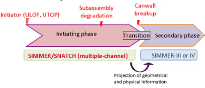
The standard computational route for severe accident scenarios is depicted in Figure 1 along with the most widely used codes:
Figure 1: Standard computational route for severe accident
To analyze severe accidents resulting from under cooling or overpower situations, the SAS4A/SASSYS-1 computer code has been developed at Argonne National Laboratory for the safety assessment of SFRs6. The
SAS4A/SASSYS-1 code is designed to perform deterministic analysis of the IP of HCDA in SFRs and is currently used worldwide for the safety analysis of SFRs. The subassembly wrapper breakup indicates the onset of a transition phase, which is calculated by the SIMMER-III or IV code7. The core state and geometry are transferred from
SAS4A/SASSYS-1 to SIMMER to continue the severe accident analysis. SIMMER is dedicated to the analysis of molten pool and recriticalities.
While many aspects of the SAS4A/SASSYS-1 and SIMMER codes have been validated against experimental data, several limitations have been identified concerning the standard computational route, as for example:
- The neutron kinetics capability: SAS4A/SASSYS-1 is based on a point kinetics (PK) model which neglects the power shape variation. Neutron diffusion and transport theory capabilities have been added to the SAS4A/SASSYS-1 code for the analysis of thermal reactors14 and accelerator driven systems
but no application to SFRs has been performed up to now.
- The subassembly thermal-hydraulics model: SASA4/SASSYS-1 resorts to a simplified treatment in which an average pin is used to represent a subassembly or a group of similar subassemblies. While an assembly subchannel model has been integrated in the SAS4A/SASSYS-1 computer code for use with the pre-boiling models, this model has not been extended yet to the coolant boiling and the fuel/cladding relocation models.
- The transition to subsequent phases of degradation: The current computational route involves a transfer of SAS4A/SASSYS-1 data to the SIMMER-III (or IV) code. Difficulties arise when applying this scheme, because of inconsistencies between SAS4A/SASSYS-1 and
SIMMER models (thermal-hydraulics closure laws, neutronics model …).
II.B Alternate computational route
To evaluate the bias related to the standard computational route, an alternate computational route has been developed (see Figure 2). The two-dimensional fluid-dynamics SIMMER-III code7 has been coupled to the
three-dimensional SNATCH neutron transport solver8 to
produce a new code which is used as a replacement for the SAS4A/SASSYS-1 code. This coupling allows both to compute the multi-phase and multi-component flows encountered under severe accident conditions and to model the power shape variation during voiding and melting of the different reactor materials. Accordingly, the main benefits from this coupling are:
- A multiple-pin representation of the fuel subassembly (SIMMER-III is a two-dimensional axisymmetric fluid-dynamics solver).
- A space-time kinetics model (high-order transport capability).
- The same code (SIMMER) is applied for IP and transition phase.
Figure 2 : Alternate computational route for severe accident
III. COMPUTER MODEL
In the present section, a description of the multiple-channel SIMMER-III/SNATCH code is given. A brief outline of each code capability (i.e. SIMMER-III and SNATCH) is firstly provided. We also describe the coupling scheme and its implementation. Then, emphasize is put on the new features introduced by adding the space-time kinetics model to a multiple-channel code. In particular, a new level of time scale has been incorporated to implement the spatial calculation of the flux shape.
III.A. The SIMMER-III code
The SIMMER-III code is an advanced safety analysis computer code designed to investigate postulated HCDA in SFRs. SIMMER-III is a two-dimensional multi-velocity-field, multi-phase, multi-component, Eulerian fluid-dynamics code coupled with a fuel-pin model and a space-
and energy-dependent neutron kinetics model7. For this
reason, the SIMMER-III code is well-adapted for simulating multi-dimensional and multi-phase phenomena occurring during the IP of a core disruptive accident, such as sodium boiling, fuel and cladding melting and freezing and fuel-coolant interaction.
III.B. The SNATCH code
The SNATCH solver is a three-dimensional high-order discrete ordinates solver for the neutron transport equation. This solver has been recently implemented in the ERANOS code system9. SNATCH has the ability to model
core geometries based on hexagonal assemblies. A three-lozenge-based discretization of the hexagon is used. A space-time kinetics model has been included in the SNATCH transport solver10,11. The so-called quasi-static
scheme, which relies on a flux factorization into a time-dependent amplitude function and a space-and-time-dependent shape function, has been implemented to assess the behavior of a reactor core during accidental conditions. The quasi-static approach consists of a two-level nested iterative procedure, in which the shape equations are solved over a coarse time scale ∆t while the amplitude equations are solved over a fine time scale δt. To be computationally efficient, this method requires a ratio ∆t/δt as large as possible.
Perturbation tools consistent for the SNATCH solver have also been developed in order to compute first-order derivatives or exact decomposition of a given quantity of interest with respect to some system parameters. In the framework of coupled reactor physics and thermal-hydraulics computations, perturbation theory is used to compute coolant, fuel and cladding reactivity coefficients and Doppler reactivity coefficients.
In addition to its space-time capability, the SNATCH code includes a PK and reactivity feedback model for use together with a multiple-channel description of the core geometry.
III.C. The multiple-channel coupled computer code
A parallel processing coupling approach is utilized to couple the SNATCH kinetics model with the SIMMER-III code. The scheme is based on a SAS-like multiple-channel approach6. In this context, the core is described in terms of
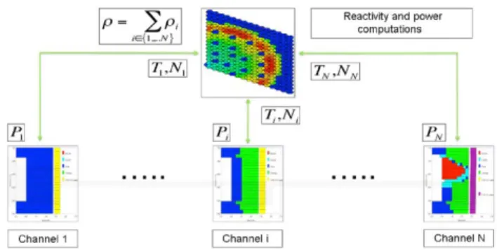
several 1 or 2D thermal-hydraulics channels; each channel being computed separately by a SIMMER-III run. Neutronically, a single SNATCH computation is performed to model the core behavior. This coupling is schematically depicted in Figure 3. At the bottom, thermal-hydraulics channels are represented and interact with the neutronics module (at the top of Figure 3).
Figure 3 : Data exchange topology for the SIMMER-III/SNATCH coupled code
To insure a high computational efficiency, this code is built with the hybrid model of parallel programming using both distributed programming and shared memory multiprocessing programming technics. In this approach, the codes run separately and exchange data during a calculation. The data exchange is performed using a Message Passing Interface (MPI) environment at given rendezvous (RDV) instants. To benefit from the multiple-channel approximation, the different thermal-hydraulics channels are computed on different processors corresponding to different SIMMER-III executions. In this way, the wall clock time required for a full-core calculation is drastically reduced. In addition to the parallelization of the reactor into channels, an implementation of multithreading is present both in SIMMER-III and SNATCH. This hybrid model of parallel programming enables to increase the scalability of the coupled calculations while keeping reasonable computing time.
The coupling scheme imposes the exchange of a certain amount of data at certain RDV times. To implement the neutronics/thermal-hydraulics coupling, the following information is sent from each SIMMER-III process to SNATCH:
- Axial distribution of density for coolant, fuel and cladding (denoted by Ni in Figure 3)
- Axial distribution of temperature for coolant, fuel and cladding (denoted by Ti in Figure 3)
These values are then used to compute the reactivity and power distribution over each time step. Conversely, the end-of-time-step power distributions (Pi)i=1..N are sent back
to the different channels which corresponds to the different SIMMER-III runs. The SNATCH process (represented at the top in Figure 3) acts as a master process of the algorithm and performs all neutronics-related operations such as reactivity and power computations. There is no interaction among the SIMMER-III processes.
To obtain the nominal state of a reactor with the multiple-channel SIMMER-III/SNATCH code, a special
iterative procedure has been developed. This iterative scheme is detailed in Figure 4.
Figure 4: Strategy for obtaining the nominal state of a reactor
The temporal scheme relies on successive critical calculations to obtain the steady-state neutron flux as depicted in Figure 4. The flux is then normalized to calculate the nominal power distribution. At each time step 𝑡𝑡𝑖𝑖𝑠𝑠ℎ𝑎𝑎𝑎𝑎𝑎𝑎, information is transferred between the neutronics model and the thermal-hydraulics model of the core based on the data exchange topology detailed on Figure 3. Because SIMMER-III is a transient code, the thermal-hydraulics state of the core is advanced in time to obtain the new reactor state for each time step 𝑡𝑡𝑖𝑖𝑠𝑠ℎ𝑎𝑎𝑎𝑎𝑎𝑎. The time step should be large enough to allow the temperature distribution to be stabilized. When a stable state is obtained, a new critical calculation is performed with updated cross sections and the thermal-hydraulics channels are advanced to the next time step. The convergence of such a procedure can be observed both on neutronics and thermal-hydraulics quantities.
For a transient calculation, the procedure detailed in Figure 4 is also applied except that the neutron transport equation is solved for a transient problem in this case (and not for a critical problem).
Coupled three-dimensional neutron kinetics and thermal-hydraulics computations are performed with three different levels of nested time scale. The different levels are depicted in Figure 5. Shape time step is the outermost time step level. This time step is used to perform the three-dimensional flux computation. It is divided into several RDV time steps; a RDV time step being discretized into PK time steps. A thorough description of the two innermost loops has been provided in Ref. [3]. For each RDV time step, a time discretization of each SIMMER-III fluid-dynamics channel is also carried out. The time step size of each channel is automatically limited so that the fluid-dynamics time step coincides with the RDV time steps.
Figure 5: Time-step hierarchy
IV. NUMERICAL ANALYSIS
IV.A. Treatment of core-wide coherency effects
During the IP, the subassembly wrapper tubes keep their mechanical integrity. Material dispersal is primarily one-dimensional. For this reason, evaluation methodology for the IP relies on a multiple-channel approach where a channel represents an average pin in a subassembly or a group of similar subassemblies. For simulating the accident sequence, a subassembly-to-channel assignment procedure has to be implemented. A subassembly-to-channel assignment procedure intends to account for the non-synchronicity of phenomena between the multiple channels. The channel lumping can be produced by imposing a range of variation over relevant reactor parameters such as power-to-flow ratio, distribution profile of reactivity coefficients, burnup... Subassemblies sharing reactor parameters in the same interval are gathered together and merged as channels.
The multiple-assembly-per-channel approach introduces core-wide coherency effects which can affect the reactivity balance and therefore the overall accident development. To evaluate these effects, a sensitivity analysis has been conducted2. In this approach, a severe
accident has been simulated by assuming a complete loss of forced flow in the primary system of the reactor along with the failure of the reactor shutdown system. Such a scenario is often referred to as an Unprotected-Loss-Of-Flow (ULOF). Its selection for analysis is based on the fact that this accident illustrates a situation where non-coherent phenomenon might be expected to occur throughout the entire reactor core.
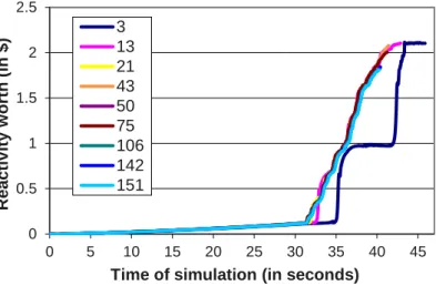
To evaluate core-wide coherency effects, the number of channels has been varied and a one-subassembly-per-channel reference case has been computed for comparison. The core selected for this analysis is a large SFR core featuring a positive void effect due to sodium removal. For the selected core with 453 subassemblies arranged in one-third symmetry, a complete description requires 151 channels (reference case). Some results are shown in Figure 6 and Figure 7.
In Figure 6, the change in the coolant feedback reactivity slopes indicates the time of sodium boiling inception for the different cases. We see that this time decreases when the level of incoherency in the core representation increases. This feature is the consequence of steady-state variations due to the core homogenization.
A 3-channel case has been calculated. As expected, the 3-channel case presents the steepest coolant voiding reactivity ramp due to the important core-wide coherency added by the modeling of the core (see Figure 6). In this case, coolant voiding contribution of one channel amounts to a 0.9$ reactivity insertion. This leads to an important amount of positive reactivity insertion due to cladding dispersal. As a consequence, prompt criticality is reached in this case.
Figure 6: Coolant feedback reactivity versus time
It has been found that a too coarse representation of the core leads to substantial differences in the overall accident development, while a refined subassembly-to-channel arrangement increases the accuracy of the calculation. In our case, a refined channel arrangement yields milder accident consequences.
From the results, we also observe that the number of channels employed in the simulation should be increased if cladding and fuel dispersal occurs during the transient. In this case, coherency effects are higher because cladding and fuel dispersal reactivity insertion are stronger than sodium voiding reactivity insertion.
Absolute deviations of the averaged fuel-melting fraction with respect to the one-subassembly-per-channel calculation are shown in Figure 7. Results in Figure 7 are assessed at the onset of the transition phase and provide a good illustration of the sequence convergence while refining the channel arrangement. Results for the 106-
0 0.5 1 1.5 2 2.5 0 5 10 15 20 25 30 35 40 45 R e a c ti v ity w o rth (i n $ )
Time of simulation (in seconds) 3 13 21 43 50 75 106 142 151
3-channel arrangement 13-channel arrangement
21-channel arrangement 50-channel arrangement
106-channel arrangement 142-channel arrangement
Figure 7: Absolute deviations of the averaged fuel-melt fraction with respect to the reference calculation
channel case proved to be in very good agreement with the reference 151-channel case. The deviation is inferior to 1% for the pointwise fuel-melt fraction between the two cases (see Figure 7). This choice provides the same level of accuracy as a one-subassembly-per-channel choice with a 30% reduction of the overall computing time. These results are useful to save both computing time and memory storage.
IV.B. Multiple-pin representation of the fuel bundle
Numerical simulations of the IP of HCDA are currently performed with the SAS4A/SASSYS-1 code6.
The SAS4A/SASSYS-1 severe accident calculation scheme resorts to a simplified treatment in which an average pin is used to represent a channel. This approach suffers from the lack of a subchannel representation (i.e. a radial description of the fuel bundle) and thus neglects two-dimensional effects. While an assembly subchannel model has been integrated in the SAS4A/SASSYS-1 computer code for use with the pre-boiling models, this model has not been extended yet to the coolant boiling and the fuel/cladding relocation models and thus applications of the assembly subchannel model are limited to small-scale design-basis accident situations12, 13.
To assess the bias related to subassembly lumping into a single-pin, the comparison between single-pin and multiple-pin models has been conducted using the SIMMER-III/SNATCH coupled code on a full-core ULOF scenario3. The SIMMER-III fluid dynamics model is a 2D
cylindrical model that encompasses mass, energy and momentum exchanges between neighboring radial channels. Radial mass, energy and momentum exchanges are treated in the same way as for axial transfers by the SIMMER-III fluid dynamics model during all the accident phases (i.e. even in the presence of a multi-phase, multicomponent flow).
Two models for the subassembly representation have been considered (see Figure 8). The single-pin configuration considers a single average pin representing the subassembly (one radial mesh) and the multiple-pin configuration models the 10 rows of fuel pins (10 radial meshes) in 2D axisymmetric fashion. Each row of fuel pin is cylindrical and includes the quantity of fissile material and steel corresponding to the number of fuel pins in the row.
Single-pin configuration Multiple-pin configuration
Figure 8: Radial meshing refinement (fuel bundle)
A ULOF accident has been simulated with the SIMMER-III/SNATCH code. Comparison between the two models shows a strong one-dimensional behavior of the multiple-pin calculation along with a discrepancy on the accident timing (see Figure 9). This is because about 80% of the subassembly fuel pins present a similar power-to-flow ratio and thus behave coherently. For the multiple-pin configuration, the fraction of coolant per fuel pin is more important for the outer row of fuel pins due the hexagonal shape of the subassembly. This feature leads to a lower coolant temperature in the outermost radial mesh. Consequently, the central part of the subassembly is hotter than the average temperature calculated by the single-pin model. Numerical results show that the current methodology (single-pin) is non-conservative because it predicts sodium boiling onset with a certain delay. Also, the thermal behavior of the subassembly wrapper is improved with a multiple-pin model.
Figure 9: Power versus time for the two discretizations (SP and MP)
IV.C. Evaluation of spatial kinetics effects
Current analysis of the IP relies on a PK model, which neglects spatial variations of the neutron flux (i.e. the flux shape). Because the core geometry may be modified during
such accidental conditions, the constant-shape approximation becomes questionable when applied to IP simulations. Also, few or no justification is available in the literature to support the use of the PK approximation. Most advanced attempts to perform a space-time analysis of neutronics effects during IP on SFR are described herein.
Neutron diffusion and transport theory capabilities have been added to the SAS4A/SASSYS-1 code6 and
tested for the analysis of thermal reactors14 and accelerator
driven systems15. However, these calculations do not
model fuel-pin melting and relocation which may induce local flux shape modifications and corresponding reactivity effects. It should be noted that a coupling between the DIF3D-K spatial kinetics computer code, a two-phase thermalhydraulics model, and the MARTINS fuel relocation model has been applied to the analysis of space-time effects during a severe accident on a large Heavy Water Reactor16. The results and conclusions obtained in
the paper are typical of what would be expected for any loosely coupled core, and therefore does not apply to fast reactors. As a consequence, a specific space-time analysis of neutronics effects during IP on SFR is needed.
In a preceding thesis defended in 197217, a
multi-group accident analysis model has been developed which approximates in two dimensions the fast reactor’s spatial effects as well as the major thermal-hydraulics feedback processes including sodium voiding. Based on simple models for two-phase sodium and fuel relocation dynamics and a two-dimensional neutron kinetics code, sodium voiding effects have been calculated on a medium-size SFR. Core design considered in Ref. [17] presents a strong positive sodium voiding effect leading to prompt critical conditions during the voiding phase. As no fuel-pin degradation model is included in this code, accident results found in Ref. [17] are unrealistic after prompt-criticality is reached due to the neglection of fuel-pin failures and associated neutronics effects.
To overcome this issue and improve the safety assessment of SFRs, the SNATCH spatial neutron kinetics model has been extended and validated for use in the SIMMER-III/SNATCH multiple-channel code4,11. The
proposed model allows one to perform the evaluation of local effects regarding neutronics and thermal-hydraulics quantities.
Spatial effects have been assessed by comparing a spatial kinetics and a PK model on a ULOF accident. Both axial and radial divergence factors are introduced as a measurement of the power shape distortion. Variation of the axial power profile during the core degradation is shown in Figure 10 and in Figure 11 for a high-power channel. The axial divergence factor is defined as the current-to-initial power distribution ratio. Consequently, a
value close to one indicates little power distortion and a good agreement with the PK model. We first observe a relative decrease of the power in the upper part of the active region due to sodium voiding (from 28 to 32 seconds in Figure 10). Then, an upward steel motion is predicted in this channel and molten cladding relocates toward the upper part of the fissile zone. The consequence of this upward motion is a relative increase of the power at the top of the fissile zone (see blue curve at 34 seconds in Figure 10). After the fuel-pin breakup occurrence, we observe an increase of the shape distortion as illustrated in Figure 11 (a different scale is used for the Y-axis as compared to Figure 10). The fuel being the source of neutrons, its motion within the core boundaries tends to create important spatial changes in the fission source. Once the molten fuel is ejected from the fuel pins, a very complex interaction takes place involving solid and liquid fuel and steel, two-phase sodium and fission gas. It is observed that molten fuel relocates toward upper and lower parts of the core.
Figure 10: Variation of the axial power profile for a high-power channel - first part
Figure 11: Variation of the axial power profile for a high-power channel - second part
Departure from the PK model can be measured using feedback reactivity coefficients. At each shape step, these coefficients are updated using the current fluxes (both direct and adjoint). As a consequence, modifications in the flux shape induce changes in feedback reactivity coefficients. A PK model neglects these variations and assumes that reactivity coefficients are constant. These changes are shown in Figure 12 and Figure 13 for fuel and sodium feedback coefficients respectively. As expected, variations of reactivity coefficients remain limited during the voiding phase (i.e. before 34 seconds) and become significant when reaching the cladding and fuel relocation phases. Maximum pointwise discrepancy is found to be as high as 20%. These variations observed in reactivity coefficients are the illustration of space-dependent effects in the simulation.
Figure 12: Fuel feedback reactivity coefficient as a function of time (high-power channel)
Figure 13: Coolant feedback reactivity coefficient as a function of time (high-power channel)
Numerical results indicate that spatial effects are not likely to be of importance in the pre-boiling portion of the transient reinforcing the use of a PK model for the simulation of design-basis transient up to the boiling point. Departure from the PK approach is noticeable after the fuel-pin breakup due to important spatial changes in the fission source induced by fuel motion. From this event, the PK model fails in reproducing results obtained by the 3D model.
IV. PERSPECTIVES
The work presented here has aimed to investigate and to improve, when required, the computational methodology used to simulate the IP of a severe accident including pre- and post-failure fuel-pin models. A new computational model has been developed and has the potential for providing a detailed insight into the understanding of the severe accident development. This new model has been applied to obtain information unavailable up to now in regards to neutronics and thermal-hydraulics models and their coupling. This model has eliminated some bias attendant with the current methodology which results in a more robust approach for the safety assessment of SFRs. In particular, the safety demonstration of heterogeneous designs requires the evaluation of local effects regarding neutronics and thermal-hydraulics quantities. The capability now exists to perform these evaluations with the proposed model.
Despite the achievement of improvements in regards to IP modeling, several limitations still exist in the proposed coupled model. Efforts should be done in the future to establish the adequacy of the SIMMER-III code to simulate the fuel-pin degradation (i.e. the fuel-pin breakup and its relocation) especially for depleted fuel. Initially, SIMMER-III is dedicated to the analysis of advanced phases of degradation and its validation to describe the IP as a multiple-channel code should be done by comparison to experimental data.
The model as presently structured, neglects the reactivity effects caused by a change in the core structure geometry such as fuel bowing, radial core expansion or control rod mechanism expansion. These effects are very dependent upon the mechanical design of the reactor and should be included in the code in the future through the implementation of a specific model including mechanical aspects and associated reactivity feedbacks.
In the multiple-channel formulation, channels are not coupled hydraulically. To improve that behavior, a primary loop thermal-hydraulics module can be employed. Coupling of the SIMMER-II/SNATCH to an external code such as CATHARE or SIMMER-III seems a promising option to add this capability.
ACKNOWLEDGMENTS
This work was granted access to the HPC resources of TGCC (Très Grand Centre de calcul du CEA - http://www-hpc.cea.fr/en/complexe/tgcc-curie.htm) under the allocation t2013107070 and t2014107070 made by GENCI (Grand Equipement National de Calcul Intensif - http://www.genci.fr). The funders had no role in study design, data collection and analysis, decision to publish, or preparation of the manuscript.
NOMENCLATURE SFR: Sodium Fast Reactor
R&D: Research and Development
HCDA: Hypothetical Core Disruptive Accident IP: Initiating Phase
PK: Point Kinetics RDV: Rendezvous
ULOF: Unprotected-Loss-Of-Flow REFERENCES
1. M. GUYOT, P. Gubernatis, C. Suteau, “Development of a new tool for the simulation of the initiating phase of a severe accident on a SFR”, Supercomputing in
Nuclear Applications + MC, Paris, France, October
2013.
2. M. GUYOT, P. Gubernatis, C. Suteau, R. Le Tellier, J. Lecerf, “An analysis of corewide coherency effects in the multi-channel modeling of the initiating phase of a severe accident in a SFR”, Nuclear Technology, vol.
185, number 1, p. 21–38, January 2014.
3. M. GUYOT, P. Gubernatis, C. Suteau, “On the multiple-pin modeling of the fuel bundle for the simulation of the initiating phase of a severe accident in a SFR,” Nuclear Science and Engineering, vol. 178, number 2, p. 202-224, October 2014.
4. M. GUYOT, P. Gubernatis, R. Le Tellier, “Space-time effects in the initiating phase of Sodium Fast Reactors and their evaluation using a three-dimensional neutron kinetics model,” submitted to Annals of Nuclear
Energy.
5. M. GUYOT, Neutronics and thermal-hydraulics
coupling: some contributions toward an improved methodology to simulate the initiating phase of a severe accident on sodium fast reactors, PhD thesis,
Aix-Marseille University, (2014).
6. A. M. TENTNER et al., “The SAS4A LMFBR whole core accident analysis,” Proc. of the International
Topical Meeting on Fast Reactor Safety, American
Nuclear Society, Knoxville, TN, USA (1985).
7. H. YAMANO, S. Fujita, Y. Tobita, K. Kamiyama, “SIMMER-III: A computer program for LMFR core disruptive accident analysis”, Technical Report JNC
TN9400 2003-71, Japan Nuclear Cycle Development
Institute, 2003.
8. R. LE TELLIER, L. Gastaldo, C. Suteau, D. Fournier, J. M. Ruggieri, “High-order discrete ordinate transport in hexagonal geometry: a new capability in ERANOS”, Il Nuevo Cimento, 2010.
9. J. M. RUGGIERI, J. Tommasi, J. Lebrat, C. Suteau, D. Plisson-Rieunier, C. De Saint Jean, G. Rimpault, J. C. Sublet, “ERANOS 2.1: International code system for GEN-IV fast reactor analysis”, Proceedings of
International Congress on Advances in Nuclear Power Plants ICAPP, American Nuclear Society, June 4-8
2006.
10. F. ALCARO, S. Dulla, P. Ravetto, R. Le Tellier, C. Suteau, “Implementation of the quasi-static method for neutron transport”, Proceedings of International
Conference on Mathematics and Computational Methods Applied to Nuclear Science (M&C 2011), Rio
de Janeiro, Brazil, 2011.
11. M. GUYOT, R. Le Tellier, P. Archier, F. Gabrielli, “Improvement of space-time kinetics capability in the SNATCH solver and comparison to KIN3D/PARTISN results”, Physor 2014, Kyoto, Japan, October 2014. 12. F. E. DUNN, J. E. Cahalan. “Whole core sub-channel
analysis for LMR passive safety analysis”, 14th
Pacific Basin Nuclear Conference, Honolulu, HI,
March 21-25 2004. American Nuclear Society.
13. F. E. DUNN, J. E. Cahalan. “Whole core sub-channel analysis verification with the EBR-II SHRT-17 test”,
Proc. of ICAPP, Reno, NV, June 2006.
14. T.A. TAIWO, E. E. Morris, J. E. Calahan, “SAS-DIF3DK spatial kinetics capability for thermal reactor systems,” Proc. of the Joint International Conference
on Mathematical Methods and Super-computing for Nuclear Applications, American Nuclear Society ,
Saratoga Springs, New York (1997).
15. J.E. CAHALAN et al., “Development of a coupled dynamics code with transport theory capability and application to accelerator-driven systems transients,”
Proc. of the ANS International Topical Meeting on Advances in Reactor Physics and Mathematics and
Computation into the Next Millennium, American
Nuclear Society, Pittsburgh, PA, May 7- 12 (2000). 16. E. E. MORRIS. “Impact of spatial kinetics in severe
accident analysis for a large HWR,” Proc. of the
International Topical Meeting on Advanced Reactors Safety, American Nuclear Society, Pittsburgh, PA,
April 17-21 (1994).
17. W. A. BEZELLA, A two-dimensional Fast Reactors
accident analysis model with Sodium voiding feedback using the Synthesized Quasistatic approach, PhD