Publisher’s version / Version de l'éditeur:
Vous avez des questions? Nous pouvons vous aider. Pour communiquer directement avec un auteur, consultez la première page de la revue dans laquelle son article a été publié afin de trouver ses coordonnées. Si vous n’arrivez pas à les repérer, communiquez avec nous à [email protected].
Questions? Contact the NRC Publications Archive team at
[email protected]. If you wish to email the authors directly, please see the first page of the publication for their contact information.
https://publications-cnrc.canada.ca/fra/droits
L’accès à ce site Web et l’utilisation de son contenu sont assujettis aux conditions présentées dans le site
LISEZ CES CONDITIONS ATTENTIVEMENT AVANT D’UTILISER CE SITE WEB.
Paper (National Research Council of Canada. Institute for Research in Construction), 1988
READ THESE TERMS AND CONDITIONS CAREFULLY BEFORE USING THIS WEBSITE. https://nrc-publications.canada.ca/eng/copyright
NRC Publications Archive Record / Notice des Archives des publications du CNRC : https://nrc-publications.canada.ca/eng/view/object/?id=687f1fe9-f559-4fdf-a2ea-4c993b0d090f https://publications-cnrc.canada.ca/fra/voir/objet/?id=687f1fe9-f559-4fdf-a2ea-4c993b0d090f
NRC Publications Archive
Archives des publications du CNRC
This publication could be one of several versions: author’s original, accepted manuscript or the publisher’s version. / La version de cette publication peut être l’une des suivantes : la version prépublication de l’auteur, la version acceptée du manuscrit ou la version de l’éditeur.
For the publisher’s version, please access the DOI link below./ Pour consulter la version de l’éditeur, utilisez le lien DOI ci-dessous.
https://doi.org/10.4224/40001416
Access and use of this website and the material on it are subject to the Terms and Conditions set forth at
Fire exposure of glazing
). 1533
).
2 Natlonal Research Conseil natlonal3LDG
1
*
1
Council Canada de recherdres CanadaInstitute for lnstitut de Research in recherche en Construction construction
Flre Exposure of Glazlng
by A.K. Kim
ANALYZED
Reprinted from
Proceedings of the Fourth Conference on Building Science and Technology
Toronto, Ontario. February 18
-
19,1988 p. 13-27(IRC Paper No. 1533)
Price $5.00 NRCC 28919
Les vitres de fenetres ordinaires
se
brisent apr5s seulement quelques minutes d'exposition au feu en raison des contraintes therrniques produites par les importants Ccarts de temperature entre Ies deux faces des vitres, et entre les bords et le centre. Dans le cas de cloisomements coupe-feu intdrieurs, il s'ensuit une propagation des flammes et de la fwCe du local oh le feu a pris naissance d'autres parties du bitiment. Dans le cas de murs exterieurs, le bris des vitres expose le b3timent voisin aux effets du feu.La m6thode traditionnelle d'utilisation des vitrages dans les constructions r6sistantes au feu consistait ne mettre, en les espac;ant beaucoup, que de petites vitres dont l'arrnature de fil rn6tallique maintient les fragments en place, en cas de bris. Toutefois, l'utilisation du verre arm6 ne constitue pas la solution ideale, car celui-ci obscurcit la vue et donne aux locaux une atmosph5re de prison.
Pour r6sondre Ee problhne du bris du vitrage expos6 au feu, on a congu un s y s t h e de vitrage protege par des extincteurs automatiques
B
eau. Bien que l'utilisation d'un brouillard d'eau soit une rndthode Cprouv6te pour limiter la propagation du feu, on ne posddait pas kaucoup de donntes justifiant son emploi pour la protection des vitragesdms~es~l~men~sdecons~-2.--
--- - - - - ' L-w-- - E--L'auteur de ce docume en relation avec le fc l'utilisation dcuritah antCrieurs portant sur
6galement les essais P - -- eau qui ont Ct6 me1
recherches du Canac chlssis, sur de
grand
et sans protection par.
~tCriaux de vitrage lpte pour assurer thbse des travaux e au feu.
Il
d6crit automatiquesa
seil national dei"
de vitrages et de bs de p e , avecFIRE EXPOSURE OF
GLAZING
A.
K.
KIM^
ABSTRACT
Ordinary window panes shatter after only a few minutes' fire exposure on account of thermal stresses caused by large temperature differences across the glass and between the edges and mid-zone of the pane. With interior fire separations this will result in fire and smoke spreading from the space of origin to other parts of the building. With exterior walls, the breakage
w
i
l
l
allow the adjacent building to be exposed to the effects of the fire.The traditional method of using glazing in fire-resisting construction has been to restrict the glazing to widely separated small panes incorporating wire reinforcement which holds any broken fragments in place. Using wired glass, however, is not an ideal solution since it obscures clear vision and is considered to impart a prison-like atmosphere.
As a solution to the problem of glass failure under fire exposure, a glazing system protected by water sprinklers was developed. Although the use of water spray is an established method of controlling fire spread, the experimental evidence that justifies this approach of protecting glazing in fire-rated assemblies has been limited.
This paper looks at the background information concerning glazing materials and fire, and discusses parameters involved in ensuring the safe use of glazing under fire conditions. It reviews previous work on water sprays applied to glazing exposed to fire, and describes fire tests on window and door assemblies protected by sprinklers which were conducted at the National Fire Laboratory, National Research Council of Canada. These tests involved different types of glazing and frames, large pane sizes, single and double glazing, glazing in doors, with or without sprinkler protection.
1Dr.Kim is a researcher with the Fire Research Section of the Institute for Research in Construction, National Research Council of Canada.
FIRE EXPOSURE OF GLAZING A. K. KIM
INTRODUCTION
Because of the desirable features of glass, demand for the use of glazing in fire
separations and in the exterior building envelope is constantly increasing. However, the use of glazing in fire separations has been restricted by building codes, including the National Building Code of Canada (NBCC). Ordinary window panes shatter after only a few minutes exposure to fire, due to thermal stresses caused by large temperature differences across the glass and between the edges and the mid-zone of the pane. The glass might also experience some positive pressure, e.g., due to the expansion of fire gases in the
fire
compartment. When glazing in the exterior walls breaks, flames can spread up the face of the building to the floor above or even to other nearby parts of the building. With interior glazing, the risk is just as high, because fire and smoke can spread from the point of origin to other parts of the building.The traditional method of using glazing in fire-resisting construction has been to divide the panes into small sections, or to reinforce the glass with wire which will hold broken fragments in place. Using wired glass, however, is not an ideal solution because wired glass obscures a clear view and imparts a prison-like atmosphere.
In recent years, fire-resistant glazing has been developed. Fire performance tests [l] show that, depending on the size and frame material, borosilicate glazing could maintain its integrity for up to 125 min. However, for economic reasons, this type of glass is seldom used in North America.
As a solution to the problem of glass failure due to fire exposure, a glazing system
protected by sprinklers has been proposed by various people. Although the use of water spray is an established method of controlling fire spread, the experimental evidence that justifies this approach to protecting glazing in a fire-rated assembly is still limited.
This paper looks at the background information concerning glazing materials and fire, and discusses parameters influencing the behaviour of glazing. It reviews previous work done on water sprays applied to glazing exposed to fire, describes several fire tests on window and door assemblies protected by sprinklers carried out at the National Fire Laboratory (WL), National Research Council of Canada (NRCC), and discusses the test results. These tests
involved different types of glazing and frames, very large panes, single and double glazing, and exposed to fire with or without sprinkler protection. Through these tests, and other future tests,
NRCC
hopes to develop general solutions for the protection of glazing under fire exposure.MECHANICS OF GLASS FAILURE
Glass, like most brittle materials, is strong in compression but weak in tension. Its failure almost invariably originates at a surface flaw, which acts as a multiplier for local tensile stresses. The breaking stress in general cannot, therefore, be predicted with accuracy. The strength of a glass pane is mainly determined by the internal stress state, the edge and surface quality, the dimensions of the panes, the environmental conditions, and the loading history.
The size of the panes affects the safety of the glass in two ways. First, the larger and thicker their size, the more difficult it is to cut, handle and install them without causing damage to the edges
--
thus introducing dangerous flaws. Second, the probability of a critical flaw being present in the edge is lower with smaller edge areas (the product of perimeter and thickness).The strength of glass can be substantially increased by thermal tempering. The process of thermal tempering involves heating the glass to a temperature higher than 600°C and then
subjecting it to rapid cooling. This results in an approximately parabolic stress distribution in the glass plate, with compression at the surface and tension in the mid-plane. Thermal tempering increases the strength by creating compressive stresses on the surface and, according to Sinha [2], by improving the distribution of surface flaws.
Typically, the strength of annealed plate glass might be taken as 30 MPa (4350 psi). The surface compression of commercial "fully tempered glass is typically 100 MPa (14500 psi), so that the effective strength of tempered glass might be 130 MPa [3].
THERMAL STRESSES IN GLASS UNDER FIRE EXPOSURE
Background information on glazing materials exposed to fire for extended periods is scarce.
"Fire resistance" relates to complete construction assemblies, and not to the individual elements of which the assembly is composed. The ability of glazed elements to achieve practical periods of fire resistance will depend on the type of glass, its thickness and size, the height-to- width ratio of the panes, type of frame, method of support and retention of the glazing, gasket materials, the form of construction surrounding the glazed area, edge finish and whether or not the glazed element consists of a single pane or multiple panes.
Two types of thermal stresses are caused by the fire exposure: membrane and bending stresses. The membrane stresses come from the temperature variation over the glass surface and the bending stresses from the temperature variation across the thickness of the glass pane. Mai et nl[4] give equations for the membrane and bending stresses caused by a given temperature
distribution. When thermal stress arises as a result of temperature gradients over and across the glass, the stress is the sum of the two kinds of stress.
The line of fracture in a glass pane broken by heating generally has a wavy pattern and extends from one edge to the other edge. This is caused by membrane stresses. The temperature
in the central area of the pane increases more rapidly, due to the absorption of the heat by
radiation and convection. The edge temperatures increase more slowly, partly because the edges may be shaded from radiation and convection and partly because of convective heat loss to the frame. As the areas of higher temperature expand against the restraint of the cooler peripheral
regions, compressive stresses are produced at the centre of the window and tensile stresses along
the edges. If they reach the breaking stress of the glass at any point, thermal fracture will result. Blight [5] observed that, for a given temperature difference between the edge strip and the central area, the edge stresses increase steadily as the width of the cool strip is decreased, and also that the induced edge stresses increase as the size of the glass is increased.
A rapid rise in air temperature on either side of the glass produces a bending stress that could cause thermal fracture. If stresses resulting from pressure differences are also present, they would be additive to the thermal stresses.
There have been several attempts to relate the behaviour of glass under heat exposure to easily measurable material constants. The first such attempt resulted in the well known
Winkelmann and Schott formula
[q
published in 1894. Hovestadt [7] undertook a criticalanalysis of Winkelmann and Schott's theory [6]. He examined the temperature difference a glass body could withstand between the surface and the interior rather than the temperature difference the glass body is able to stand when suddenly cooled from the surrounding medium (on which the Winkelmann and Schott's equation is based). For a sphere, he obtained the following relation:
in which AT = temperature difference,
o
= tensile strength,v
= Poisson's ratio,a
= linear coefficient of expansion,E = modulus of elasticity.
This equation can be modified for the case of window glass exposed to fre. If one surface of a relatively thin glass pane is maintained at a temperature higher than the other surface
and the plate is restrained by edge clamping so that it cannot bend along the edges, then the
In the above equation, it is assumed that the temperatures of the heated surface of the glass are known. If only the temperature of the heating medium is known, the coefficient of heat transfer (by convection and radiation) between the medium and the glass must also be known. The temperature difference between the heating medium and the glass surfaces may be several times the temperature difference across the glass itself.
Two problems may arise when considering glazing exposed to fire. The first is that the thermal stress caused by fire exposure may fracture a window, causing the glass to fall out and permitting the spread of flame and smoke to the adjacent areas, thus enhancing fire spread. The second is that, even if the window glass remains in place, transmission of thermal radiation through the glazing may be very high and may exceed the level of radiation which can be safely tolerated by a combustible material behind the glass. Both of these problems can be avoided by spraying sufficient water on the glazing. The water spray forms a water film which ensures that the heat build-up in the glass occurs at a uniform rate and does not become excessive. The water film also attenuates the radiant heat.
WATER SPRAY ON GLAZING
In 1965, McGuire [8] at the National Research Council of Canada studied the breakage of window glass by thermal radiation using a small-scale test apparatus. He used common 3 mm thick window glass 300 mm square in size and irradiated the glass with a g a s - f i i radiant panel. The glass was sprayed with water on the unexposed surface. Breakage occurred on one of four occasions, when a 150 mm square area of the glass was irradiated at the level of 42 kw/m2. With smaller irradiated areas, breakage did not occur. This result is consistent with the later study of Blight [5]. It was also noted that, when the glass was exposed to fire, the rate of flow of water necessary to maintain a continuous water film was about twice that normally necessary. If a wetting agent was added to the water, lower flow rates proved to be adequate. Water film thickness measurements made in the laboratory suggested that even if wetting agents and pre- wetted glass were used, it was not practical to establish continuous water films with thickness of less than 0.3 mm.
A tempered glazing system protected by sprinklers was examined by Underwriters' Laboratories Inc. [9] in 1969. Three double-glazed windows were tested, two measuring 0.94 m x 2.34 m and one measuring 1.34 m x 2.34 m. The windows were mounted in a steel frame. Three Viking, Issue C, 7 1 OC (160°F) temperature-rated sprinklers were located on the exposed side of the test assembly, at the centre of each window, 54 mm (2-118 in.) below the lintel and 83 mm (3-114 in.) away from the window.
The results showed that the window assemblies withstood the fire exposure during the 45 min test period. The maximum temperature recorded on the unexposed surface of the clear glass was 70°C (158OF), and the radiation through the assembly was 1.0 kwlm2. The vertical mullions and the centre of the glass panes deflected by 14.7 mm (0.58 in.) toward the f r e at the end of the test.
Moulen and Grubits [lo] in Australia tested various glazing materials fitted into identical extruded aluminum frsunes and protected by drenchers when exposed to radiant heat. With such a system, when exposed to 40 kw/rn2 radiation, the radiant heat transmission through the assembly was reduced by 90%. The tests also showed that only wired and tempered glass would withstand the radiant fire exposure for a sufficiently long time to allow the glass-bulb sprinklers with temperature ratings of 68OC and 93OC to activate.
Moulen and Grubits [ 111 also investigated the ability of tempered plate glass to withstand exposure to radiant heat for a period long enough to allow the activation of the sprinklers and then to withstand the thermal shock of the water from the sprinklers. Water was discharged from a perforated pipe at the top of one half of the panel (480 mm x 870 rnrn size) exposed to
20 kw/m2 radiation. The temperatures on the wet and dry halves of the glass panel were recorded. It was observed that at flow rates above 16 Um per min the water formed an even curtain, which stabilized the temperature of the wet half of the glass. It was also observed that, to get better results, sprinklers or sprays protecting tempered glass should provide drenching in a
form similar to driving rain rather than streams flowing down the glass.
In the United Kingdom, a similar system using drenchers on 6 mm and 10 mm thick panes of glass was tested by the Greater London Council Scientific Services Branch [12]. The size of glazing was 2 m wide by 1.5 m high. Six tests were carried out with the glazing mounted in front of a 1 m square furnace; hence only part of the glass was exposed to the furnace
environment. Two other tests were carried out using a 3 m x 3 m furnace, thereby exposing the whole area of glass to the furnace environment. In most of the tests a sprinkler with a 6
mm
bore and a K factor of 24 were used, but one test was conducted with a 10 mm bore sprinkler of the same design. In the tests with the smaller furnace one drencher was used, and in those with the larger furnace two sprinklers were used. The drenching heads were activated manually, either at 40 seconds or at 2 minutes after the start of the heating period, to simulate the delay in sprinkler activation.The tests indicated that toughened glass, when unprotected, had better temperature resistance than float glass. However, neither type of glass could be considered capable of providing a significant level of protection against temperatures that could be encountered in
a
building fue. The drenchers provided a substantial level of protection to the glass in all the tests carried out, ensuring that no major failure of the glass would occur before 30 minutes. In all the tests with drenchered float glass, some cracking of the glass O C Cin the early stages ofthe ~
appeared during the early stages, and the drenchers seemed to provide protection for at least 120 minutes in tests using the smaller furnace and at least 45 minutes in tests using the larger furnace. It was also observed that the critical factor in the effectiveness of the drenchers was ensuring that the water layer covered the whole of the exposed glass. The flow rate used in all but one of the tests was approximately 30 Llmin. The tests demonstrated that early failure of the glazing will not occur if the average temperature of the water f h is 70°C or lower.
To study whether fires directly adjacent to tempered glass could create excessive stresses in the glass before the activation of the sprinkler, Beason [13] carried out some tests using panes measuring 1.73 m x 2.44 m (68 in. x 96 in.) of tempered, plate and laminated glass, exposing them to fires directly adjacent to the glass. Two
fire
sizes were used: a pool fire of about 250 kW and a 40 kW natural gas diffusion flame. Two standard 71°C (160°F) automatic sprinklers were installed at the ceiling 1.8 m (6 ft) apart and both 0.3 m (12 in.) away from the glazing. The tests showed that tempered glass performs adequately when exposed to relatively large fires that raise the temperature in a room fast enough to fuse sprinklers before high stresses are produced in the glass. However, if a fire is restricted to a small area on the glass surface and is not large enough to generate a rapid rise in temperature in a room, sufficient stresses will arise to shatter the glass. Plate and laminated glasses when exposed to large fires cracked before the sprinklers fused, but both kinds remained in their frames with the sprinkler operation.The National Building Technology Centre [14] investigated the effect of radiant heat on glazing and the operating time of sprinkler heads with various intensities of radiation. Standard sprinklers (not quick-response sprinklers) were used. They observed that plain glass will
fracture in less than 2 minutes at 10 k ~ / m 2 of radiation, whereas toughened glass will fracture in less than 10 minutes with 26 k ~ / m 2 . They also observed that blackening the sprinkler heads greatly improved the operating times. By comparing the time it took to activate the sprinkler heads by radiant heat with the time it took to fracture unprotected glazing, they concluded that sprinkler heads would not operate before normal glass fractured, but they would operate before toughened glass fractured. However, their data are not sufficient to c o d m this conclusion. They also observed that a minimum flow rate of 5 @min was necessary to maintain a stable film. Their tests indicated that there is little lateral heat transfer between wet and dry areas. Hence, dry patches of more than about 100
mm
in size could lead to localized hot spots and to fracture of the glazing.The previous studies outlined above indicate that glazing under fire exposure can be protected if sufficient water is sprayed on it, forming a continuous film. However, all these studies dealt with special cases, and no general solution can be derived from the test results. The objective of our research program at the NRCC is to characterize the dependence of this p b l e m on the various controlling parameters by carrying out a series of systematic tests. The following describe some of our recent full-scale tests at the NRCC.
TESTS AT NRCC Window Tests
NRCC carried out a series of fm tests at the NFL to determine whether types of glass, larger areas and dimensions and framing materials different from those allowed in the NBCC could be used[lS]. In these tests tempered and wired glass, single
and
double glazing, larger areas and dimensions, and steel and aluminum frame materials were examined, all in conjunction with automatic sprinkler protection.The details of the burn facility, test assemblies and instrumentation are provided in
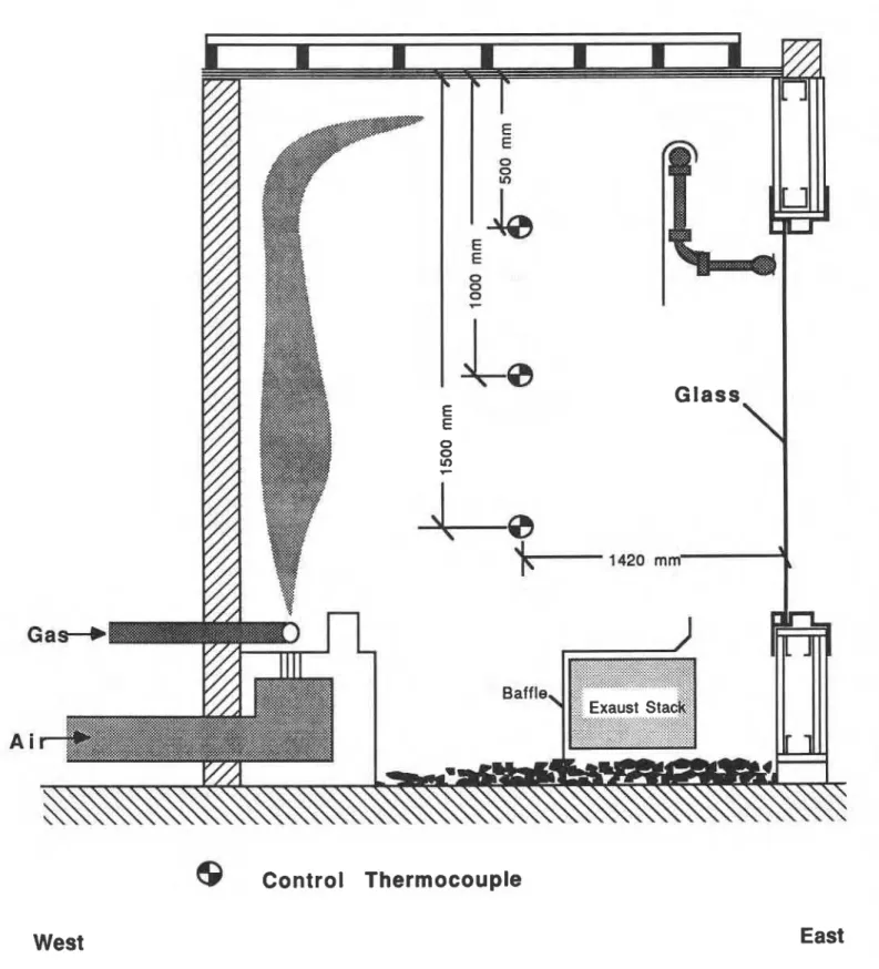
Ref. [15]. The tests were conducted in a burn room with dimensions of 1.83 x 2.44 m and a ceiling height of 3.05 m. Fire exposure to the glass assembly was provided by a linear propane burner installed on the floor adjacent to the west wall (opposite the test assembly), as shown in Figure 1.
The gas and air controls were adjusted manually to maintain the average room
temperature (even with sprinkler operation) as close to the standard time-temperature curve as possible. The sprinklers were permitted to fuse normally. The water flow rate was preset prior to sprinkler activation and adjusted as required during the test.
The results show that in the tests where no sprinklers were used, the average and maximum unexposed temperatures of the tempered glass were 260°C and 290°C, respectively, when the glass broke at 6.5 min. At breakage, the temperature of the exposed side at the centre of the glass was 380°C. In another test, the tempered glass broke at 5 min, and at that time the average temperature was 240°C and the maximum 260°C on the unexposed side, and the temperature on the lower half of the exposed side of the glass was 290°C.
In tests using tempered glass with sprinklers located inside the burn room, the glass did not break. In tests involving wired glass, cracking occurred prior to sprinkler activation. With the sprinkler outside the burn room, a greater number of glass cracks were noted than with the sprinkler inside, probably due to a higher difference in temperature between the fireexposed and unexposed faces. However, with sprinkler protection on either the exposed or unexposed side, the wired glass assembly maintained its integrity.
The sprinkler activation times are shown in Table 1. In all cases with tempered glass, the sprinklers inside the bum room activated early enough to prevent the glass from breaking. In general, the quick-response sprinklers used in the Series 2 and 3 tests operated two to three times faster than the standard sprinklers in Tests 1-4 and 1-5. The fast activation times recorded in Table 1 for Tests 1-1 to 1-3 were due to a high initial fuel input to the bum room, resulting in a more rapid temperature rise than specified by the standard time-temperature curve.
In Test 1-8 on wired glass with a quick-response sprinkler outside the room, the response time was 315 s. At this point, the recorded unexposed g l a s temperatures were in the range at which tempered glass failed in Teas 1-6 (average temperature 262OC) and 1-7 (average temperature 247OC). The wired glass, while cracked extensively, withstood the thermal shock
following sprinkler activation. In Test 1-7, a 150 x 150 mm sheet steel baffle was placed behind a quick-response sprinkler which was outside the fire room, to form a trap for hot air rising along the pane. This reduced sprinkler activation time to 270 s. Although not investigated, this technique may provide a means of ensuring that sprinklers activate early enough to prevent tempered glass from breaking. Thus, tempered glass assemblies could be protected with sprinklers on the unexposed face.
All tests were conducted for a duration of approximately 2 hours. In Tests 1-6 and 1-7, however, the test was terminated soon after the glass broke.
TABLE 1 Sprinkler
Activation Waterflow
I
Glass Time Waterflow per m width Test No. Type1 (s) cumin) (Ymin)/m
1-1 W 112 60-100 54-90 1-2 W 342 80- 120 72-109 1-3 T 1 62 80- 1 10 72- 100 1-4 T 63 100 90 1-5 T 59 100 90 1-6 T
-
-
-
1-7 T-
-
-
1-83 W 315 50-90 45-80 2- 1 T/P 18 100-1 10 67-74 2-2 T/P 21 110 74 3- 1 T 34 100-115 60-68lW
-
wired, T-
tempered, P-
plain, T/P-
double glazing with tempered surface exposed to the fire and plain on the outside2 ~ a r l y sprinkler response due to initial temperatures being too high (see text) 3Sprinkler on the side opposite to fire
The maximum radiant heat flux transmitted through the windows ranged between 4-6 kW/m2. Inside the bum room at the 2 h point into the fire test, the radiant heat flux was calculated to be approximately 100 kW/m2. Law [16] and McGuire [8] have both reported that to ignite cellulosic materials (unpiloted ignition), a heat flux of 33.5
kwh?
(0.8 cal/cm2/s) is required. The radiant heat flux on the unexposed side of the glass in the tests did not exceed20% of this value. Law [16] also reports that a person can tolerate a radiation intensity of
past a window of a compartment on fire, if the window is protected with a sprinkler as described.
Door Tests
NRCC
carried out two tests at theNFL
to determine whether a 51 mm (2 inch) thick oak double-door assembly, which contained wired glass panels, would exhibit sufficient fireresistance either with or without automatic sprinkler protection.
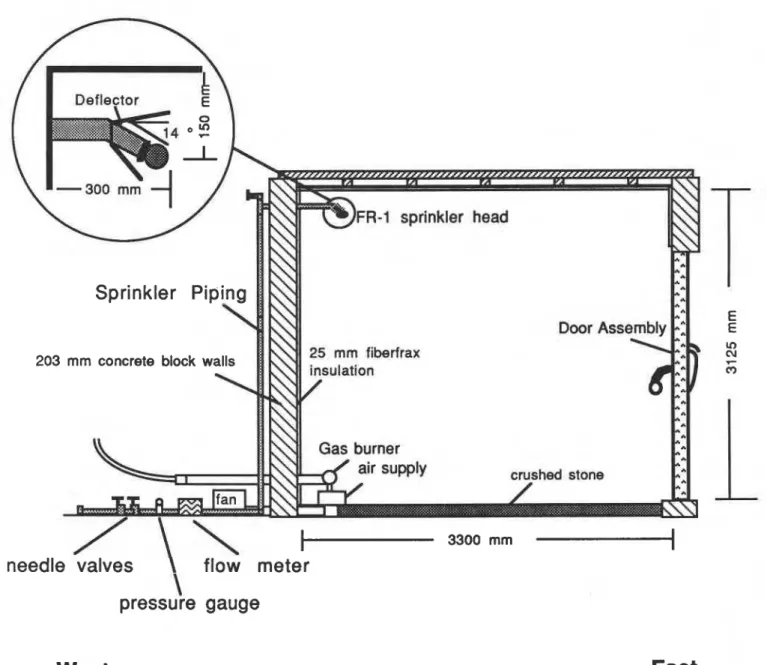
The tests were performed in a burn room with a floor area of 3.6 x 3.6 m and a ceiling height of 3.3 m (see Figure 2). The glass assembly was exposed to fire by means of a linear propane burner installed on the floor adjacent to the west wall (opposite the test assembly). Air for combustion was blown into the burn room by a centrifugal fan and through a steel duct with holes located underneath the propane burner.
The test assembly was a pair of double-leaf exit doors constructed of solid, premium- grade white oak. Two panes of clear wired glass of 6 rnm thickness, 886 mm x 274 mm in size
were installed in the top portion, and two panes of the same thickness and 680 mm x 274 mm in size in the bottom portion of each door. The door assembly was mounted so that the swinging doors would open away from the test room.
A Grinnell Model
FR-
1, fast-response, extended-coverage, horizontal sidewall sprinkler was installed 150 mm below the ceiling in centreline of the west wall, approximately 300 mmaway from it. This location was directly above the propane burner. A steel sheet 0.3 m x 0.2 m in size was placed just below the sprinkler with a slight inclination eastward to protect the burner from the water spray of the sprinkler. This sheet also served to prevent premature activation of the sprinkler head by direct flame impingement on the head,
The sprinkler was a fast-response, solder type with a 74OC (165OF) temperature rating, and it had 12.7 mm orifice with a
K
factor of 79.92. The water flow to the sprinkler was 105 Llmin (27 US gpm) at 188 KPa (27.3 psi) pressure.The room air temperature was monitored by six type
K
20 gauge thermocouples enclosed in Inconel sheaths with 6 rnm outside diameters. The thermocouple beads were positioned at 113 of the room width from the walls.The temperatures of the door and the wired-glass inserts were measured at 12 points on the exposed side as well as on the unexposed side, using 30-gauge chromel-alumel
thermocouples bonded to the surface with a clear epoxy resin. Radiation transmitted through the wired glass was measured with water-cooled radiometers, located 0.6 m away from the centre of two glass inserts (top and bottom).
A preliminary burn test was carried out to establish the propane gas flow rate needed to maintain the test room temperature as close as possible to the standard time-temperam ewe
given in CAN4-S104-M80
.
Following the activation of air supply, the burner was lit manually. The gas input into the burner was manually controlled to follow the predetermined gas flow rate.
In the test with sprinkler protection, the sprinkler was permitted to fuse normally. The water flow rate (105 Urnin) was preset prior to sprinkler activation.
Following the fire performance test without sprinkler protection, the unexposed face of the test assembly was subjected to a hose stream test using a 65
mm
nominal diameter hose with a 29 mm discharge tip nozzle. The nozzle was located 6 m from and on a line normal to the centre of the test assembly.In the test with sprinkler protection, the sprinkler spray was such that the water wetted the whole room and three walls including the wall in which the test assembly was installed. The sprinkler activated fast enough to prevent cracking of the wired glass. The water spray cooled the test room so much that complete combustion of the propane was to achieve. The flame in the room was unsteady and went out at approximately 25 rnin into the test. After re-ignition of the burner, the flame again went out at 32 min. After careful consideration, it was concluded that the test be terminated at 32 min, since steady conditions were achieved within a few minutes of the start and no change in the
fire
performance occurred in the last 20 min. No damage to the door assembly was observed during the test.Because of the sprinkler spray, the average temperature of the test room never exceeded 7S°C. The maximum temperature recorded on the inside surface of the glazing was
approximately 7S°C, and the outside surface temperature was approximately 60°C. The radiation through the glazing was negligible.
In the test without sprinkler protection, the test lasted for 29 min. The doar assembly failed, due to a burn-through at the top ccnner of the door caused by the explosion of hydraulic oil in the closer mechanism (cylinder). The door-closer mechanism was installed in a hollow slot at the top corner of the solid oak door.
The maximum temperature recorded on the inside surface of the glazing was
approximately 850°C, and the outside surface temperature was approximately 450°C. The
maximum radiation through the wired glass, measured approximately 0.15 m away h m the centre of the insert, was less than 5 k ~ l m * , which is approximately 10% of the radiation irradiated on the glass inserts.
The first crack on the glazing appeared at about 1 min 20 s into the test, when the inside and outside surface temperatures of the glazing were approximately 1 10°C and 50°C,
respectively. Cracks on the wired glass were mostly fiom edge to edge in the horizontal direction. Although extensive cracks appeared on the wired glass, the p a l s held together during the fue test. However, with application of the hose stream test, all gladng fell into the burn room.
SUMMARY
Glazing cracks and breaks due to thermal stresses when exposed to fue. When glazing in a window or a door fails, an opening is formed in a compartment boundary. When this happens to external glazing, flames can spread up the face of the building to the floor above or to other nearby buildings. The opening may also allow fresh air into the fire compartment and thus
increase the ventilation rate.
Two kinds of thermal stresses are caused by fue exposure: membrane and bending stresses. The membrane stresses come from the temperature variation along the glass surface and the bending stresses from the temperature variation across the glass pane.
One way of preventing glass from failing when exposed to fire is protecting the glazing with water spray. A uniform water film on the glazing ensures that the heat build-up on the glass is uniform and that it does not reach excessive levels. Also, a water film decreases the
temperature difference across the thickness and reduces bending stresses.
The results of tests conducted at the NFL, NRCC, show that tempered glass assemblies with areas greater
than
the wired-glass areas permitted by the NBCC are able to withstand thestandard fire exposure for at least two hours with sprinkler protection. The results also show that W e s other
than
steel can be used with sprinkler protection.The sprinkler system protecting the glazing also cooled the test room substantially. In tests with windows, the heat input required to follow the standard time-temperature curve in the burn room with a sprinkler on the fire-exposed side was approximately 60% greater than without a sprinkler. In the test with doors, the sprinkler arrangement within the mom prevented a severe fm exposure. The tests indicated that the required fire-resistance qting can be obtained with glazing protected by sprinkler. It is too early, however, to extrapolate the test results. The Fire Research Section, NRCC, is currently carrying out a research project to devise general solutions to protecting glazing exposed to fire.
Further work, both experimental and theoretical, is needed to study the effect of various parameters on the behaviour of glazing exposed to fre when ptected by a water spray. The ability of glazed elements to achieve sufficient periods of fire resistance depends on the type of glazing, its thickness, size, the height-to-width ratio of pane, type of b e , the method of support and retention of the glazing, gasket materials, the form of construction surrounding the glazed area, edge finish, and whether or not the glazed element is subdivided into smaller segments.
Many parameters of the sprinkler operation (such as water flow rate, sprinkler type and location, and time of water application) and their effect on the performance of glazing assembly are to be studied. The time of starting the water spray in relation to the fire ignition is especially important. If water spray is substantially delayed, it could be wunterpductive, since applying cold water to glass heated by hot gases may cause it to fail prematurely. The theoretical basis for the failure of glass under fire exposure has yet to be developed.
ACKNOWLEDGEMENTS
The author gratefully acknowledges the contribution of J.K. Richardson and I. Oleszkiewicz in allowing the use of their experimental data.
Appreciation is extended to J.E. Berndt, D.W. Carpenter, G.P. Crampton,
V. Fortington, M. Ryan and B.C. Taber at the National Fire Laboratory for their assistance in the design, installation, execution and analysis of the tests.
REFERENCES
[I] "Fire-resisting glazing
-
clear borosilicate glass", FPA Information Sheet B17, Fire Protection Association, London, Jan. 1985.[2] Sinha, N.K. "Stress State in Tempered Glass Plate and Determination of Heat-Transfer Rate", Experimental Mechanics, Vol. 18, No. 1, 10 p, Jan. 1978.
[3] "Glass: Science and Technology", Vol. 5, Academic Press Inc., 1980.
[4] Mai, Y.W., Richardson,
K.M.
and Cotterell, B. "Thermal Stress Fracture of Wire Glass", Materiaux et Constructions, Vol. 15, No. 85, pp. 27-31, 1982.[5] Blight, G.E. "Thermal Strains and Fracture of Building Glass", First Australian Conference on Engineering Materials, The University of New South Wales, pp. 685-701, 1974.
[6] Winkelrnann, A. and Schott,
0.
AM. Physik, Vol. 51, pp 730-746,1894.[7] Hovestadt, H. Jenaer Glas, Verlag G. Fischer, Jena, 1900.
[8] McGuire, J.H. "Ignition of Materials Behind Common 118-inch-thick Window Glass", NRCC Technical Note No. 456, Sept. 1965.
[9] Malcomson, R.W. "Report on Window Sprinkler Systems", Underwriters' Laboratories Inc., Report No. NC529, Northbrook,
IL,
July 1969.[lo] Moulen, A.W. and Grubits, S.J. "Water Curtains to Shield Glass from Radiant Heat from Building Fires", Technical Record 4411531422, Experimental Building Station,
Department of Housing and Construction, Australia, July 1975.
[ l 11 Moulen, A.W. and Grubits, S.J. "Water Drenching of Tempered Glass used to Attenuate Radiant Heat, Technical Record 498, Experimental Building Station, Department of Housing and Construction, Australia, July 1983.
[12] Porter, A.M. and Barnfield, J.R. "The Use of Drenchers to Provide Fire Protection to Glazing", Fire Surveyor, pp.4-13, Feb. 1987.
I
I [13] Beason, D. "Fire Endurance of Sprinklered Glass Walls", Fire Journal, pp.43-45, July
1986.
[14] "Recent Developments in External Drencher Protection", Department of Housing and Construction Technical Bulletin, pp.23-25, March 1987.
[15] Richardson, J.K. and Oleszkiewicz, I. "Fire Tests on Window Assemblies Protected by Automatic Sprinklers", Fire Technology, Vol. 23, No. 2, May 1987, pp.115-132. [16] Law, M. "Safe Distances from Wired Glass Screening a Fire", I.F.E. Quarterly, Vol. 29,
West
Control Thermocouple
East
FR-1 sprinkler head E E 25 mm fiberfrax V) cu v c9
\
L
pressure gauge
West
East
T h i s paper i s being d i s t r i b u t e d i n r e p r i n t form by t h e I n s t i t u t e f o r Research i n C o n s t r u c t i o n . A l i s t of b u i l d i n g p r a c t i c e and r e s e a r c h p u b l / c a t i o n s a v a i l a b l e from t h e I n s t i t u t e may be o b t a i n e d by w r i t i n g t o t h e P u b l i c a t i o n s S e c t i o n , I n s t i t u t e f o r Research i n C o n s t r u c t i o n , N a t i o n a l Research C o u n c i l of Canada, O t t a w a , O n t a r i o , KIA 0R6.
Ce document e s t d i s t r i b u 6 sous forme de t i r 6 - + p a r t p a r 1' I n s t i t u t de r e c h e r c h e e n c o n s t r u c t i o n . On peut o b t e n i r une l i s t e d e s p u b l i c a t i o n s de 1 ' I n s t i t u t p o r t a n t s u r les t e c h n i q u e s ou les r e c h e r c h e s e n matisre d e b l t i m e n t e n e c r i v a n t 3 l a S e c t i o n d e s p u b l i c a t i o n s , I n s t i t u t de r e c h e r c h e en c o n s t r u c t i o n , C o n s e i l n a t i o n a l d e r e c h e r c h e s du Canada, Ottawa ( O n t a r i o ) , KlA OR6.