HAL Id: hal-00957532
https://hal.archives-ouvertes.fr/hal-00957532
Submitted on 10 Mar 2014
HAL is a multi-disciplinary open access
archive for the deposit and dissemination of
sci-entific research documents, whether they are
pub-lished or not. The documents may come from
teaching and research institutions in France or
abroad, or from public or private research centers.
L’archive ouverte pluridisciplinaire HAL, est
destinée au dépôt et à la diffusion de documents
scientifiques de niveau recherche, publiés ou non,
émanant des établissements d’enseignement et de
recherche français ou étrangers, des laboratoires
publics ou privés.
The influence of localised size reorganisation on
short-duration bidispersed granular flows
Michela Degaetano, Laurent Lacaze, Jeremy C. Phillips
To cite this version:
Michela Degaetano, Laurent Lacaze, Jeremy C. Phillips. The influence of localised size reorganisation
on short-duration bidispersed granular flows. European Physical Journal E: Soft matter and biological
physics, EDP Sciences: EPJ, 2013, vol. 36, �10.1140/epje/i2013-13036-9�. �hal-00957532�
O
pen
A
rchive
T
OULOUSE
A
rchive
O
uverte (
OATAO
)
OATAO is an open access repository that collects the work of Toulouse researchers and
makes it freely available over the web where possible.
This is an author-deposited version published in :
http://oatao.univ-toulouse.fr/
Eprints ID : 11160
To link to this article
: DOI:10.1140/epje/i2013-13036-9
URL :
http://dx.doi.org/10.1140/epje/i2013-13036-9
To cite this version
: Degaetano, Michela and Lacaze, Laurent and
Phillips, Jeremy C. The influence of localised size reorganisation on
short-duration bidispersed granular flows. (2013) The European
Physical Journal E - Soft Matter, vol. 36 (n° 4). ISSN 1292-8941
Any correspondance concerning this service should be sent to the repository
administrator:
staff-oatao@listes-diff.inp-toulouse.fr
The influence of localised size reorganisation on short-duration
bidispersed granular flows
Michela Degaetano1, Laurent Lacaze2,3,a, and Jeremy C. Phillips1
1 Department of Earth Sciences, University of Bristol, Queens Road, Bristol BS8 1RJ, UK
2 Universit´e de Toulouse; INPT, UPS; IMFT (Institut de M´ecanique des Fluides de Toulouse); All´ee Camille Soula, F-31400
Toulouse, France
3 CNRS; IMFT; F-31400 Toulouse, France
Abstract. We investigate experimentally the runout resulting from the collapse of a granular column containing two particle species that differ in size only. The experimental configuration is strictly two-dimensional (only one particle per width of the experimental tank) and we explore both the role of the initial arrangement and proportion of the two particle sizes in the column, using high-speed videography, and by determining the centres of mass of the big and small particles in the initial column and the final deposit. The duration of the experiment is sufficiently short that large-scale segregation does not occur, however, we find a clear dependence of runout on both initial mixture arrangement and proportion for all conditions. We investigated this observation through detailed analysis of the flow front motion, and identify a characteristic “stopping” phase when dissipation dominates, and we apply a shallow layer model at the flow front to show how the initial mixture arrangement and proportion influence the effective coefficient of friction during emplacement. We find that a bidispersed mixture can induce a larger friction on emplacement than a monodispersed mixture, and the highest coefficient of friction was found for a well-mixed initial arrangement of particles at the proportion that shows maximum horizontal spreading of the flow. These observations suggest that downwards percolation of fine particles takes place at the front of the collapsing column, and so localised size segregation processes at the flow front can control flow mobility. This effect is likely to be important in controlling the mobility of large geophysical flows that occur on finite time scales, and whose deposits typically show granular segregation at the front and edges but not throughout the entire deposit.
1 Introduction
Understanding the mobility of granular materials has im-portant applications to natural hazard prediction for snow avalanches, landslides and debris flows and in industrial and mining processes. These granular materials are char-acterised by containing a range of particle sizes that mod-ifies their dynamics compared to monodisperse granu-lar flows. In particugranu-lar, granu-large-scale segregation is a well-established process in granular flows, which can separate a granular mixture into regions of uniform particle size or density [1–3] if the time scale of the flow is long enough. Here, we define “large-scale segregation” as segregation occurring on a spatial scale that is large compared to the grain size, and therefore involving mesoscopic reor-ganisation of granular media. Although a number of dif-ferent mechanisms can be identified for this process, ki-netic sieving [4] has probably received the most
atten-a e-mail: laurent.lacaze@imft.fr
tion, particularly to model segregation in chute flows [5, 6]. The deposits of large geophysical granular flows do not show large-scale segregation throughout the entire flow, although there is clear evidence of localized small-scale reorganisation particularly at the deposit front and sides (e.g. [7–10]) and occasionally at the deposit top [11].
Laboratory experiments using idealized bidispersed particle mixtures in rotating drums or Couette flow cells have shown that the large-scale rearrangement of a granu-lar material induced by segregation processes typically oc-curs on a time scale that is much longer than that defined by the inverse shear rate or that based on its characteris-tic length and velocity scales (see Golick and Daniels [3] for instance). Instead, localized small-scale reorganisation (termed mixing in previous studies) has been inferred to occur over short time scales from measurements of depth changes in bidispersed granular Couette flow [3]. In the case of a granular collapse, the inverse shear rate is of the order of the total collapsing time scale (Hi/g)1/2, with Hi
oc-curring in larger time scales is not observable on this con-figuration. However, short-time-scale collapse experiments using bidispersed mixtures [12] have highlighted the influ-ence of granular heterogeneity on the enhanced mobility of granular materials. Their results based on the centre-of-mass measurements, and those in other similar exper-iments [13, 14] on an inclined plane invoked the role of segregation as a major control on the flow runout, but the amount of segregation could not be measured during the flow and the role of segregation was inferred from the het-erogeneity of the initial mixture rather than direct obser-vations. These previous experiments [12–14] clearly identi-fied that the runout of a heterogeneous granular material depends on the initial proportion of fine and coarse mate-rial that it contains, even if its duration is sufficiently short that no large-scale segregation is likely to have occurred.
An interpretation of the observations of no large-scale segregation and only local small-scale reorganisation in natural geophysical granular flows is that the flow time scale resulting from a collapse configuration is too short to allow segregation to fully develop. It is therefore im-portant to investigate the influence and phenomenology of short-duration size reorganisation for natural hazard applications, where transient flows of short duration are typical. The aim of the present experiments is therefore to investigate whether short-time-scale processes involving size reorganisation can influence flow runout, or whether the dependence of flow runout on initial composition of fine and coarse materials is independent of segregation. To directly characterise the extent and localisation of these processes, the flow dynamics and deposits formed by gran-ular collapses of bidispersed mixtures of fine and coarse particles in a planar configuration is considered here, fo-cussing on the relationship between the initial centres of mass of the fine and coarse particles and the final de-posit runout. The planar configuration allows the centres of mass of the fine and coarse particles to be resolved at all times during the flow. For granular flows consisting of a single particle size, Lacaze et al. [15] show that a simple two-dimensional experiment can exhibit the same form of scaling laws and qualitative behaviour as previ-ous axisymmetric [16, 17] and quasi-two-dimensional col-lapse experiments [18–20]. These studies emphasize the importance of the influence of the initial aspect ratio on the flow behaviour and runout of the final deposit. This canonical configuration has also motivated several numer-ical studies over the last decade, using both discrete ele-ment modelling [15, 21–23] or a Saint-Venant continuum approach [24–27]. More recently, a visco-plastic model, the µ(I)-rheology [28, 29], has been applied to dense granular flows using a 3D continuum approach [30].
The experiments consist of suddenly releasing a static bidisperse granular column onto a rough horizontal sur-face in a planar configuration. In order to investigate the influence of the granular mixture in this finite-time config-uration, two different sets of experiments are considered. Firstly, as large-scale segregation is not expected on the time scale of the column collapse, initially segregated con-figurations are considered to emphasize the influence of the initial condition. In particular, the initial arrangement
of the granular mass is varied so that for each experimen-tal configuration the initial centre of mass of the small and large particles is altered. In the second set of experiments, the initial proportion of each species is varied in the col-umn. The initial granular column arrangement is expected to strongly influence the final deposit and more particu-larly the contribution of each species to the dynamics of the flow. Moreover, the enhancement of the mass spread-ing in the horizontal direction is known to be influenced by the initial proportion of each species [12]. In order to extract detailed quantitative information from these ex-periments, the apparatus is designed such that individual particles can be tracked independently from high-speed camera acquisitions, although these results are not pre-sented in this paper.
A detailed description of the experimental apparatus and methodology is presented in sect. 2, with sect. 3 pre-senting the experimental results, including qualitative de-scriptions of the flow, analysis of the initial and final posi-tion of the centres of mass, and the flow kinematics. The results are then discussed, followed by the conclusions of this work in sect. 4.
2 Experimental apparatus and methodology
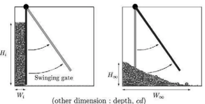
The experiments investigate two-dimensional collapsing granular flows of bidispersed particle mixtures, focussing on the role of initial mixture configuration and granular segregation during the flow. The experiments were con-ducted in a narrow channel of height 500 mm and length 900 mm between glass walls of thickness of 2 mm, as pre-viously used by Lacaze et al. [15]. The experimental con-figuration is shown in fig. 1, with granular collapse being initiated by removing a swinging gate, as used in previ-ous studies [15, 18]; the (x, z)-plane is shown, with the channel spanwise direction, y, being perpendicular to this plane. The vertical direction, z, is aligned with gravity, and (x, z) = (0, 0) is taken at the bottom left-hand cor-ner of the channel. A granular column of initial length Wi
was formed by pouring a mixture of small particles of uni-form diameter dsand big particles of uniform diameter db,
into the region behind the gate to a depth Hi. The initial
aspect ratio of the granular column is defined as a := Hi
Wi
. (1)
A second non-dimensional parameter, the granularity of the column based on small-particle diameter, can be de-fined as
b := Wi ds
(2) and represents the number of small particles which can fit along the base of the column. An additional granularity based on the big-particle diameter can also be defined but is not considered here because the experiments only used a constant ratio ds/db. The number of big particles which
can fit along the base of the column is therefore bds/db.
Fig. 1.Experimental configuration.
is the ratio of the channel wall spacing, cds, to the
parti-cle thickness, ds. The value of c is a measure of the
two-dimensional nature of the flow. For monodispersed par-ticles, the initial geometrical configuration is completely specified by the three non-dimensional parameters a, b, and c (the number of particles, N , involved in the ex-periment scales as ab2). For bidispersed mixtures,
addi-tional consideration of the initial arrangement of small and big particles is required to complete the specification of the initial configuration. Two different granular mate-rials are used to make up the bidispersed mixtures; small particles were spherical polypropylene particles of density ρs= 880 kg m−3 and a diameter ds= 2.5 mm (Precision
Plastic Ball Co., U.K.), and big particles were db= 12 mm
diameter polypropylene discs of 2 mm thickness and den-sity of ρb = 967 kg m−3, which were manufactured from
a sheet of 2 mm thick polypropylene (Durbin Plastics, U.K.). The tolerance on particle size is measured as being ± 0.005 mm. For all experiments, the channel wall spac-ing is kept at a constant value of 3 mm, so that c = 1.2. A similar definition of c based on big-particle thickness would lead to c = 1.5 for the big particles. These values of c are chosen to be in the range of values where crystalli-sation and jamming do not occur [15]. The channel has basal roughness provided by gluing a single layer of small particles to its base.
Two distinctive experimental conditions are investi-gated: i) the variation of the initial arrangement of big and small particles, and ii) the variation of the initial pro-portion of big and small particles. For the first condition, the initial centre of mass of the big and small particles was varied by placing the particle mixture behind the gate in different ways. In this planar configuration, the centre of mass of a system of particle masses m1, m2. . . mnlocated
at positions (x1, z1), (x2, z2) . . . (xn, zn) can be determined
as Cm= Xi + Y j := n X p=1 mprp M , (3)
where rp = xpi+ ypj is the position of particle p and
M = Pn
p=1mp is the total mass, mp being the mass of
each individual particle p. In the following, the indepen-dent centre of mass of each species will also be considered and is denoted C(s)m = X(s)i+ Y(s)j for small particles
and C(b)m = X(b)i+ Y(b)j for big particles. The initial
Fig. 2.Initial granular mixture arrangements: (a) Case 1, fully segregated with all small particles on top of all big particles. (b) Case 2, partially segregated with the centre of mass of the small particles above that of the big particles. (c) Case 3, well-mixed, with the centres of mass of large and small particles in approximately the same position. (d) Case 4, partially segre-gated with the centre of mass of the small particles below that of the big particles. (e) Case 5, fully segregated with all big particles on top of all small particles.
configurations are shown in fig. 2, and consist of com-pletely segregated arrangements (small on top of big and vice versa, denoted here Case 1 and Case 5, respectively; fig. 2a and e), a well-mixed arrangement (uniform repar-tition of particle sizes with depth, denoted here Case 3; fig. 2c), and semi-segregated arrangements (a hybrid con-figuration between the two previous types, denoted here Case 2 and Case 4, respectively; figs. 2b and d). In each experiment, the same mass of small particles (0.017 kg) and the same mass of big particles (0.022 kg) was used, so that the volumes of small and big particles were equal, and the total two-dimensional volume of the particle mixture was approximately 226 cm2. In addition, the gate
posi-tion of 70 mm from one end of the tank, and the initial depth of approximately 380 mm were kept constant, re-sulting in a fixed initial aspect ratio a ≃ 5.4 and a fixed granularity based on small-particle size b = 35. For each experiment, the centre of mass of small and big particles was measured using standard particle tracking algorithms, and these are shown for all arrangements at the initial time t = 0 in fig. 3. It was straightforward to produce initial arrangements with approximately constant centre-of-mass positions for the small and big particles, so ten repeat ex-periments were conducted for each initial arrangement to ensure consistent observations and to estimate their un-certainty.
−0.06 −0.04 −0.02 0 0.02 0.04 0.06 0.2 0.4 0.6 0.8 1 1.2 1.4 1.6 1.8 (X(i)(t=0)−W i/2)/Z(t=0) Z (i) (t=0)/Z(t=0) big particles small particles big particles (average) small particles (average)
Fig. 3.Vertical position of the initial centre of mass Z(i)(t = 0)
as a function of the horizontal position of the initial centre of mass X(i)(t = 0) relative to the horizontal mid-box position
Wi/2, non-dimensionalised with respect to Z(t = 0).
Super-script i is either (s) for small particles (dot symbols) or (b) for big particles (cross symbols). Bold symbols correspond to the mean value of the individual experiments for each Case n (n = 1 . . . 5).
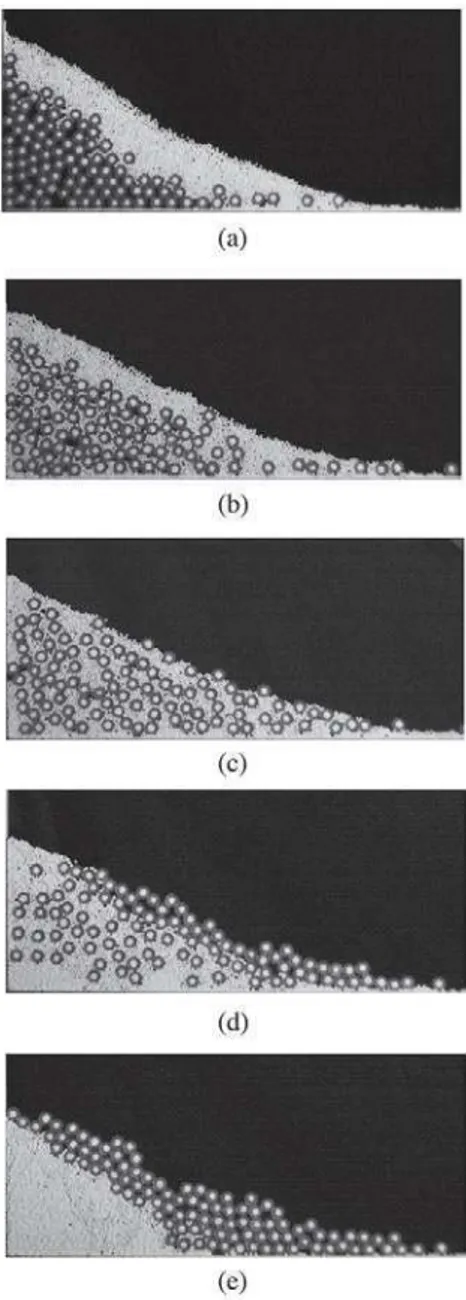
Fig. 4.Initial granular mixture proportions for different small-particle volume fraction: (a) V(s)/V = 0; (b) V(s)/V = 1; (c)
V(s)/V = 0.2; (d) V(s)/V = 0.48.
The second set of experiments investigated the role of the initial proportion of big and small particles in the mix-ture. The initial configurations are shown in fig. 4, and consisted of all big particles (fig. 4a), all small particles (fig. 4b), and mixtures with small-particle volume frac-tions (ratio of volume of small particles to the total vol-ume of particles as initially packed; V(s)/V ) of 0.20 and
0.48 (figs. 4(c) and (d), respectively). The gate position 50 mm from one end of the tank, and the initial depth of approximately 250 mm were kept constant. In
previ-0 0.1 0.2 0.3 0.4 0.5 0.6 0.7 0.8 0.7 0.75 0.8 0.85 0.9 (V (s) +V (b) )/V V(s)/V 4.9 5 5.1 5.2 a (V(s)+V(b))/V(t=0) a
Fig. 5. Variation of initial packing fraction (V(s)+ V(b))/V
and initial aspect ratio a with volume fraction of small particles V(s)/V .
ous bidispersed experiments [12,14], the small-particle vol-ume fraction was found to provide a leading-order control on the flow runout; the mixture proportions used here are representative of the range of runouts previously ob-served. Differences in mixture composition produced only a very small difference in initial packing (defined here as (V(s)+ V(b))/V ) and hence initial aspect ratio, a (fig. 5).
For a small-particle mass fraction from 0 to 0.9, the ini-tial packing fraction varied from 0.71 (all big particles) to a maximum of 0.88 (small-particle mass fraction of 0.8), and the initial aspect ratio varied in a very narrow range from 4.96 to 5.08 (fig. 5). For this set of experiments, the granularity based on small-particle size was b = 25.
In the first set of experiments, the small-particle vol-ume fraction is V(s)/V = 0.5 for all Cases and in the
second set of experiments, the initial vertical position of the centre of mass is such that Z(s)(t = 0)/Z(t = 0) =
Z(b)(t = 0)/Z(t = 0) = 0.5. In the parameter space
con-sidered here, Case 3 of the first set of experiments and the case V(s)/V = 0.48 of the second set of experiments are
nearly the initial condition for which only b varies.
3 Results
Qualitative observations and quantitative characteristics of the final deposit are presented in this section for the two experimental conditions: initial arrangement and initial proportion described in sect. 2. In both cases, multiple runs are made at the same parameter settings and mean and dispersion of the resulting data are shown. In addition, the dynamics of the front is also analysed to provide some information on the dissipation of the system.
3.1 Qualitative observations
A typical evolution of a column collapse for a granular mixture is shown in fig. 6. The different images, obtained
Fig. 6.High-speed video images of the collapse for Case 3 at t = 0 (a), t = 0.2 s (b), t = 0.4 s (c) and t = 0.6 s (d).
with a Redlake Motionscope 2000S high-speed video cam-era at a frame rate of 250 frames per second, correspond to Case 3 from initial time t = 0 (fig. 6a, similar to fig. 2c) to final time tf (fig. 6d). The evolution is very similar to
the planar collapse obtained for monodisperse particles (see Lacaze et al. [15]). Images of typical deposit shapes for the different configurations studied in this paper are shown for the initial arrangement set of experiments in fig. 7 and for the initial proportion set of experiments in fig. 8.
Figures 6 to 8 show that no obvious segregation of the two species is obtained in this experimental configuration, in contrast to experiments that show clear size separation, such as granular avalanches over an inclined plane [13] for instance. This indicates that the characteristic time scale of size segregation is at least comparable to, or much longer than, the time scale of the granular collapse over the horizontal plane. It can be noted from fig. 7 that the initial separation of the two species remains apparent at the end of the collapse with particles initially at the top of the column being finally at the front of the deposit. Moreover, the shape of the final deposit is clearly influ-enced by the initial proportion (fig. 8) but seems nearly independent of the initial arrangement (fig. 7). We now present quantitative measurements that identify the role of the mixture heterogeneity in influencing the flow dy-namics and deposit characteristics.
3.2 Final deposit characteristics
Figure 9 shows the non-dimensional runout r = (W∞−
Wi)/Wi for the two different sets of experiments; r as a
function of the non-dimensional initial height of the centre
Fig. 7. Final deposit for the different initial arrangement. (a) Case 1, (b) Case 2, (c) Case 3, (d) Case 4, (e) Case 5.
of mass of the big particles, Zb(t = 0)/Z(t = 0) (fig. 9(a))
and as a function of the initial small-particles volume frac-tion V(s)/V (fig. 9(b)). In fig. 9(a), the large cross symbols
show the mean of both Zb(t = 0)/Z(t = 0) and r for each
of the five initial configurations (individual experiments shown as small crosses) while the mean of r is shown as a function of V(s)/V (crosses) with the corresponding error
bars in fig. 9(b) (error bars are obtained from the stan-dard deviation of the repeated runs). For a given V(s)/V ,
the same number of small particles and big particles are used for each run, which means that the uncertainty on this value that arises from the volume measurement is the same for each experimental run (and small) so can be rep-resented by the size of the symbol in fig. 9(a). On the other hand, for the first set of experiments (fig. 9(a)), the value of Zb(t = 0)/Z(t = 0) varies slightly between
Fig. 8. Final deposit for the different initial proportion. (a) V(s)/V = 0; (b) V(s)/V = 1; (c) V(s)/V = 0.2; (d) V(s)/V =
0.48.
for this set of experiments. In fig. 9(a), there is no clear relationship between the non-dimensional runout and ini-tial height of the centre of mass, and there is a significant variability in the runout measurements for each initial con-figuration. The variability in runout measurements means that any influence of the initial arrangement on the final spreading length is not observable at the scale of this ex-periment. In fig. 9(b), there is a clear trend regardless of the variability expressed by the error bars, indicating that the runout r is larger for a mixture than for monodisperse collapses. This observation was also reported by previous work with comparable configuration [12]. In the present case, the maximum runout is obtained for V(s)/V ≃ 0.5.
In order to refine the characterisation of the final de-posit and to show its relationship to the initial mixture, the centre of mass for each run is shown in fig. 10. In par-ticular, the effect of the initial arrangement is shown in fig. 10(a), where the non-dimensional horizontal compo-nent of the final centre of mass X(tf)/Z(t = 0) is plotted
as a function of the non-dimensional vertical component of
0.5 1 1.5 4.5 5 5.5 6 6.5 7 7.5 Z(b)(t=0)/Z(t=0) r 0 0.2 0.4 0.6 0.8 1 3.5 4 4.5 5 5.5 V(s)/V r (a) (b)
Fig. 9. Non-dimensional runout r as a function of Zb(t = 0)/
Z(t = 0) (a) and V(s)/V (b). In (a), large symbols correspond
to mean value over the different run of each Case and small symbols show the data for each individual run. In (b), mean values and error bars are shown.
the initial centre of mass of big particles Z(b)(t = 0)/Z(t =
0). X(tf)/Z(t = 0) increases with the height of big
parti-cles in the initial column, and this trend is weakly appar-ent in the non-dimensional runout r in fig. 9(a). Moreover, the effect of the initial proportion V(s)(t = 0)/V on the
non-dimensional horizontal component of the final centre of mass X(tf)/Z(t = 0) (see fig. 10(b)) confirms broadly
the trend for runout r shown in fig. 9(b). The maximum transport is obtained for a mixture of the two species, with that for monodisperse configurations (figs. 4(a) and (b)) being smaller. However, the maximum transport is now obtained for V(s)/V = 0.3 (instead of V(s)/V = 0.5 for
the maximum r in fig. 9(b)) reflecting the difference in shape of the deposits (see figs. 8(c) and (d)).
To assess the role of the initial arrangement, the po-sition of each species in the final deposit relative to their position in the initial column can be determined. The non-dimensional horizontal component of the final centre of mass X(i)(t
f)/Z(t = 0) is plotted as a function of the
non-dimensional vertical component of the initial centre of mass Z(i)(t = 0)/Z(t = 0) in fig. 11 for each species, i.e.
(i) is either (s) (dots) or (b) (crosses) for small particles and big particles, respectively. As before, large symbols
0.5 1 1.5 0.58 0.6 0.62 0.64 0.66 0.68 0.7 0.72 0.74 Z(b)(t=0)/Z(t=0) X(t f )/Z(t=0) 0 0.2 0.4 0.6 0.8 1 0.65 0.7 0.75 0.8 0.85 V(s)/V X(t f )/Z(t=0) (a) (b)
Fig. 10. Non-dimensional horizontal component of the final centre of mass X(tf)/Z(t = 0) as a function of (a) Zb(t =
0)/Z(t = 0) (small crosses show each individual run) and (b) V(s)/V . Same legend as fig. 9.
correspond to the mean value for each Case while small symbols show each individual run, and there is one cross and one dot symbol for each run. To identify the two data-points (a dot and a cross) for each run, it should be noted that the smallest Z(b)(t = 0)/Z(t = 0) corresponds to the
largest Z(s)(t = 0)/Z(t = 0) and vice versa, and all the
other results follow with Z(b)(t = 0)/Z(t = 0) + Z(s)(t = 0)/Z(t = 0) ≃ 1. It is therefore shown that the higher a species in the initial column, the further its position in the final deposit, as also shown in fig. 7. Moreover, for a sim-ilar value Z(s)(t = 0)/Z(t = 0) ∼ Z(b)(t = 0)/Z(t = 0),
associated with two different Cases (Case 1 and Case 5 or Case 2 and Case 4), it can be seen that big particles tend to travel further than small particles. This trend is more accentuated for large Z(i)(t = 0)/Z(t = 0) and
tends to disappear for the well-mixed Case 3 which sat-isfies both Z(s)(t = 0)/Z(t = 0) ∼ Z(b)(t = 0)/Z(t = 0)
and Z(b)(t = 0)/Z(t = 0) + Z(s)(t = 0)/Z(t = 0) ∼ 1.
3.3 Characterisation of the dynamics
In this section, the time evolution of the granular medium is analysed in order to identify its dynamics during the
0.2 0.4 0.6 0.8 1 1.2 1.4 1.6 1.8 0.4 0.5 0.6 0.7 0.8 0.9 1 1.1 Z(i)(t=0)/Z(t=0) X (i) (t f )/Z(t=0)
Fig. 11.Non-dimensional horizontal position of the centre of mass of the final deposit for both particle sizes X(i)(t
f)/Z(t =
0) as a function of their non-dimensional initial vertical centre of mass position Z(i)(t = 0)/Z(t = 0), where (i) is (s) for small
particles (small dots) and (b) for big particles (small crosses). Large symbols denote mean values for each independent Case.
collapse and, more particularly, the dissipation associated with the effective friction of the material. For this purpose, the shallow-water approximation is used as previously ap-plied to granular collapse [24, 25]. The one-dimensional set of equations using the Coulomb model with constant friction µ reads ∂h ∂t + ∂hu ∂x = 0, (4) ∂u ∂t + u ∂u ∂x = −gK ∂h ∂x− µg,
where h and u are the height and horizontal velocity, re-spectively, g is the gravity, µ the effective constant friction and K is the Earth pressure coefficient defined by Savage and Hutter [31]; this coefficient is often set to unity but its exact value is not important in this analysis. The term −µg corresponds to a dissipative term induced by friction of the material at the base. In what follows, the effective friction µ is characterised by the dynamics of the system at the front.
An example of the front evolution W (t) is shown in fig. 12 for the different initial arrangements (Case n, n = 1 . . . 5). The individual run used here to represent each Case has been chosen to have the runout r that most closely matches that of the mean of each Case (fig. 9(a)). The results for the different Cases are qualitatively simi-lar but quantitative differences are apparent, particusimi-larly in terms of the maximum velocity and acceleration for each different Case. Notably, the well-mixed Case 3 has the highest maximum velocity and initial acceleration, and consequently the largest deceleration. As deceleration is induced by dissipation associated with friction at the base, and therefore with the value of µ in the set of equa-tions (4), it is instructive to focus on the front position evolution W (t), for which height and velocity are hf = 0
0 0.1 0.2 0.3 0.4 0.5 0.6 0.7 0.8 0 5 10 15 20 25 30 35 40 t (s) W−W i case 1 case 2 case 3 case 4 case 5
Fig. 12. Front position W − W − i as a function of t for the different Case n, n = 1 . . . 5. can be simplified to duf dt = −gK µ ∂h ∂x ¶ f − µg, (5)
where subscript f stands for “front” localisation. It is worth noting that if, in eq. (4), µ is not as simple as constant Coulomb friction but has a more complex de-pendence on the flow characteristics, the front eq. (5) is unchanged, with indeed a constant friction term. For ex-ample, Pouliquen and Forterre [32] defined the following basal friction based on the local height h and velocity u:
µ(h, u) = µ1+
µ2− µ1
h3/2√gβ
udL + 1
, (6)
where µ1, µ2, β and L are dimensionless constants that
only depend on the material properties and d is the grain diameter. As the front is defined by hf = 0 and uf 6=
0, then (6) reduces to µ(hf, uf) = µ2 constant, which
is therefore similar to the constant friction µ defined in eq. (5).
In eq. (5) it is shown that the time evolution of the front duf/dt = d2W/dt2 is therefore controlled by a
source term induced by the slope of the height h and a dissipation due to the friction at the base. It can be seen that −gK(∂h/∂x)f is always a source term since
(∂h/∂x)f ≤ 0.
The time evolution of the quantity uf is shown in
fig. 13 for Case 1 (crosses) and Case 3 (dots). The evolu-tion of the front velocity can be divided into two dominant phases: an acceleration phase at early times, and then a deceleration until the granular medium reaches its equi-librium state. The delimitation between the two phases occurs at a time tp, where tp ≃ 0.25 s for Case 1 and
tp≃ 0.3 s for Case 3. The first phase is mainly controlled
by the source term in eq. (5) since gradients of h are impor-tant at early times (see fig. 6(b)). On the other hand, dur-ing the second phase, dissipation becomes dominant since uf decreases (see fig. 13). In particular, a linear
relation-ship between uf and t is observed in this phase (dashed
0 0.1 0.2 0.3 0.4 0.5 0.6 0.7 0.8 0 0.1 0.2 0.3 0.4 0.5 0.6 0.7 0.8 0.9 1 t (s) u f (m/s) case 1 case 3
Fig. 13.Front velocity uf = dW/dt as a function of time for
Case1 and Case 3. Dashed line correspond to the best linear fit for t > tp(see text for details).
lines), indicating that the right-hand side of eq. (5) is con-stant, and therefore that (∂h/∂x)f is constant.
During the dissipation phase t > tp, our
experimen-tal observations (see figs. 6(c), (d), 7 and 8) and numeri-cal results obtained by Mangeney et al. [25] suggest that (∂h/∂x)f = 0, and so eq. (5) can be thus simplified to
duf
dt = −µg, for t > tp. (7) In this case, an evaluation of the effective friction µ can be performed for the different experiments using a linear fit of uf(t > tp) (see dashed lines in fig. 13) and the results
are shown in fig. 14. These plots show how the variation of the initial arrangement (fig. 14(a)) and the variation of the initial proportion (fig. 14(b)) influence the effective friction coefficient.
In our experiments, the base is made of glued small particles, so the friction at the base depends on both small particles moving on small particles and big particles mov-ing on small particles. Moreover, the coefficient of friction associated with small-small particle contacts, µs, is larger
than the coefficient of friction associated with big-small particle contacts, µb [13]. µs and µb are obtained from
the monodisperse configurations with only small particles flowing over a small particle base, V(s)/V = 0.87, and only big particles flowing over a small particle base, V(s)/V = 0
respectively (see fig. 14(b)). We thus find µs ∼ 0.29 and
µb∼ 0.18. It can be first noted that µ ≥ µb for the
differ-ent configurations (see figs. 14(a) and (b)), as expected, but that µ is not necessarily smaller than µs, meaning
that a bidisperse mixture can induce larger friction than the monodisperse configuration. This observation is con-sistent with the fact that the largest friction is obtained for an initially well-mixed configuration (fig. 14(a)) for which the proportion of small particles and big particles at the base and at the front is of the same order. Moreover, it is also shown that this effect seems to be even more efficient for a volume fraction V(s)/V ∼ 0.2 (fig. 14(b)).
0.5 1 1.5 0.22 0.24 0.26 0.28 0.3 0.32 0.34 Zb(t=0)/Z(t=0) µ 0 0.2 0.4 0.6 0.8 1 0.2 0.25 0.3 0.35 0.4 V(s)/V µ (a) (b)
Fig. 14. Effective friction coefficient µ obtained from eq. (7) as a function of (a) Zb(t = 0)/Z(t = 0) and (b) V(s)/V .
4 Conclusion
In this paper, the granular collapse of a bidisperse mix-ture has been investigated using the planar experimental apparatus described by Lacaze et al. [15]. This configura-tion allows the centre of mass of big and small particles in the initial mixture and the final deposit to be determined. The influence of both the variation of the initial arrange-ment and the variation of the initial proportion of big and small particles has been demonstrated for both final de-posit characteristic lengths and dynamical properties such as the effective friction at the base of the front. A model of the frontal dynamics shows that the effective coefficient of friction of the mixture at the front of the collapsing col-umn, µ, depends on both the initial arrangement and the initial proportion. This analysis shows explicitly how the frictional resistance to motion is modified by bidispersed granular mixtures as compared to monodispersed granular flow in otherwise identical conditions. Finally, the increase of the friction term for well-mixed configuration and es-pecially for a proportion corresponding to the maximum horizontal spreading, suggests that downward percolation of small particles through large ones take place at the front of the collapsing column, and implicates this localised re-organisation of the two species with increased mobility of the flow front.
LL was supported by a Marie-Curie IntraEuropean fellowship when carrying the experiments. JCP acknowledges financial support from the Royal Society. We gratefully acknowledge an anonymous reviewer and Lydie Staron for helpful comments that improved the manuscript.
References
1. M.E. Mobius, B.E. Lauderdale, S.R. Nagel, H.M. Jaeger, Nature 414, 270 (2001).
2. T. Shinbrot, Nature 429, 352 (2004).
3. L.A. Golick, K.E. Daniels, Phys. Rev. E 80, 042301 (2009). 4. J. Bridgwater, Powder Technol. 15, 215 (1976).
5. S.B. Savage, C.K.K. Lun, J. Fluid Mech. 189, 311 (1988). 6. J.M.N.T. Gray, A.R. Thornton, Proc. R. Soc. London, Ser.
A 461, 1447 (2005).
7. M.R. Mudge, Geol. Soc. Am. Bull. 76, 1003 (1965). 8. L. Siebert, J. Volcanol. Geoth. Res. 22, 163 (1984). 9. G. Wadge, P.W. Francis, C.F. Ramirez, J. Volcanol. Geoth.
Res. 66, 309 (1995).
10. C.G. Johnson, B.P. Kokelaar, R.M. Iverson, R.J. LaHusen, M. Logan, J.M.N.T. Gray, J. Geophys. Res. 117, F01032 (2012).
11. J.E. Clavero, R.S.J. Sparks, H.E. Huppert, W.B. Dade, Bull. Volcanol. 64, 40 (2002).
12. J.C. Phillips, A.J. Hogg, R.R. Kerswell, N.H. Thomas, Earth Planet. Sci. Lett. 246, 466 (2006).
13. C. Goujon, B. Dalloz-Dubrujeaud, N. Thomas, Eur. Phys. J. E 23, 199 (2007).
14. F. Moro, T. Faug, H. Bellot, F. Ousset, Cold Reg. Sci. Technol. 62, 55 (2010).
15. L. Lacaze, J.C. Phillips, R.R. Kerswell, Phys. Fluids 20, 063302 (2008).
16. E. Lajeunesse, A. Mangeney-Castelnau, J.-P. Vilotte, Phys. Fluids 16, 2371 (2004).
17. G. Lube, H.E. Huppert, R.S.J. Sparks, M.A. Hallworth, J. Fluid Mech. 508, 175 (2004).
18. N.J. Balmforth, R.R. Kerswell, J. Fluid Mech. 538, 399 (2005).
19. E. Lajeunesse, J.B. Monier, G.M. Homsy, Phys. Fluids 17, 103302 (2005).
20. G. Lube, H.E. Huppert, R.S.J. Sparks, A. Freundt, Phys. Rev. E 72, 041301 (2005).
21. L. Staron, E.J. Hinch, J. Fluid Mech. 545, 1 (2005). 22. R. Zenit, Phys. Fluids 17, 031703 (2005).
23. L. Lacaze, R.R. Kerswell, Phys. Rev. Lett. 102, 108305 (2009).
24. R.R. Kerswell, Phys. Fluids 17, 057101 (2005).
25. A. Mangeney-Castelnau, F. Bouchet, J.-P. Vilotte, E. La-jeunesse, J. Geophys. Res. 110, B09103 (2005).
26. E. Larrieu, L. Staron, E.J. Hinch, J. Fluid Mech. 554, 259 (2006).
27. E.E. Doyle, H.E. Huppert, G. Lube, H.M. Mader, R.S.J. Sparks, Phys. Fluids 19, 106601 (2007).
28. GDR MiDi, Eur. Phys. J. E 14, 341 (2004).
29. P. Jop, Y. Forterre, O. Pouliquen, Nature 441, 727 (2006). 30. P.-Y. Lagr´ee, L. Staron, S. Popinet, J. Fluid Mech. 686,
378 (2011).
31. S.B. Savage, K. Hutter, J. Fluid Mech. 199, 177 (1989). 32. O. Pouliquen, Y. Forterre, J. Fluid Mech. 453, 133 (2002).