HAL Id: cea-02339116
https://hal-cea.archives-ouvertes.fr/cea-02339116
Submitted on 13 Dec 2019
HAL is a multi-disciplinary open access
archive for the deposit and dissemination of sci-entific research documents, whether they are pub-lished or not. The documents may come from teaching and research institutions in France or abroad, or from public or private research centers.
L’archive ouverte pluridisciplinaire HAL, est destinée au dépôt et à la diffusion de documents scientifiques de niveau recherche, publiés ou non, émanant des établissements d’enseignement et de recherche français ou étrangers, des laboratoires publics ou privés.
thermal-hydraulics of ASTRID-like sub-assembly
Thierry Cadiou, Francisco Acosta
To cite this version:
Thierry Cadiou, Francisco Acosta. The impact of the fuel bundle deformation on the
thermal-hydraulics of ASTRID-like sub-assembly. NUTHOS-12 (12th International Topical Meeting on Nuclear Reactor Thermal-Hydraulics, Operation and Safety), Oct 2018, Qingdao, China. �cea-02339116�
Abstract No: Please be sure to fill in the number of the submitted abstract for this full text Paper No.:
The impact of the fuel bundle deformation on the thermal-hydraulics of
ASTRID-like sub-assembly
Thierry CADIOU, Francisco ACOSTA1 - CEA, DEN, DER, SESI, F-13108, Saint Paul lez Durance, France
thierry.cadiou@cea.fr
ABSTRACT
The Sodium-cooled Fast Reactor (SFR) fuel sub-assembly irradiation leads to a substantial modification of its geometry and mechanical properties. Indeed, it produces void swelling and creep on the clad that increase the fuel pin diameter and its bending. As a result, the sub-assembly flowrate could be reduced, and hence the sodium temperature would increase. In order to guarantee the fuel pin clad mechanical strength in operation, which largely depends on its temperature, it is proposed to evaluate the maximum temperature reached by the clad for a deformed sub-assembly. The objective of this study is to provide the sensitivity of thermal-hydraulics to the fuel bundle deformation in order to propose criteria on the maximum admissible strain.
To address this issue, the impact of a SFR fuel bundle diametral strain on the thermal-hydraulics is studied by means of Computational Fluid Dynamics (CFD) simulations with the industrial code STAR-CCM+ [1]. A nominal geometry of sub-assembly and a highly deformed one are considered. The modification on flowrate for this latter geometry is firstly determined by a method that estimates the relationship between the pressure loss and the flowrate in the sub-assembly. CFD simulations with the updated flowrate used as boundary conditions for the deformed geometry are then run and compared to the results obtained for the nominal geometry. By this way, the consequences of the fuel pin deformation on the clad temperature and velocity field are evaluated.
This work, presented with conservative hypothesis and based on a geometry that is deformed beyond the recommended limits, concludes on the high sensibility of the deformation on the clad temperature. On the other hand, clad swelling and creep also depend on temperature, therefore the temperature increase in the sub-assembly resulting from the lower flowrate in sub-assembly could also significantly modify its geometry. Given the perturbation found on the clad temperature, it is suggested to adopt a coupled approach between thermal-hydraulics and thermomechanics to better assess the sub-assembly evolution during irradiation.
KEYWORDS
Liquid sodium, Sodium-cooled Fast Reactor, thermal-hydraulics in sub-assembly, CFD.
INTRODUCTION
The CEA is involved in long term R&D programs on Sodium-cooled Fast Reactor and is currently working on the ASTRID project [2]. Among the domains of studies, a thorough understanding of the core thermal-hydraulics and in particular of the geometrical modification induced by irradiation on the fuel assembly is a major concern. Indeed, this will make the global temperature of the sub-assembly progressively increase. As a result, it will influence the clad mechanical strength and therefore the lifespan of the sub-assembly in reactor.
Thanks to numerical simulation using the CFD industrial STAR-CCM+ software, the thermal-hydraulics of a SFR sub-assembly is evaluated in nominal condition for the non-deformed and deformed geometries, the latter one being characterized by fuel pins with a larger diameter and updated boundary conditions for the sub-assembly flowrate.
Abstract No: Please be sure to fill in the number of the submitted abstract for this full text Paper No.:
from the effects of a geometry modification of the sub-assembly on thermal-hydraulics.
1
SFR FUEL BUNDLE DEFORMATION MECHANISMS AND CAUSES
In a SFR reactor, the fuel pin is submitted to different solicitations, leading to its deformation. After presenting the ASTRID-like sub-assembly, the causes and the resulting deformation mechanisms are explained.
1.1 The ASTRID-like sub-assembly
The ASTRID-like sub-assembly is composed of several dozens of fuel pins, cylindrical steel clads that contain the fissile and fertile fuel pellets. A spacer wire turns around each pin helically in order to maintain it in its initial position and has also the advantage to mix the sodium flow. The sub-assembly and fuel pins are drawn on Fig. 1.
Fig. 1 A fuel assembly (left), a pin with its spacer wire (centre) and detail of a fuel pin sub-assembly (right)
In addition, the hexagonal geometry of the sub-assembly is characterized by the distance between two neighbouring pins called the fuel pin pitch p, the pin diameter 𝐷𝐶𝐿𝐴𝐷, the wire diameter 𝐷𝑤𝑖𝑟𝑒 and the
spacer wire pitch (cf. Fig. 6).
1.2 The causes of fuel deformation
During irradiation, the fuel pin geometry is in constant evolution, depending on its temperature, internal pin pressure and the irradiation dose received. The main causes of the fuel pin deformation, are thermal expansion, creep and swelling.
The thermal expansion corresponds to a general increase in volume of a material as the temperature rises.
Creep is the tendency of a material to permanently deform under the effects of a constant stress. It is time-dependent and is only evidenced after long time in reactor nominal condition. Creep can be of two different natures: the thermal creep linked to the high temperature of the material and the irradiation creep correlated to the received irradiation dose. The high temperature of the clad enhances the viscoplastic effects resulting from the force exerted by the fission gas on the inner side of the clad. Thermal creep is present for clad temperature Tclad/Tmelting>0,3 [3], with Tmelting the melting temperature, hence approximately 220°C. Creep is however small around this temperature but rapidly increases as the temperature gets closer to the clad melting point. Due to the neutronic flux, irradiation also increases the creep rate over the one due to thermal creep and induces creep at temperatures
Abstract No: Please be sure to fill in the number of the submitted abstract for this full text Paper No.:
where the thermal creep would not be present.
Void swelling appears when energetic neutrons impact atoms of the crystal structure of the clad material. Atoms leave their original position, creating vacancies in the structure. More precisely, if neutrons are energetic enough, part of this energy can be transferred to the displaced atoms, which, in turn, can produce a real cascade of displacements in the crystal structure. At high temperature, recombination of atoms in a different state of equilibrium is generally achieved. At medium temperature, corresponding approximately to the core temperature, the vacancies can accumulate that leads to a general increase of the material volume. As a result, mechanical properties of the clad material, such as its ductility and resilience, can significantly change. The fuel pin clad is particurlaly sensitive to void swelling, leading to an increase of its diameter. Probability of clad failure becomes therefore higher. For that reason, a limit on the acceptable clad volume swelling is fixed to 6 % [4].
1.2 Consequences of these solicitations on the fuel pins
These solicitations modify the geometry of the fuel pin, especially its diameter and its bending.
The fuel pin Bowing is the result of a temperature gradient between two opposite faces of the fuel pin. In reactor, this is in general the case between the nearest and furthest part of the fuel pin relatively to the center of the reactor core. In order to accommodate to the thermal dilatation, this induces a flexion of the pin on its axis.
This phenomenon is represented on Fig. 2 where the fuel pin deformation is caused by the differential thermal expansion between the red face and the blue one.
Fig. 2 Simplified illustration of bowing
Helical flexion is a bending phenomenon of the pin due to the differential thermal expansion between the clad and its own spacer wire. The result of this deformation is visualized on the left representation of Fig. 3. As the fuel pin gets into contact with the wrapper tube or a neighbouring wire at different periodic axial positions, corresponding to a rotation of 60° of the spacer wire (1/6 of the spacer wire pitch), this will induce additional distortion in the clad, creating such impressive oscillations shown on the right picture of Fig. 3 .
In general, helical flexion appears first on the pins close to the wrapper tube and then propagates to the pins of the inner rows of the fuel sub-assembly.
Abstract No: Please be sure to fill in the number of the submitted abstract for this full text Paper No.:
Fig. 3 Simplified illustration of helical flexion (left) and its appearance in SFR fuel pins (right) If a single fuel pin is considered, its radial deformation due to swelling or creep is uniform. As the pin is surrounded by neighbouring pins and rapidly get into contact with them in reactor, the fuel pin diameter will preferentially increase in perpendicular direction to the contact to produce the oval shape represented on the left Fig. 4. This deformation is however partially counter-balanced by the force applied by the internal fission gas on the pin, as represented on the right Fig. 4.
Fig. 4 Effect of ovalization in a SFR (left) - Illustration of ovalization (right)
Among the different deformations of the fuel pin discussed above, the hydraulic diameter of the sub-assembly is mainly affected by the pin diametral deformation. The effects of bending and helical flexion are therefore ignored in the following of the paper.
Abstract No: Please be sure to fill in the number of the submitted abstract for this full text Paper No.:
2
NUMERICAL APPROACH
The impact of the fuel bundle deformation on thermal-hydraulics is studied by means of CFD simulation with the commercial software STAR-CCM+. The modelling choices for meshing and boundary conditions are first explained. The results are then presented for the different simulations.
2.1 CFD modelling
Flow in a sodium sub-assembly is always turbulent (Re~50000) in nominal condition. A RANS approach with the k-model and the wall function called “all y+ Wall Treatment “ is used. The choice of this turbulence model is justified by previous studies leading to similar results with the k- high and low Reynolds as well as with the k- SST turbulence model [5].
The modelled geometry consists of a sub-assembly of 217 wire-wrapped pins surrounded by a hexagonal wrapper tube (see Fig. 5). The main geometrical parameters of the modelled sub-assembly are summarized hereafter:
Fig. 5 Fuel bundle representation in the CFD calculation
Two geometries that correspond respectively to the nominal geometry and a deformed geometry with an arbitrary increase of 6% of its pin diameter are assessed. This diametral deformation is representative of the contribution of fuel swelling and creep and exceeds the acceptable volume deformation of 6%, mentioned above. The spacer wire is considered as non-deformed although it is also submitted to swelling effects.
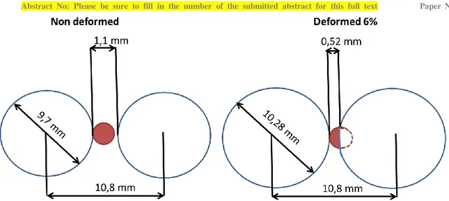
The effect of the diameter increase for two neighbouring pins is represented on Fig. 6. In order to simplify the meshing, two modifications of the real geometry are proposed for the modelling. Small interpenetration between the pin and its own wire is firstly done so that the contact is not linear. From previous analysis, this assumption does not alter results [6, 7]. Secondly, the modelled spacer wire is allowed to go into the neighbouring pin while the spacer wire would have crushed in reality. As the fluid cross-section is only increased by 5.9 %, whereas the pin diameter expansion of 6% decreases the fluid cross-section by more than 31 %, this simplification is also considered to be acceptable.
Abstract No: Please be sure to fill in the number of the submitted abstract for this full text Paper No.:
Fig. 6 Detail of the two neighbouring pins for the nominal (left) and 6% deformed geometry (right)
2.2 Sodium thermophysical properties
Constant thermophysical properties for sodium are considered, at a temperature of 475°C that is an average value between the inlet and the average outlet sodium temperature in the fuel bundle, respectively of 400°C and 550°C [8].
2.3 The fuel bundle meshing
The STAR-CCM+ software allows to mesh the fluid by trimmed, tetrahedral or polyhedral cells. The polyhedral meshing, which is a good comprise between the number of cells and the quality of the results with one prism layer, is selected. In order to reduce the number of cells, the meshing is firstly created on a reduced geometry of 0,2 m in height and is then stretched by a factor of 4. As the radial gradients are larger than the axial ones, previous study concluded that this strategy does not degrade the results [9]. The final meshing is represented on Fig. 7.
Fig. 7 Mesh of the sub-assembly (left) and detail of the spacer wire (right)
On the 6% deformed geometry, the meshing takes into account the interpenetration of the spacer wire in the neighbouring pins.
Abstract No: Please be sure to fill in the number of the submitted abstract for this full text Paper No.:
0.42mm. The number of cells is 43 millions for the non deformed geometry and 55 millions for the deformed one.
CFD calculations are performed with wall function based on the “all y+ Wall Treatment “model that represents the shear stress, turbulent production and dissipation near the sub-assembly walls. Depending on the value of the dimensionless distance to the wall y+, this hybrid approach gives results similar to the “low y+ treatment” as long as y+ is lower than 5 and to the “high y+ treatment” if y+ is greater to 30. Reasonable results are also get for intermediate meshes where the cell centroid falls between the two. However, the aim should be to have either y+<5 including a well resolved viscous sublayer or 30<y+<100.
In the present case, 15% of cells are in the range 5<y+<30, essentially concentrated near the contact line between pins and wire and less than 10% are above 100, therefore the meshing is judged to be acceptable.
2.4 Boundary conditions
The fuel bundle studied is composed of two fissile zones separated by a fertile one. The wrapper tube and spacer wires are supposed adiabatic. The axial linear power profile is derived from neutronics calculation. In the CFD calculation, the heat flux profile and not the linear power profile is imposed to all the pins. For that purpose, the differences of surface between the two geometries are taken into account to evaluate the heat flux in order to keep the same total power in the sub-assembly.
The sodium temperature is fixed to 400°C and the sodium flowrate with a uniform velocity to 27,3 kg/s at the inlet of the fuel bundle. At the outlet, a constant pressure is provided. With these conditions, the average sodium temperature at the outlet of the heated column is 550°C.
For the deformed geometry, two cases are simulated. First, the same flowrate as for the nominal geometry is kept. Then, a modified flowrate is assessed in order to have the same pressure drop for all the sub-assemblies as it is for the nominal geometry, independently of the restriction of the flow cross-section. This hypothesis is based on the assumption that the core pressure drop is fixed by the primary loop so that the pressure drop is the same for all sub-assemblies [10]. The flowrate in the deformed sub-assembly is evaluated from a pressure drop model based on CFD calculations and correlations as explained hereafter.
2.5 Expression of the pressure drop in the sub-assembly
A basic model is proposed for calculating the fuel sub-assembly pressure drop as a function of the flowrate and the fuel pin diameter in order to evaluate the impact of the fuel pin deformation. For this evaluation, it is assumed that the diametral deformation of the fuel pins is uniform and only localized in the heated column.
The sub-assembly is composed of different zones : the foot, the fuel bundle, the plenum, the upper neutronic protection (PNS) and the head. The total pressure loss in the sub-assembly is obtained by the addition of the pressure drops in each zone and the singular pressure drop called “singularities” at the transition between them. Fig. 8 presents a schematic view of the different zones of the fuel sub-assembly.
Abstract No: Please be sure to fill in the number of the submitted abstract for this full text Paper No.:
Based on this representation, the pressure drop may be expressed as :
𝛥𝑃𝑠𝑢𝑏−𝑎𝑠𝑠𝑒𝑚𝑏𝑙𝑦= 𝛥𝑃𝑛𝑜𝑧𝑧𝑙𝑒+ 𝛥𝑃𝑏𝑢𝑛𝑑𝑙𝑒+ 𝛥𝑃𝑝𝑙𝑒𝑛𝑢𝑚 + 𝛥𝑃𝑢𝑝𝑝𝑒𝑟 𝑛𝑒𝑢𝑡𝑟𝑜𝑛 𝑠ℎ𝑖𝑒𝑙𝑑𝑖𝑛𝑔+ 𝛥𝑃𝑠𝑖𝑛𝑔𝑢𝑙𝑎𝑟𝑖𝑡𝑖𝑒𝑠 (1) As mentioned earlier, only the deformation in the heated column is considered, therefore the pressure loss in the fuel bundle can be written as:
𝛥𝑃𝑏𝑢𝑛𝑑𝑙𝑒 = 𝛥𝑃𝑑𝑒𝑓𝑜𝑟𝑚𝑒𝑑+ 𝛥𝑃𝑛𝑜𝑛 𝑑𝑒𝑓𝑜𝑟𝑚𝑒𝑑 (2)
With 𝛥𝑃𝑑𝑒𝑓𝑜𝑟𝑚𝑒𝑑 : the part of the fuel bundle that undergoes deformation, 𝛥𝑃𝑛𝑜𝑛 𝑑𝑒𝑓𝑜𝑟𝑚𝑒𝑑 : the one that does not.
These two pressure losses can be expressed as a function of the sub-assembly flowrate Q : 𝛥𝑃𝑛𝑜𝑛 𝑑𝑒𝑓𝑜𝑟𝑚𝑒𝑑 = 1 2𝜌∙ 𝑓𝑛𝑜𝑛 𝑑𝑒𝑓∙ 𝑄 𝐴𝑛𝑜𝑛 𝑑𝑒𝑓2 2 𝐿𝑛𝑜𝑛 𝑑𝑒𝑓 𝐷ℎ𝑛𝑜𝑛 𝑑𝑒𝑓 (3) and 𝛥𝑃𝑑𝑒𝑓𝑜𝑟𝑚𝑒𝑑 = 1 2𝜌∙ 𝑓𝑑𝑒𝑓∙ 𝑄 𝐴𝑑𝑒𝑓2 2 ∙ 𝐿𝑑𝑒𝑓 𝐷ℎ𝑑𝑒𝑓 (4)
with 𝜌 the sodium density, 𝑓 the friction factor and 𝐴, L and 𝐷ℎ, respectively the fuel bundle cross-section, the height of the fuel bundle and the hydraulic diameter in the zone considered. The friction factor 𝑓 is provided by the Rehme correlation [11].
The pressure drop in the rest of the sub-assembly including the foot, the plenum, the PNS, the head and singularities are regrouped together, for which a dependence on flowrate is assumed to be quadratic.
𝛥𝑃𝑛𝑜𝑧𝑧𝑙𝑒+ 𝛥𝑃𝑝𝑙𝑒𝑛𝑢𝑚 + 𝛥𝑃𝑢𝑝𝑝𝑒𝑟 𝑛𝑒𝑢𝑡𝑟𝑜𝑛 𝑠ℎ𝑖𝑒𝑙𝑑𝑖𝑛𝑔+ 𝛥𝑃𝑠𝑖𝑛𝑔𝑢𝑙𝑎𝑟𝑖𝑡𝑖𝑒𝑠= 𝛼 ∙ 𝑄2 (6)
An evaluation not presented here, based on preexisting CFD simulations, yields 𝛼 = 124 m-1.kg-1 The final expression of the pressure drop is therefore :
𝛥𝑃𝑠𝑢𝑏−𝑎𝑠𝑠𝑒𝑚𝑏𝑙𝑦=2𝜌1 ∙ 𝑓𝑛𝑜𝑛 𝑑𝑒𝑓∙𝐴 𝑄 𝑛𝑜𝑛 𝑑𝑒𝑓2 2 𝐿𝑛𝑜𝑛 𝑑𝑒𝑓 𝐷ℎ𝑛𝑜𝑛 𝑑𝑒𝑓+ 1 2𝜌∙ 𝑓𝑑𝑒𝑓∙ 𝑄 𝐴𝑑𝑒𝑓2 2 ∙ 𝐿𝑑𝑒𝑓 𝐷ℎ𝑑𝑒𝑓+ 𝛼 ∙ 𝑄2 (7)
Using equation (7), it is found that the flowrate is decreased from 27,3 kg/s to 21,3 kg/s for the 6% deformed geometry in order to respect the same core pressure drop as it is for the nominal geometry and flowrate.
Abstract No: Please be sure to fill in the number of the submitted abstract for this full text Paper No.:
3
RESULTS
For the CFD simulations, three cases are considered : the nominal geometry with the imposed flowrate of 27,3 kg/s and the deformed geometry with the same flowrate and with the reduced flowrate leading to the conservation of the sub-assembly pressure drop, as determined in the previous section. Results relative to the heated column of the fuel bundle are presented hereafter.
3.1 Pressure drop in the heated column
The pressure drop is plotted on the nominal geometry as a function of flowrate and compared to literature correlations. As drawn on Fig. 9, the calculated values, represented by black crosses, fit particularly well with the Blasius, Rehme and Novenstern correlations [12].
Fig. 9 Pressure drop as a function of flowrate on the nominal geometry
For the deformed geometry, the pressure drop is also plotted as a function of flowrate on Fig. 10. Although they are not validated on a deformed geometry, the Blasius, Rehme, Novenstern and Cheng-Todreas correlations are acceptable when compared to CFD calculations, visualized by crosses.
Fig. 10 Pressure drop as a function of flowrate on the 6% deformed geometry
Abstract No: Please be sure to fill in the number of the submitted abstract for this full text Paper No.:
and the CFD evaluation is of the order of 6,5% whereas it was less than 1% for the nominal geometry. This gap would be minimised if the “real” hydraulic diameter corresponding to the CFD geometry that takes into account the wire interpretation in the neighbouring pins was used in this correlation instead of the one that includes the total section of the wire.
3.2 Sodium velocity at the outlet of the heated column
The sodium axial velocity at the outlet of the heated column is plotted Fig. 11 as a function of the distance to the center of the sub-assembly. For each abscisse, the axial velocity is averaged on the circumference.
For the three cases considered, the velocity is nearly constant in the central zone of the sub-assembly and higher in the periphery since the local hydraulic diameter, hence the flowrate, is higher.
If the flowrate is unchanged on the deformed geometry, velocity is increased by more than 40 % whereas a reduction of the flowrate leads to a smooth increase of 5%. In the first case, the reduction of the hydraulic diameter is counter-balanced by an increase in velocity since the flowrate is not modified. In the second case, the decrease of flowrate and cross-section obviously results in a decrease of the velocity.
Fig. 11 Velocity at the outlet of the heated column for the 2 geometries
3.3 Temperature at the outlet of the heated column
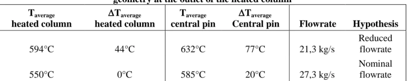
The average sodium temperature at the outlet of the heated column is evaluated for the deformed geometry on Table 1 and compared to the averaged sodium temperature of 550°C, obtained for the nominal geometry. Keeping on the deformed geometry the same flowrate as for the nominal geometry, the increase of temperature is null by energy conservation since the power to be extracted is unchanged, whereas it increases by 44°C for the reduced flowrate. The sodium temperature around the central fuel pin is more largely perturbed since it changes from 565°C for the nominal geometry to 585°C and to 632°C, according to the flowrate. Compared to the nominal situation, it means a temperature increase of 77°C.
Abstract No: Please be sure to fill in the number of the submitted abstract for this full text Paper No.: Table 1. Increase of the average sodium temperature between the nominal and the 6% deformed
geometry at the outlet of the heated column Taverage heated column Taverage heated column Taverage central pin Taverage
Central pin Flowrate Hypothesis
594°C 44°C 632°C 77°C 21,3 kg/s Reduced flowrate 550°C 0°C 585°C 20°C 27,3 kg/s Nominal flowrate
This increase of the average sodium temperature around the central pin is also visualized on Fig. 12. The sodium temperature is represented at the outlet of the heated column as a function of the distance to the center of the sub-assembly, the sodium temperature being averaged on the circumference. This Fig. 12 also highlights that the temperature difference between the center and the periphery of the sub-assembly is increased for the deformed geometry. The temperature difference of 80°C for the nominal geometry reaches 140°C for the geometry deformed and the reduced flowrate.
Fig. 12 Outlet temperature vs radius
3.4 Maximum clad temperature
Mechanical strength of the clad is generaly evaluated at its mid-thickness. The clad temperature at this location is evaluated from the outer clad temperature, the same one as the sodium temperature in contact with it, from the clad thermal conductivity and from the local heat flux by using the Fourier law.
𝑇𝑚𝑖𝑑−𝑡ℎ𝑖𝑐𝑘𝑛𝑒𝑠𝑠= 𝑇𝑐𝑙𝑎𝑑+ 𝜆𝑐𝑙𝑎𝑑𝛷
𝑅𝑚𝑖𝑑−𝑡ℎ𝑖𝑐𝑘𝑛𝑒𝑠𝑠∙ln 𝑅𝑚𝑖𝑑−𝑡ℎ𝑖𝑐𝑘𝑛𝑒𝑠𝑠𝑅𝑜𝑢𝑡𝑒𝑟
(8) 𝑇𝑚𝑖𝑑−𝑡ℎ𝑖𝑐𝑘𝑛𝑒𝑠𝑠 : clad temperature at mid-thickness (°C)
𝑇𝑐𝑙𝑎𝑑 : outer clad temperature (°C) 𝛷 : local thermal heat flux (W/m2
)
𝜆𝑐𝑙𝑎𝑑 : clad thermal conductivity (W/m/K)
𝑅𝑚𝑖𝑑−𝑡ℎ𝑖𝑐𝑘𝑛𝑒𝑠𝑠 : mid-thickness and outer clad radius (m) 𝑅𝑜𝑢𝑡𝑒𝑟 : outer clad radius (m)
Abstract No: Please be sure to fill in the number of the submitted abstract for this full text Paper No.:
Using (8), the clad temperature at mid-thickness is about 20°C higher than the outer clad temperature, assuming that the heat flux is taken at the top of the heated column.
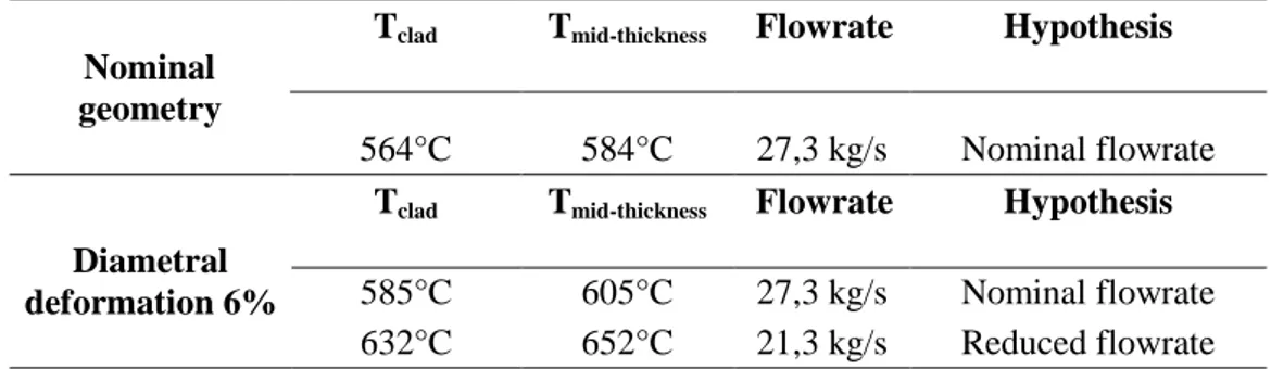
The results obtained for the three calculations are summarized in Table 2. For the nominal geometry, the maximum clad temperature at mid-thickness is around 585°C. It reaches 605°C and 652°C on the deformed geometry, repectively for the nominal and reduced flowrates. The effect of fuel diameter deformation on temperature is therefore significant in reactor conditions.
Table 2. The average clad temperature on the outer side and at mid-thickness
Nominal geometry Tclad Tmid-thickness Flowrate Hypothesis 564°C 584°C 27,3 kg/s Nominal flowrate Diametral deformation 6% Tclad Tmid-thickness Flowrate Hypothesis 585°C 605°C 27,3 kg/s Nominal flowrate 632°C 652°C 21,3 kg/s Reduced flowrate
With the conservative assumptions made in these calculations, the mid-thickness clad temperature reaches 652°C for the deformed geometry and the reduced flowrate. Therefore, the effect of deformation induces a large increase of temperature. These results highlight the advantages of this approach that allows a local evaluation of the temperature field.
It must however be recalled that the conservative hypothesis leads to higher temperatures that are expected in reality. First, the diametral deformation of 6% used for this study is beyond the criterion of the admissible volume deformation. Clad deformation also depends on temperature through clad swelling and creep [13] [14], therefore any temperature increase in the sub-assembly will affect the geometry. This feedback phenomenon coud be evaluated by a coupled modelling between thermal-hydraulics and thermomechanics that would better provide the impact of irradiation on the clad temperature. Uncertainties on the clad temperature will also be investigated in order to be compared to the maximum admissible clad temperature that is 700°C for the current clad material.
Abstract No: Please be sure to fill in the number of the submitted abstract for this full text Paper No.:
4
CONCLUSION AND PROSPECTS
Sensitivity of thermal-hydraulics to the fuel bundle deformation was investigated in this paper. Thanks to a numerical CFD approach, thermal-hydraulics in the sub-assembly was studied for the nominal geometry and a highly deformed one to 6% in pin diameter. Assuming a decrease of flowrate in order to respect the same sub-assembly pressure drop, the radial temperature gradient between the central zone and the periphery of the sub-assembly was found to increase from 80°C to 140°C. The local clad temperature at mid-thickness was also increased from 585°C to 652°C.
This study was conservative. On the one hand, the diametral deformation is twice as high as the maximum admissible value in nominal condition in reactor. On the other hand, this deformation is applied to total heat column of all the pins. In reality, clad swelling and creep are dependent on temperature and irradiation dose. Any perturbation on the clad temperature will therefore affect the sub-assembly swelling, hence the flowrate will also be changed by this deformation, since the core pressure drop is fixed. Given the large temperature perturbation found for the deformed geometry, it is suggested to treat together thermal-hydraulics and thermomechanics in the sub-assembly.
This approach envisaged to study the temperature feedback on the fuel bundle thermomechanics, is already under study [15]. An interface between thermal-hydraulics evaluated in this paper with the STAR-CCM+ code and a thermomechanical code [16] is developed. The final objective is to provide less conservative results on clad temperature that represents on a better way the clad behaviour in reactor. This work will also help to better assess the clad deformation criterion on thermal-hydraulics.
Abstract No: Please be sure to fill in the number of the submitted abstract for this full text Paper No.: NOMENCLATURE
Glossary
ASTRID Advanced Sodium Technological Reactor for Industrial Demonstration
CEA Alternative Energies and Atomic Energy Commission (Commissariat à l’Energie
Atomique et aux Energies Alternatives)
CFD Computational Fluid Dynamics
FG Fission gas
def Deformed geometry
non def Non-deformed geometry
RANS Reynolds Averaged Navier-Stokes
SFR Sodium-cooled Fast Reactor
Abbreviations
A Cross-section of the fuel bundle (m2)
Dclad Clad diameter (m)
Dwire Spacer wire diameter (m)
Dh Hydraulic diameter (m)
gap Distance between the pin of the last row of the sub-assembly to the wrapper tube
f Friction factor (-)
L Height of the fuel bundle (m)
p Pitch of the fuel pin (m)
Q Flow rate in the sub-assembly (kg/s)
Re Reynolds number (-)
Rmid-thickness Clad radius at its mid-thickness (m) Router External clad radius (m)
Tclad Outer clad temperature (°C)
Tmid-thickness Clad temperature at mid thickness(°C)
Coefficient relative to the pressure loss in the sub-assembly, except the fuel bundle (-)
ΔP Pressure drop in the sub-assembly (Pa)
ΔPbundle Pressure drop in the fuel bundle (Pa)
y+ Dimensionless distance from the wall
λclad Clad thermal conductivity (W/m/K)
ρ Sodium density (kg/m3)
k Turbulent kinetic energy (J/kg)
ε Turbulent kinetic energy dissipation rate (J/kg/s)
𝛷 Local thermal heat flux (W/m2)
REFERENCES
1. CD Adapco, STAR-CCM+ User Guide Version 9.02
2. P. Le Coz et al. “Sodium-Cooled Fast Reactors: the ASTRID Plant Project“. Proceedings o f ICAPP 2011, Nice, France, May 2-5, 2011. Paper 11249.
3. G.S. Was,“Fundamentals of radiation materials science, Metals and alloys”, Springer Berlin, Heidelberg. 2007.
4. N. Schmidt, “Endommagement de la gaine des éléments combustibles du réacteur à neutron s rapides PHENIX. Réalisation et analyse d’expériences de chargement limite. Validation et optimisation de la méthodologie de dimensionnement RAMSES 2 “, Thèse CNAM 1992.
Abstract No: Please be sure to fill in the number of the submitted abstract for this full text Paper No.:
5. E. Baglietto et al. “A quantitative CFD benchmark for Sodium Fast Reactor fuel assembly modeling”. Massachusetts Institute of Technology, United States, Annals of Nuclear Energ y 64(2014), 32-42.
6. W.D Pointer et al. “RANS-based CFD simulations of sodium fast reactor wire-wrapped pin bundles. American Nuclear Society – International Conference on Mathematics. Computatio nal Methods and Reactor Physics 2009, M and C 2009, Volume 4, pp 2212-2224, 2009. 7. K.D. Hamman et all. “A CFD simulation process for fast reactor fuel assemblies” Idaho N
ational Laboratory, P.O. Box 1625, Idaho Falls, ID 83415-3840, USA, Nuclear Engineering and Design 240 (2010) 2304-2312, 2010.
8. P. Petiot, J.M Seiler. “Physical properties of sodium : a contribution to the estimation of cr itical coordinates”. High Temperature and High Pressure 1984, Vol.16 p 289-293.
9. Smith et all. “Predictions in CFD simulations of wire-wrapped SFR fuel assemblies”. 2009, Tokyo, Japan, ICAPP 09.
10. S.K. Chen, N.E Todreas and N.T Nguyen, “Evaluation of existing correlations for the pred iction of pressure drop in wire-wrapped hexagonal array pin bundles”. Nuclear Engineering and Design, vol 267, p109-131, 2014.
11. N.E. Todreas and K.S. Mujid, Nuclear Systems II : Elements of thermal hydraulic design. New York, Hemisphere Pub. Corp, 1990.
12. E. Bubelis, M. Schikorr. Review and proposal for best fit of wire-wrapped fuel bundle fri ction factor and pressure drop predictions using various existing correlations. Nuclear Engi neering and Design 238 (2008) 3299-3320.
13. M.P. Surth, J.B Sturgeon, W.G Wolfer, “Radiation swelling behavior and its dependence on temperature, dose rate, and dislocation structure evolution, “Journal of Nuclear Materials, vol 336,p 217-224, 2004.
14. M. Le Flem et al., “French R&D on materials for the core components of Sodium Fast R eactors”, IAEA-CN-199/215, 2013.
15. F. Acosta et al, “Evaluation of thermal-hydraulics and thermomechanics coupling strategies for the modeling of the performance of fuel assemblies of Sodium-cooled Fast Reactors under irradiation”. NUTHOS 2018.
16. G. Gaillard-Groleas, “New simulation tools to be developed for the ASTRID program”. Technical meeting AIEA 14-16 April 2014.