Comparison of high level design methodologies for
algorithmic IPs : Bluespec and C-based synthesis
by
Abhinav Agarwal
Submitted to the Department of Electrical Engineering and Computer
Science
in partial fulfillment of the requirements for the degree of
Master of Science in Electrical Engineering and Computer Science
at the
MASSACHUSETTS INSTITUTE OF TECHNOLOGY
February 2009
@
Massachusetts Institute of Technology 2009. All rights reserved.
Author ...
Department of Electrical Engineering and Computer Science
(N
Feb 1 2009
Certified by ...
Arvind
Professor
Thesis Supervisor
Accepted by ...
Terry P. Orlando
Chairman, Department Committee on Graduate Students
ARCHIVES
MASSACHUSETTS INSTITlrE
OF TECw AL>OLOy
MAR 0 5 20R9
L
'P
,
R ES
Comparison of high level design methodologies for
algorithmic IPs : Bluespec and C-based synthesis
by
Abhinav Agarwal
Submitted to the Department of Electrical Engineering and Computer Science on Feb 1, 2009, in partial fulfillment of the
requirements for the degree of
Master of Science in Electrical Engineering and Computer Science
Abstract
High level hardware design of Digital Signal Processing algorithms is an important design problem for decreasing design time and allowing more algorithmic exploration. Bluespec is a Hardware Design Language (HDL) that allows designers to express in-tended microarchitecture through high-level constructs. C-based design tools directly generate hardware from algorithms expressed in C/C++. This research compares these two design methodologies in developing hardware for Reed-Solomon decoding algorithm under area and performance metrics.
This work illustrates that C-based design flow may be effective in early stages of the design development for fast prototyping. However, the Bluespec design flow produces hardware that is more customized for performance and resource constraints. This is because in later stages, designers need to have close control over the hardware structure generated that is a part of HDLs like Bluespec, but is difficult to express under the constraints of sequential C semantics.
Thesis Supervisor: Arvind Title: Professor
Acknowledgments
I would like to express my deep and sincere gratitude to my advisor, Professor Arvind. This work has been possible because of his encouragement and guidance provided to me in the course of this project.
I wish to extend my warmest thanks to Alfred Ng and S.R.K. Branavan, who collab-orated with me during this work. I am grateful to Dr. Jamey Hicks and Dr. Gopal Raghavan for their assistance in using resources provided by Nokia Research Center at Cambridge. All the members of the ARMO group and the CSG-Arvind group have been a great source of advice and support, and I would like to thank them for it.
Contents
1 Introduction
1.1 C-based design tools ...
1.2 Bluespec ... .. ... 1.3 Design process ... ... 1.4 Thesis Outline ... ... 2 The Application: Reed-Solomon Decoder
2.1 Decoding Process and its Complexity . . . 2.2 Algorithms and Pseudocode ...
2.2.1 Galois Field Arithmetic . . . . 2.2.2 Syndrome Computation . . . . 2.2.3 Berlekamp-Massey Algorithm . . . 2.2.4 Chien Search ...
2.2.5 Forney's Algorithm ...
2.2.6 Error Correction . . . ...
3 Hardware Implementation using C-based design flow 3.1 Defining Module Interfaces . ... ... 3.2 Initial Implementation in Catapult-C . ... ...
3.2.1 Loop Unrolling . . . ...
3.3 Language-related issues with refinements . . . . .. 3.3.1 Problems with Streaming under Dynamic Conditions 3.3.2 Substantial Source Code Modifications . . . ..
8 . . .. .. .. . . . 9 . . . . 10 . . . . . 10 . . . . 12 13 . . . . 14 . . . . . 15 . . . . 15 . . . . 16 . . . . 17 . . . . . . 18 . . . . . . 18 ... . . . . 19 20 20 22 22 23 23 25
4 Hardware Implementation using Bluespec 4.1 Initial Implementation in Bluespec .... 4.2 Refinements made in Bluespec Design . . .
4.2.1 Manual Unrolling . ... 4.2.2 Out-of-order Execution . . . . 4.2.3 Pipelining . ... 4.2.4 Buffer Sizing . . . ... design flow . . . .
5 Results and Performance Analysis
5.1 Source code size ... .. ... ... 5.2 Hardware synthesis results . . . . . . . . . .. 5.3 Performance analysis ... .. . . ... 6 Conclusion Bibliography 27 28 29 30 31 32 33 34 34 34 35 36 37
List of Figures
2-1 Stages in Reed-Solomon decoding ... 3-1 3-2 3-3 3-4 3-5 4-1 4-2 4-3 4-4 4-5 4-6
Top level function...
Simple streaming example - source code . . Simple streaming example - hardware output . Complex streaming example -source code . . . Complex streaming example - hardware output Bluespec interface for the decoder . ... Initial version of syndrome module ...
Parameterized parallel version of the compute-syndrome rule . Statically elaborated code generated by Bluespec ...
The original structure of the Forney's Algorithm Implementation . The modified structure of the Forney's Algorithm Implementation
. . . . 21
. . . . . 24
. . . . . 24
. . . . . 25
List of Tables
2.1 Order of GF Arithmetic Operations ... ... 14
2.2 Input and output symbols per step . ... 15
3.1 Performance impact of unrolling ... . ... .. . 23
4.1 Performance impact of Buffer size . ... . 33
5.1 FPGA synthesis summary ... .. ... 35
Chapter 1
Introduction
A wide range of DSP applications require large amounts of computations at reason-able power budgets. To satisfy these requirements, many DSP algorithms are imple-mented in dedicated hardware. Meanwhile, DSP algorithms are often modeled using MATLAB or C/C++ because of the familiarity of algorithm designers with these lan-guages and because it frees the designers from hardware considerations. A tool that could generate efficient hardware directly from these high-level codes would be ideal for implementers. Such a tool, however, must provide its users with mechanisms to control generated hardware so that implementations with different performance, area and power tradeoffs can be generated according to the usage of the DSP algorithm. Several EDA vendors provide tools for this purpose [1, 2, 3, 4].
There are reasons to be optimistic about such C-based tools. DSP algorithms are usually highly structured and have abundant fine-grained parallelism. This is exactly the kind of parallelism where extensive research in parallel compilers over the last three or four decades has shown the greatest success. Since hardware generation is mostly about exploiting fine-grained parallelism, the rich body of compiler research should be directly applicable to the task at hand. The practical question is whether the compiler or the tool can be directed to generate hardware that satisfies some specific area, performance or power metric. Even if ASIC implementation is not the final target, the ability to direct the tool to generate a design within the resource constraints of a specific FPGA is an important question. The economic importance
of this question is obvious: if C-based synthesis cannot lead to the ultimate target design then at some stage, the implementers will have to jump the rail at enormous design cost and resort to RTL design and synthesis tools.
1.1
C-based design tools
C-based tools fall into two distinct categories - those that adhere to pure C/C++ semantics like Catapult-C [2], Synfora [4], etc. and those that deviate from the pure semantics by allowing new constructs, like HandelC [1], SystemC [5], etc. The external constructs are introduced to aid in expressing parallelism. But the issue then arises that once a designer is willing to give up on the pure sequential C semantics, the main benefit of using C-based design flow is already lost. For our study, we chose a tool that maintains C semantics but allows external annotations and settings for greater customization.
Catapult-C, a high-level synthesis tool developed by Mentor Graphics for hard-ware synthesis from ANSI-standard C/C++, is a good example of a tool to explore this domain. It provides mechanisms to control the generated hardware. General constraints, such as the operating frequency, can be applied to the whole design. The tool automatically explores the design space to find a design that satisfies the constraints. The user can give annotations, for mechanisms such as loop unrolling, regarding how to optimize a particular part of the program without affecting the cor-rectness of the code. Hardware designers perceive several advantages in using such a C-based design methodology [6, 7] - having a concise source code allows faster de-sign and simulation, technology-dependent physical dede-sign is relatively isolated from the source and using an untimed design description allows high level exploration by raising the level of abstraction. Using Catapult-C, Guo et al. [8] were able to rapidly prototype components used in 4G Wireless systems for FPGA implementation.
1.2
Bluespec
Most implementers of DSP algorithms regard designing at the RTL level (as in Verilog or VHDL) as tedious, inflexible, error-prone and slow. The high costs of ASIC and FPGA designs give credence to this belief. Bluespec [9] is a synthesis tool to help the designer express both the structure and the behavior of the desired micro-architecture at a higher abstraction level. Bluespec SystemVerilog (BSV), the input language for the tool, is built on sound ideas from modern functional and object-oriented program-ming languages, and uses guarded atomic actions to express concurrent behaviors succinctly [10, 11]. Bluespec facilitates latency insensitive designs by automatically generating handshaking signals between components. This allows designers to incre-mentally refine modules to meet their requirements. For example, in [12], Dave et. al. describe the design of an 802.11a transmitter using the Bluespec design methodology. From the same parameterized source code they were able to generate many different designs for the IFFT block, which consumed the majority of resources, to obtain an optimal design for the 802.11a transmitter. Similar experiences are reported for many other designs in Bluespec, e.g., reusable blocks for OFDM protocols [13], H.264 decoder [14], out-of-order processors [15], cache coherence protocol processors [16]. However, the Bluespec tool, unlike Catapult-C, does not do any design exploration on its own - it only facilitates the expression of different design alternatives.
1.3
Design process
In this work the two design methodologies are compared via the implementation of a Reed-Solomon decoder. This example was chosen because it represented a non-trivial algorithmic IP but is simpler than an H.264 decoder. We were not familiar with Reed-Solomon codes before we started this project and needed a Reed-Solomon decoder to implement an 802.16 WiMAX protocol receiver [17]. We expected that it would be straightforward to express the desired decoder for the target performance in Bluespec. Indeed that turned out to be the case. However, even to understand what
a Reed-Solomon decoder does we ended up writing it in C++ first. We used this code as a golden model for the verification of the Bluespec code. We were also curious to evaluate the hardware generated from our C++ code by C-based synthesis and for this purpose we picked Catapult-C. With straightforward modifications to the C++ source code, and Catapult-C provided annotations, we were successful in quickly generating hardware but it achieved about 7% of the target throughput. However, even with considerable effort we were only able to improve the design throughput to 64% of the target. The initial Bluespec design could achieve 17% of the target throughput and with modular refinements, the design's throughput improved to 504% of the target throughput, while it still used only 45% equivalent FPGA gate count as compared to the final Catapult-C design. As a point of comparison, we compared our designs with a reference Xilinx IP core and found that the Bluespec design achieves 178% of the Xilinx IP's data rate with 90% of the equivalent gate count.
This work started as a project in the Complex Digital Systems (6.375) course, done in collaboration with S.R.K. Branavan. The course project produced the initial design done in Bluespec. Later, the work was expanded to be used as a design example for a hardware design methodology comparison. During the design process, some of the design refinements were done in collaboration with Alfred Ng.
The main contribution of this work is to illustrate some of the issues that need to be solved for C-based synthesis to generate competitive hardware for algorithmic IP blocks. Unless designers can express important design properties (e.g., the structuring of state elements, the pipelining of inter-module communication, and the fine-grained resource arbitration), C-based synthesis will be of limited use in final ASIC or FPGA implementations. We believe that expressing this information while simultaneously complying with sequential C semantics is very difficult. Furthermore, this study illustrates that designers can express these properties naturally in high-level HDLs like Bluespec, while maintaining the inherent algorithmic modularity.
1.4
Thesis Outline
Chapter 2 describes Reed-Solomon decoding algorithm. The fundamental arithmetic operations used, as well as the pseudocode used in the implementation are also shown. Chapter 3 describes the hardware implementation of the decoder using the C-based design flow. Design refinements and complexities introduced due to semantic restric-tions are also discussed.
We discuss the design implementation using Bluespec design flow in Chapter 4. The modular refinements made possible by Bluespec design flow are described. In Chapter 5, we compare the final designs produced using performance and synthesis metrics. Finally, the thesis concludes with Chapter 6, which provides a summary of the re-search.
Chapter 2
The Application: Reed-Solomon
Decoder
Reed-Solomon codes [18] are a class of error correction codes frequently used in wire-less protocols like 802.16 [17]. In this work, we designed a Reed-Solomon decoder for use in an 802.16 protocol receiver. The decoder accepts a primitive polynomial in Galois Field 28 as a static variable, and the number of information and parity sym-bols as dynamic variables. To simplify the design, our current design only supports shortened and full-length codes, and not punctured codes.
We chose the minimum throughput requirement of the design to be 134.4 Mbps, which is the maximum data rate supported by the 802.16 protocol. With the chosen decoding algorithm, 81K arithmetic operations (Bitwise XORs) are needed to process a 255 byte input data block. We used the Xilinx Reed-Solomon decoder IP version 5.1 as a baseline reference, which operates at a frequency of 145.3 MHz and can ac-cept a new 255 byte input data block every 660 clock cycles for a data throughput of 392.8 Mbps. The target operating frequency for our Bluespec and C-based designs was kept at 100 MHz. To achieve the 802.16 protocol requirement at this frequency, the designs need to accept a new input block every 1520 cycles. To match the Xilinx IP's throughput at 100 MHz, the throughput requirement becomes 520 cycles per input block. There is some advantage in overshooting the minimum performance re-quirement because the "extra performance" can be used to lower voltage or operating
frequency for low power implementations. However, in this study we have not pursued the low power issues beyond aiming for high performance. During the design process, our goal was to reduce the number of cycles taken to process a block by increasing parallelism and to improve throughput by pipelining.
2.1
Decoding Process and its Complexity
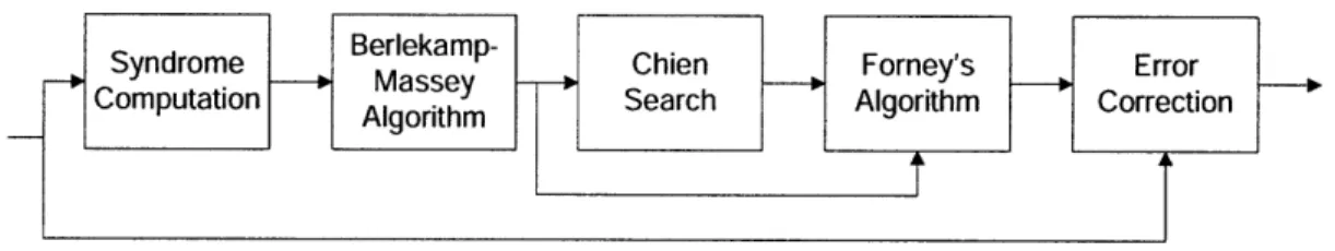
Reed-Solomon decoding algorithm [19] consists of 5 main steps shown in Figure 2-1. Each input block is decoded independently of other blocks. A detailed description of each step along with pseudocodes has been shown in Section 2.2.
Berlekamp-Syndrome Chien Forney's Error
Computation Algorithm Algorithm Search Algorithm Correction
Figure 2-1: Stages in Reed-Solomon decoding
A Reed-Solomon encoded data block consists of k information symbols and 2t par-ity symbols for a total of n(= k + 2t) symbols. The decoding process is able to correct a maximum of t errors. Table 2.1 shows the order of associated Galois Field (GF) arithmetic operations - addition, multiplication by a constant and multiplication by a variable.
Step GF Add Const GF Mult Var GF Mult
Syndrome O(trn) O(tn) 0
Berlekamp O(t2) 0 O(t2)
Chien O(tn) O(tn) 0
Forney O(t2) O(t2) 0(t)
Correction O(t) 0 0
Table 2.1: Order of GF Arithmetic Operations
Since this is a streaming application, the inter module communication has a signif-icant impact on performance. An additional complexity arises due to the difference in the Input-Output data block sizes for each step. For an input block of size n symbols,
with 2t parity symbols and v errors, Table 2.2 shows the number of input and output symbols for each block. The values in Tables 2.1 and 2.2 have been derived from the algorithm described in the next section. Readers familiar with the algorithm can skip ahead to Chapter 3.
Step Input Symbols Output Symbols
Syndrome n 2t
Berlekamp 2t 2v
Chien v v
Forney 3v v
Correction 2(n - 2t) (n - 2t)
Table 2.2: Input and output symbols per step
2.2
Algorithms and Pseudocode
An important step in the design is the translation of the mathematical algorithm into high level pseudocode. This translation is commonly done in C/C++ or MATLAB code. In the following discussion of the Reed-Solomon decoding algorithm, the input data block is denoted as
R(x) = rx n - 1 + rn-2xn - 2 + ... + r (2.1)
where the parity symbols are r2t-1, r2t-2, ... , ro. This polynomial representation is used in arithmetic involving data blocks, with the index x representing the position of a symbol with the data block.
2.2.1
Galois Field Arithmetic
Galois Fields are finite fields described by a unique primitive polynomial pp, with root ca. For Reed-Solomon codes defined over GF 2', each data symbol can be de-scribed by an 8 bit value mapped to a finite field element. Every encoded data block consists of upto 28 - 1 data symbols. In algorithms described in this section, all arithmetic is done using GF 28 arithmetic byte operators which are defined as follows:
GF Add: It is equivalent to a bitwise XOR operation of the data symbols, denoted by e.
GF Mult: This is multiplication modulo operation over the primitive polynomial pp, denoted by 0. Using an iterative process, multiplying by a variable takes 15 bitwise XOR operations. Multiplication by a constant only takes at most 8 XOR operations, depending on the constant.
GF Divide: Division is a complex operation. It is commonly performed by mul-tiplying the dividend and the inverse of the divisor, found via a lookup table. This operator is denoted by 0.
2.2.2
Syndrome Computation
In this step the received polynomial, comprising of n data symbols, is used to compute 2t symbols known as the Syndrome polynomial using the following expression:
Si = rn_1a(n-1)j + n-2 (n- 2)j + ... 0 Vj E 1..2t (2.2) Pseudocode: Input: ro, 1, .. , rn-1 Output: S1, S2, ... , S2t Initialize: Sj = 0, Vj E 1..2t for i=n- 1 to 0 for j = 1 to 2t Sj = ri
E
Sj a2.2.3
Berlekamp-Massey Algorithm
Berlekamp-Massey Algorithm computes an error locator polynomial A(x) of degree v and an error evaluator polynomial Q(x) of degree v for a received input vector with v errors. A(x) and Q(x) are computed from S(x) using the following relations:
SJ = ZAiS-i Vj E v+1,...,2v (2.3) i=1 Q(x) = S(x) x A(x)(modx 2t) (2.4) Pseudocode: Input: S1, S2, ... , S2t Output: A1, A2, ... , A ; 1, 2, . - - , Qv
Initialize: L = 0, A(x) = 1, Aprev(X) = 1,
Q(x) = O, Qprev(x) = 1, I1 = 1, dm = 1 for j = 1 to 2t d = Sj E EiE{1..L} Ai 0 Sj-i if (d=0) 1=1+1 else if (2L > j)
A(x) = A(x) e {d 0 d dm} 0 Aprev(X)
Q(x) = Q(x) e {d 0 dm}xl t 0 prev(X) 1 =1+1 else swap(A(x), Aprev(x)) swap (Q(x), Qprev(x))
A(x) = Aprev(x) D {d 0 dm}xl 0 A(x)
Q(x) = Qprev(X) e {d 0 dm}x1 0 Q(x)
2.2.4
Chien Search
The error locations are given by the inverse roots of A(x), which can be computed using the Chien search algorithm. Error Locations locj are given by the following relation:
A(a -locj) = 0 (2.5)
Pseudocode:
Input: A, A2,...,Av
Output: loci,loc2,. . . , loc for i= 0 to n
Sum = 0
for k = 0 to v
Sum = Sum e Aka - ik
if (Sum = 0)
loci = i
j=j+1
2.2.5
Forney's Algorithm
Using A(x) and Q(x), the error values are computed at the error locations. At all other indices the error values are zero. The magnitudes are found by Forney's algorithm which gives the following relation:
o = A'(a-l"oc ) (2.6) Pseudocode:
Input: AI,...,A,;
Output: eloci, ... , eloc,
for i = 1 to v for j = 0 to v
SumQ = Sumn D Qja - locj
for j = 0 to L
SumA = SumA E A2j-1 a - locij
eloci = Sumn 0 SumA
2.2.6
Error Correction
The error locations and values obtained in previous steps are used in the correction of the received polynomial to produce the decoded polynomial.
d(x) = r(x) - e(x) (2.7)
Pseudocode:
Input: rn-1 rn-2, - -k-1; en-, en-2, ... , ein-k-1
Output: dn-1, dn-2, .. dn-k-1
for i=n-1 to n-k-1
di = ri D ei
It is straightforward to translate this pseudocode into actual code in almost any high level language.
Chapter 3
Hardware Implementation using
C-based design flow
In this project, we first implemented the pseudocode presented in Section 2.2 in C++. This provided a golden functional model as well as solidified our understanding of the algorithm. After we had a working reference implementation, we used the following approach to generate a hardware implementation of the design in Catapult-C.
3.1
Defining Module Interfaces
We first define the top level architecture of the hardware design, which describes the module partitioning and the inter-module communications.
Each hardware module can be declared as a function that takes inputs and gives outputs using pointers. A hierarchy of modules can be formed by writing a func-tion which calls other funcfunc-tions. Data communicafunc-tion between modules in the same hierarchy is automatically inferred by the Catapult-C compiler by data dependency analysis. Without modifying the function declarations, Catapult-C allows system designers to explicitly specify the widths and the implementation types of data com-munication channels. The available implementation types include wires, First In First Out buffers (FIFOs) or Random Access Memory buffers (RAMs).
well known compilation techniques to exploit parallelism. For example, it can exploit the data parallelism within the function by loop unrolling and data flow analysis. It can also exploit pipelining across consecutive calls of the same function through software pipelining and parallel executions of modules in the same hierarchy. While these techniques are efficient to some extent, they have their limitations. For example, loop unrolling and software pipelining are only applicable to loops with statically determined number of iterations. The transaction granularity on which the function operates is a tradeoff between performance and implementation effort. Coarse-grained interface, in which each function call processes a large block of data, allows system designers to naturally implement the algorithm in a fashion similar to software. On the other hand, grained interface allows the Catapult-C compiler to exploit fine-grained parallelism existing in the algorithm at the expense of higher implementation effort. Similar observations about these two styles are mentioned in [7], where coarse-grained functions are referred to as block mode processing and fine-coarse-grained functions as throughput mode processing.
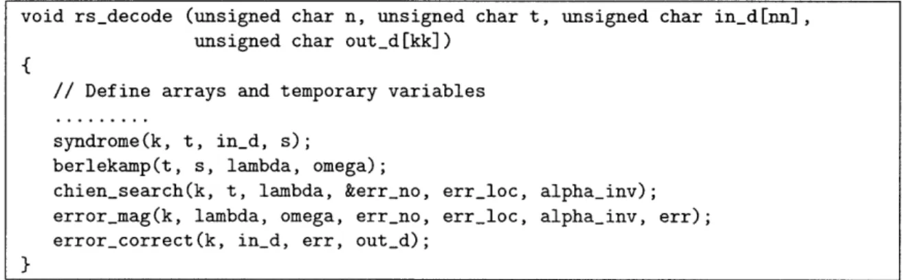
In our design, we represent each stage of the Reed-Solomon decoder as a separate function. This naturally translates into block mode processing with coarse grained interfaces between modules. Making the interfaces fine-grained would have greatly increased code complexity as discussed in Section 3.3 and reduced the modular nature of the design. The highest level function invokes these functions sequentially as shown in code segment in Figure 3-1.
void rs_decode (unsigned char n, unsigned char t, unsigned char in_d[nn], unsigned char out_d[kk])
{
// Define arrays and temporary variables
syndrome(k, t, ind, s);
berlekamp(t, s, lambda, omega);
chien_search(k, t, lambda, &err_no, errloc, alphainv); error_mag(k, lambda, omega, err_no, err_loc, alphainv, err); error_correct(k, in_d, err, outd);
In the function arguments, nn and kk refer to the maximum allowed values of the dynamic parameters n and k respectively.
3.2
Initial Implementation in Catapult-C
Catapult-C emphasizes the use of for-loops to express repeated computations within a module [20]. To expose parallelism it provides the user with knobs to determine loop unrolling or loop pipelining. As previously discussed in Section 2.2, each of the major computational steps of Reed-Solomon decoding have this structure. Thus we expect Catapult-C to be very effective at providing a direct implementation of the decoding steps in terms of modules, each having for-loops of different lengths. Since
Catapult-C has the ability to compile native C/C++ program, obtaining the initial synthesized design is trivial. The compiler automatically designs the Finite State Machines (FSMs) associated with each module. The pseudocode described in Sec-tion 2.2 was modified to the C++ subset accepted by Catapult-C. Memory allocaSec-tion and deallocation is not supported and pointers have to be statically determined [20]. The for-loops were kept as described in the pseudocode; no loop unrolling was per-formed. The resulting hardware took on 7.565 million cycles per input block, for the worst case error scenario. The high cycle count in the C-based implementation was due to Catapult-C generating a highly sequential implementation. To improve the throughput, we made use of the techniques offered by Catapult-C.
3.2.1
Loop Unrolling
Catapult-C compiler can automatically identify loops that can be unrolled. By adding annotations to the source code, the user can specify which of these identified loops need to be unrolled and how many times they will be unrolled. As a first step we unrolled the loops corresponding to the GF Multiplication (Section 2.2.1), which is used multiple times throughout the design. Next, the inner for-loop of Syndrome computation (Section 2.2.2) was unrolled to parallelize the block. The inner for-loop of the Chien search (Section 2.2.4) was also unrolled. To perform these steps we had
to replace the dynamic parameters n and k by static upper bounds. Combining these unrolling steps lead to a significant improvement in the throughput, achieving 19020 cycles per input block, as shown in Table 3.1. This cycle count was equivalent to 7% of the target data throughput.
Unrolled functions Throughput (Cycles/Block)
None 7565K
GF Mult 237K
GF Mult, Syndrome 33K
GF Mult, Syndrome, Chien 19K
Table 3.1: Performance impact of unrolling
The unrolling steps lead to some simplification of the complex FSMs initially generated at the cost of increased hardware for arithmetic operations per module.
3.3
Language-related issues with refinements
To further improve the performance, we needed to achieve further pipelining of some blocks. This section describes some of the issues that arose due to adherence of C semantics, when we attempted to make some complex refinements. For improving throughput, the decoder modules need to be able to stream inputs and outputs ef-ficiently. However, representing this requirement is unnatural in Catapult-C due to presence of for-loops with dynamic lengths, in the design. This makes the task of generating the inter-module buffers quite tedious.
3.3.1
Problems with Streaming under Dynamic Conditions
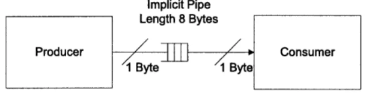
In Catapult-C separate modules (represented as different functions) share data using array pointers passed as arguments. For simple streaming applications, the compiler can infer that both the producer and consumer operate on data symbols in-order and can generate streaming hardware as expected by the designer. To illustrate how this happens more clearly, consider the code segment shown in Figure 3-2. In this
example, the producer function writes to intermediate array one element at a time every cycle, and the consumer function reads from it at the same rate.
Figure 3-2: Simple streaming example - source code
The Catapult-C compiler correctly infers that these functions can be executed in an overlapping fashion while they are operating on the same array. It generates streaming hardware in the form shown in Figure 3-3. Here the compiler infers that a basic pipe with a length of 8 bytes was sufficient for communicating between the modules.
Implicit Pipe Length 8 Bytes
Figure 3-3: Simple streaming example - hardware output
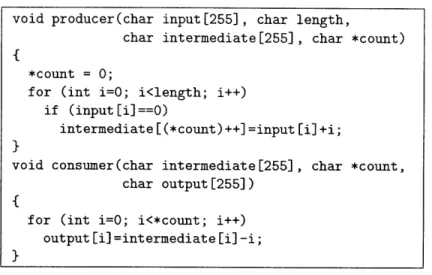
However, the presence of dynamic parameters in for-loop bounds can obfuscate the sharing of streamed data. If the data block is conditionally accessed, these dynamic conditions prevent the compiler from inferring streaming architecture. For example, consider the code segment shown in Figure 3-4, where the producer dynamically determines the data length on which to operate and produces values sporadically.
This results in the hardware shown in Figure 3-5. The compiler generates a large RAM for sharing one instance of the intermediate array between the modules. To
void producer(char input[255] ,
char intermediate [255])
{
for (int i=O; i<255; i++)
intermediate [i] =input [i] +i;
}
void consumer(char intermediate[255] , char output[255])
{
for (int i=O; i<255; i++)
output [i]=intermediate [i]-i;
Figure 3-4: Complex streaming example - source code
ensure the program semantics, the two modules will not be able to simultaneously access the array, which prevents overlapping of execution of the two modules.
Length 8 Bytes
Figure 3-5: Complex streaming example - hardware output
Catapult-C provides an alternative buffer [20] called ping-pong memory which uses a double buffering technique, to allow some overlapping execution, but at the cost of using twice the memory size. Using this buffer, our design's throughput improved to 16,638 cycles per data block. The cycle count was still quite large due to the complex loops in Berlekamp module.
3.3.2
Substantial Source Code Modifications
For further improving the performance and synthesis results, we made use of common guidelines [6] for code refinement. Adding hierarchy to Berlekamp computations and making some of its complex loops static by removing the dynamic variables from the
void producer(char input[255], char length,
char intermediate[255], char *count)
*count = 0;
for (int i=O; i<length; i++) if (input[il==0)
intermediate [(*count)++] =input [i]+i;
void consumer(char intermediate[255], char *count, char output [255])
{
for (int i=O; i<*count; i++) output [i]=intermediate [i]-i;
loop bounds, required algorithmic modifications to ensure data consistency. By do-ing so, we could unroll the Berlekamp module to obtain a throughput of 2073 cycles per block, which was close to the minimum requirement. However, as seen in Sec-tion 5.2, the synthesized hardware required considerably more FPGA resources than the other designs. Further optimizations would require expressing module functions in a fine-grained manner, i.e. operating on a symbol-by-symbol basis. This leads to considerable complexity as hierarchically higher modules have to keep track of individual symbol accesses within a block. The modular design would need to be flat-tened completely, so that a global FSM can be made aware of fine-grained parallelism across the design. Due to this increased code complexity, the abstraction provided by a sequential high level language is broken. Moreover, it is difficult for algorithm designers to express the inherent structure associated with such designs in C/C++. Other publications in this domain have expressed similar views [21]. While we are not experts in the use of Catapult-C, it is evident that certain desirable hardware structures are very hard to describe using C semantics. This forms the basis for the inefficiency in generated hardware which we encountered during our study.
Chapter 4
Hardware Implementation using
Bluespec design flow
As a hardware description language, Bluespec inherently has the concept of mod-ules. A module can communicate with external logic only through methods. Unlike Verilog/VHDL ports which are wires, Bluespec methods are semantically similar to methods in object oriented programming languages, except that they also include as-sociated ready/enable handshake signals. This facilitates implementation of latency insensitive modules. A module interface is declared separately from its implementa-tion. Since Bluespec supports polymorphism, a polymorphic interface can be used to control the communication channel width. However, this requires the implementation of the module to also be polymorphic, which in general increases the implementation effort.
The high-level dataflow of the Reed-Solomon decoding algorithm can be imple-mented using FIFOs to achieve a latency insensitive pipeline as shown in Figure 4-1. Each module's interface simply consists of methods to enqueue and dequeue data with underlying Bluespec semantics taking care of full and empty FIFOs. This inter-face can be further parameterized by the number of the elements to be processed in parallel. This parameterization requires some programming effort but no hardware penalty as the compiler eliminates any excess hardware before producing the RTL.
Figure 4-1: Bluespec interface for the decoder
4.1
Initial Implementation in Bluespec
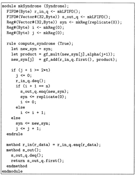
We generated an initial implementation of the decoder by manually translating each for-loop into a simple FSM where each cycle executes a single loop body. The control signals are generated by the compiler automatically. The code shown in Figure 4-2 illustrates how the pseudocode of Syndrome Computation given in Section 2.2.2 was translated into a Bluespec module.
The input and output of the module are buffered by two FIFOs, r_in_q and souLt_q. These FIFOs are one-element Bluespec library FIFOs (mkLFIFO) which allow con-current enqueue and dequeue. We also instantiated three registers: syn, i and j. syn stores the temporary values of the syndrome. The last two are used for loop book-keeping. The entire FSM is represented by a single rule called computesyndrome in the module. This rule models the semantics of the two nested for-loops pre-sented in Section 2.2.2. As long as the input FIFO r_in_q is not empty, the rule gets fired repeatedly until the output is produced. The first three statements of the rule
compute_syndrome correspond to the loop body computation that appeared in the
pseudocode. The remaining code describes how the registers and FIFOs are updated with the appropriate computation results and bookkeeping values. The GF arith-metic operations, gf_mult and gfadd, are implemented as library functions which are compiled into combinational logic.
We implemented each of the five modules using this approach. For t = 16 (32 parity bytes), we obtained a throughput of 8161 cycles per data block, i.e. the decoder could accept a new incoming data block every 8161 cycles. This is 17% of the target data throughput. It should be noted that even in this early implementation, computations in different modules already overlap due to the FIFOs' decoupling.
Figure 4-2: Initial version of syndrome module
4.2
Refinements made in Bluespec Design
After the initial implementation, our next step was to make incremental refinements to the design to improve the performance in terms of reducing the number of cycles taken to process one input block.
Bluespec allows modular refinement, which ensures that each module can be mod-ified independently, while preserving the overall structure of the design.
Assuming the input data stream is available at the rate of one byte per cycle, for the best performance the decoder hardware should accept one input byte per clock cycle giving a throughput close to 255 cycles per input block. In the next few
module mkSyndrome (Syndrome); FIFO#(Byte) r_in_q <- mkLFIFO();
FIFO#(Vector#(32,Byte)) s_out_q <- mkLFIFO(); Reg#(Vector#(32,Byte)) syn <- mkReg(replicate(O));
Reg#(Byte) i <- mkReg(0);
Reg#(Byte) j <- mkReg(0);
rule compute_syndrome (True); let new_syn = syn;
let product = gf_mult(new_syn[j] ,alpha(j+1));
new_syn[j] = gf_add(r_in_q.first(), product);
if (j + 1 >= 2*t) j <= 0; r_in_q.deq(); if (i + 1 == n) s_out_q.enq(new_syn); syn <= replicate(0O); i <= 0; else i <= i + 1; else syn <= new_syn; j <= j + 1; endrule
method r_in(r_data) = r_in_q.enq(r_data); method s_out();
s_outq.deq();
return s_out_q.first();
endmethod endmodule
paragraphs, we describe what refinements are needed to achieve this and how the Bluespec code needed to be modified.
4.2.1
Manual Unrolling
Unlike Catapult-C, Bluespec requires users to explicitly express the level of paral-lelism they want to achieve. That means source code modification may be needed for different implementations of the same algorithm. However, the transformations usually do not require substantial change of the source code. In some occasions, user may even be able to use static parameterization to model the general transformations such as loop unrolling.
We illustrate this using the Syndrome Computation module. This module requires 2t GF Mults and 2t GF Adds per input symbol, which can be performed in parallel. Our initial implementation, shown in Figure 4-2, only performed one multiplication and one addition per cycle. By modifying the rule as shown in Figure 4-3, the module can complete par times the number of operations per cycle.
Figure 4-3: Parameterized parallel version of the compute-syndrome rule As seen above, this code is very similar to the original code. The only change
rule compute_syndrome (True);
let new_syn = syn;
for (Byte p = 0; p < par; p = p + 1)
let product = gf_mult(in_q.first,alpha(i+p+l)); new_syn[i+pl = gf_add(new_syn[i+p], product); if (j + par >= 2*t) j <= 0; in_q.deq(); if (i + 1 == n) out_q. enq(new_syn); syn <= replicate(0); i <= 0; else i <= i+ 1; else syn <= new_syn; j <= j + par; endrule
is the addition of a user specified static variable par which controls the number of multiplications and additions the design executes per cycle. The for-loop gets unfolded par times, statically during compilation, and there is no hardware created for the loop variables. For example, for par = 3, the statically elaborated code corresponding to the for-loop is shown in Figure 4-4.
new_syn[i] = gf_add(new_syn[i], gf_mult(in_q.first,alpha(i+l))); new syn[i+1] = gfadd(new_syn[i+1], gf_mult(inq.first,alpha(i+2))); new_syn[i+2] = gfadd(newsyn[i+2], gf_mult(in_q.first,alpha(i+3)));
Figure 4-4: Statically elaborated code generated by Bluespec
We unrolled the computations of the other modules using this technique, which made the design able to accept a block every 483 cycles. At this point, the design throughput was already 315% of the target performance. To achieve the ultimate throughput of accepting a block per 255 cycles, we found that the Forney's algorithm module was the bottleneck.
4.2.2
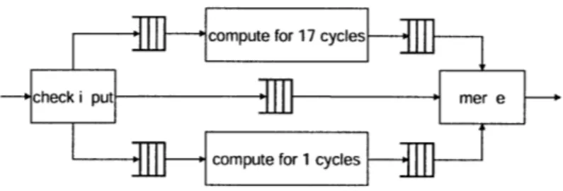
Out-of-order Execution
Figure 4-5 shows a simplified view of the implementation of the Forney's algorithm module. This implementation processes input symbols in the order of their arrivals. Depending on the value of the symbol, the module takes either 17 cycles or one cycle to process it. As it is assured that at most t symbols will need to be processed for 17 cycles in a data block of size k, our non-pipelined design can handle a data block every 17t + (k - t) = k + 16t cycles in the worst case scenario. For example, if t = 16 and k = 223, the design can only accept a new block every 479 cycles.
Data flow analysis shows that there is no data dependency between the computa-tions of the input elements. The only restriction is that results must be forwarded to the next module in the input order. Our original architecture does not take advan-tage of this characteristic because the reference C code implies in-order executions. To increase the throughput, we modified the architecture of our design to support out-of-order executions. We split the module into four sub-modules connected by
if (check error)
ecompute for 17 cycles else
compute for 1 cycle
Figure 4-5: The original structure of the Forney's Algorithm Implementation
FIFOs as shown in Figure 4-6. In the new design, every input is first passed to a sub-module called check input. This sub-module then issues the element to its corresponding processing unit according to its value, and provides merge with the correct order for retrieving data from these processing units. The new design is able to handle a data block every max(17t, k - t) cycles, this translates to a throughput of one block per
272 cycles for this module.
M compute for 17 cycles
--- check i put T m e r e
Scompute for 1 cycles
Figure 4-6: The modified structure of the Forney's Algorithm Implementation
4.2.3
Pipelining
As described earlier, the decoder was set up as a pipeline with streaming data blocks for achieving a high throughput. For hardware efficiency, consecutive modules should be able to share partially computed data to have overlapping execution on a data block. For example, once the Chien search module determines a particular error loca-tion, that location can be forwarded immediately to the Forney's algorithm module for computation of the error magnitude, without waiting for the rest of error loca-tions to be determined. This is algorithmically possible, since there is no dependency
between error locations at this stage. Another requirement for high performance is to have the pipeline stages balanced, with each module processing its input in the same number of cycles.
Both these requirements could be satisfied in Bluespec by the use of explicitly sized FIFO buffers. In the above error location example, having a location vector FIFO between the modules, allowed for significant overlapping execution between the modules. Presence of such buffers between the modules greatly aided in achieving a high throughput.
4.2.4
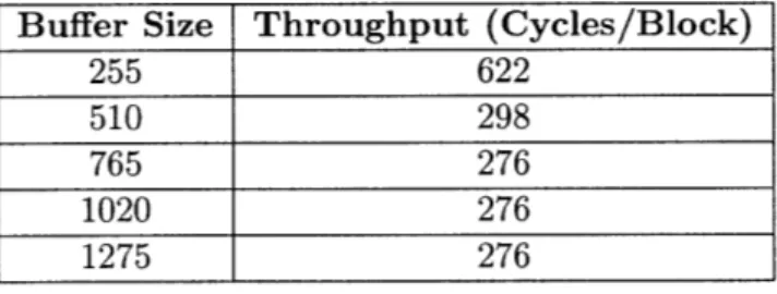
Buffer Sizing
The sizes of the FIFO buffers in the system have a large impact on the system throughput. In a complex system consisting of modules with varying data rates, it is difficult to calculate the optimal size of each buffer. A common method to compute buffer sizes is through design exploration with cycle accurate simulations. It is trivial to adjust the sizes of the FIFOs with the Bluespec library. Table 4.1 shows the performance impact of the sizing of the largest FIFO, which connects the input data port with the Error Correction module. This buffer stores the received data blocks, to be used to compute the decoded result once the errors are computed. We can see from the result that the design achieves maximum throughput when the buffer is large enough to store at least three 255 byte input data blocks.
Buffer Size Throughput (Cycles/Block)
255 622
510 298
765 276
1020 276
1275 276
Table 4.1: Performance impact of Buffer size
Synthesis of this design with a buffer size of 765 bytes showed that this throughput of 276 cycles per input block was sufficient for our requirement, as seen in Chapter 5. The hardware generated was also used significantly less resources than the other designs. This represented the last step of our design process.
Chapter 5
Results and Performance Analysis
At the end of the design process, the final outputs from both design methodologies were used to obtain performance and hardware synthesis metrics for comparison.
5.1
Source code size
The total number of source code lines of the final Bluespec design add up to 1759 lines. On the other hand, source code of the Catapult-C version of the design takes 956 lines and the associated constraints file with the user-specified directives has 90 lines. The increased size of Bluespec code is primarily due to the explicit module interfaces and the associated methods in Bluespec. For comparison, an open source reference RTL implementation [22] has non-parameterized Verilog source code with
3055 lines for n = 255 and t = 16.
5.2
Hardware synthesis results
The designs were configured for design parameters set as n = 255, t = 16, and compiled to RTL. The Bluespec design was generated by Bluespec Compiler ver-sion 2007.08.B. The Catapult-C design was generated using Catapult verver-sion 2006a. Both the RTL designs were then synthesized for Xilinx Virtex-II Pro FPGA using Xilinx ISE version 8.2.03i. The Xilinx IP core for Reed Solomon decoder, version 5.1
Design Bluespec Catapult-C Xilinx
LUTs 5863 29549 2067
FFs 3162 8324 1386
Block RAMs 3 5 4
Equivalent Gate Count 267, 741 596, 730 297,409
Frequency (MHz) 108.5 91.2 145.3
Table 5.1: FPGA synthesis summary
[23], was used as the baseline reference for comparison. Table synthesis summary of the final designs.
5.1 shows the FPGA
5.3
Performance analysis
The designs were then simulated using an extensive testbench to obtain performance metrics. The primary metric in the simulations was determining the number of clock cycles used to process a data block under steady state conditions. Using the maximum operable frequency of the synthesized hardware obtained in Section 5.2, the peak data rates were obtained. These results are shown in Table 5.2.
Design Bluespec Catapult-C Xilinx
Frequency (MHz) 108.5 91.2 145.3
Throughput (Cycles/Block) 276 2073 660
Data rate (Mbps) 701.3 89.7 392.8
Table 5.2: Performance metrics
We can see that the Bluespec design achieves 178% of the Xilinx IP's data rate with 90% of the equivalent gate count. On the other hand, the Catapult-C design, achieves only 23% of the IP's data rate with 200% of the equivalent gate count.
Chapter 6
Conclusion
Through this study we show that even for highly algorithmic code with relatively simple modular structure, architectural issues dominate in determining the quality of hardware generated. If the primary goal of the design is to speedily generate hardware for prototyping or FPGA based simulations without an emphasis on the amount of resources and fine tuned performance, then C-based design offers a shorter design time, provided the generated design fits in the FPGA. On the other hand, high-level HDL languages offer better tools for designing hardware under performance and resource constraints while keeping the benefits of high level abstraction. Insight about hardware architecture like resource constraints, modular dataflow, streaming nature and structured memory accesses can greatly improve the synthesized design. Algorithm designers need intuitive constructs to exert control over these issues. This is difficult to express in languages like C/C++, while hardware-oriented languages like Bluespec offer well defined semantics for such design.
Bibliography
[1] Celoxica, "Handel-C," http://www.celoxica.com.
[2] Mentor Graphics, "Catapult-C," http://www.mentor.com/products/esl/high_ level-synthesis/catapult _synthesis/index.cfm.
[3] Synplicity, "Synplify DSP," http://www.synplicity.com/products/synplifydsp. [4] Synfora, "PICO Platform," http://www.synfora.com/products/products.html. [5] Open SystemC Initiative, "SystemC language," http://www.systemc.org.
[6] G. Stitt, F. Vahid, and W. Najjar, "A code refinement methodology for performance-improved synthesis from C," in
Pro-ceedings of ICCAD'06, San Jose, CA, November 2006. [Online].
Avail-able: http://www.cs.ucr.edu/~vahid/pubs/iccad06_guidelines.pdfhttp://www. cs.ucr.edu/~vahid/pubs/iccad06_guidelines.ppt
[7] Y. Guo, D. McCain, J. R. Cavallaro, and A. Takach, "Rapid Prototyping and SoC Design of 3G/4G Wireless Systems Using an HLS Methodology," EURASIP
Journal on Embedded Systems, vol. 2006, no. 1, pp. 18-18, 2006.
[8] Y. Guo and D. McCain, "Rapid Prototyping and VLSI Exploration for 3G/4G MIMO Wireless Systems Using Integrated Catapult-C Methodology," in
Proceed-ings of Wireless Communications and Networking Conference (WCNC), 2006,
pp. 958-963.
[10] K. M. Chandy and J. Misra, Parallel Program Design: A Foundation. Reading, Massachusetts: Addison-Wesley, 1988.
[11] J. C. Hoe and Arvind, "Synthesis of Operation-Centric Hardware Descriptions," in Proceedings of ICCAD'O0, San Jose, CA, 2000, pp. 511-518.
[12] N. Dave, M. Pellauer, S. Gerding, and Arvind, "802.11a Transmitter: A Case Study in Microarchitectural Exploration," in Proceedings of MEMOCODE'06, Napa, CA, 2006.
[13] M. C. Ng, M. Vijayaraghavan, G. Raghavan, N. Dave, J. Hicks, and Arvind, "From WiFI to WiMAX: Techniques for IP Reuse Across Different OFDM Pro-tocols," in Proceedings of MEMOCODE'07, Nice, France, 2007.
[14] K. Fleming, C.-C. Lin, N. Dave, J. Hicks, G. Raghavan, and Arvind, "H.264 De-coding: A Case Study in Late Design-Cycle Changes," in Proceedings of
MEM-OCODE'08, Anaheim, CA, 2008.
[15] N. Dave, "Designing a Reorder Buffer in Bluespec," in Proceedings of
MEM-OCODE'04, San Diego, CA, 2004.
[16] N. Dave, M. C. Ng, and Arvind, "Automatic synthesis of cache-coherence proto-col processors using Bluespec," in Proceedings of MEMOCODE'05, Verona, Italy, 2005.
[17] IEEE standard 802.16. Air Interface for Fixed Broadband Wireless Access
Sys-tems, IEEE, 2004.
[18] S. B. Wicker and V. Bhargava, Reed-Solomon Codes and Their Applications. New York: IEEE Press, 1994.
[19] T. K. Moon, Error Correction Coding-mathematical methods and Algorithms. New York: Wiley-Interscience, 2005.
[21] S. A. Edwards, "The Challenges of Synthesizing Hardware from C-Like Lan-guages," IEEE Design and Test of Computers, vol. 23, no. 5, pp. 375-386, May 2006.
[22] Ming-Han Lei, "Reference Verilog Implementation," http://www.humanistic. org/~hendrik/reed-solomon/index.html.
[23] Xilinx, "CORE Reed Solomon Decoder IP v5.1," http://www.xilinx.com/ ipcenter/coregen/coregeniplist_71i_ip2.htm.


![Table 5.1: FPGA synthesis summary [23], was used as the baseline reference for comparison](https://thumb-eu.123doks.com/thumbv2/123doknet/14409674.511475/35.918.230.697.101.238/table-fpga-synthesis-summary-used-baseline-reference-comparison.webp)
