design | make
the translation of design intention to fabrication
byJames R McLain, Jr
Bachelor of Architecture The University of Arizona, 2004
Submitted to the Department of Architecture
In Partial Fulfi llment of the Requirements for the Degree of Master of Science
at the
Massachusetts Institute of Technology
September 2007
© 2007 James R McLain, Jr. All rights reserved.
The author hereby grants to MIT permission to reproduce and to distribute publicly paper and electronic copies of this thesis document in whole or in part in any medium now known or hereafter created.
Signature of Author Certifi ed by Accepted by
...
Department of Architecture 10 August 2007...
Lawrence Sass Assistant Professor of Architecture Thesis Supervisor...
Julian Beinart Professor of Architecture Chairman of the Department Committee on Graduate Students
Committee
[thesis advisor]
Lawrence Sass, Assistant Professor Department of Architecture, MIT
[thesis reader]
Terry Knight, Professor Department of Architecture, MIT
Abstract
[abstract]
The process of making innovative buildings is stifl ed by our current methodology of communicating design information. Advances in new techniques, technologies, methods, materials and knowledge for both designers and constructors have failed to successfully be implemented into the building industry because of our reliance on traditional methods of transmission and exchange.
The purpose of this thesis is to survey our current methods and propose an alternative process of communicating complex design information through a hypothetical design problem and subsequent physical fabrication. The objective of the research is to develop a process for designing, communicating and making of innovative parts / assemblies that will allow designers and fabricators to effi ciently increase the quality of the products they produce.
design | make the translation of design intention to fabrication by
James R McLain, Jr
Submitted to the Department of Architecture on August 10, 2007 in partial fulfi llment of the requirements for the Degree of Master of Science in the Department of Architecture.
Thesis Supervisor: Lawrence Sass
Acknowledgements
Like any ambitious effort, this work would not be possible without a great deal of assistance. Special thanks to…My Parents
for instilling work ethic and the value of education
My Sister
for blazing a trail and setting the bar high
Larry Sass
for his limitless enthusiasm and persuasion to push me further then I thought I could go
Terry Knight
for her guidance, support, and introduction to new explorations
Simon Kim & Tom Plewe
for their friendship, support, and Wednesday night BBB’s
Chris Trumble, John Folan & Alvaro Malo
for mentoring and encouraging me to pursue this endeavor
Page Repp & Stacy Burnett
for their ideology and beliefs that laid the foundation for this investigation
Luis Ibarra & Teresa Rosano
for their passion and rigor that is an inspiration
Michael, Denyse, Colleen, Julianne & Danielle Turpin
for making me feel at home and keeping me grounded
and above all Brandy
my wife, for her endless support, love, encouragement, patients, friendship, and advice who without her, none of this would have been possible.
Title page Committee Abstract Acknowledgements Contents 1.0 Introduction 1.1 Motivation
1.2 Research Objective + Outline 1.3 Importance of Research 1.4 Uniqueness of Study 1.5 Past Research 2.0 Background & Purpose
2.1 Process: History of the Designer and Constructor Relationship
2.2 Making: Idea to Physical Output 3.0 Architectural Design Problem
3.1 Purpose
3.2 Architectural Program 3.3 Construction Program 3.4 Proposed Solution
3.5 Design Information Translation Comparison 4.0 Hypothesis
4.1 Broad Research Question 4.2 Secondary Research Question 4.3 Expected Results
4.4 Contribution to Research 5.0 Methodology
5.1 Process of Investigation
5.2 Designing the Fabrication Process 6.0 Experimentation 6.1 Introduction 6.2 Process
Contents
07 10 20 30 33 426.0 Experimentation (continued) 6.3 Formwork 1 6.4 Formwork 2 6.5 Formwork 3 6.6 Formwork 4 6.7 Formwork 5 6.8 Formwork 6 6.9 Formwork 7 6.10 Formwork 8 6.11 Formwork 9 6.12 Formwork 10 6.13 Formwork 11
6.14 Transferring Design Information 7.0 Conclusion
7.1 Summary of Formwork Experiments
7.2 Design & Fabrication Process Methodology + Knowledge 7.3 Making 7.4 Implementation 8.0 Figures 9.0 Bibliography 79 94 98
1.0 Introduction
1.1 MotivationThe success of making a building can be directly related to the management of information. Concepts are derived from a client’s needs and desires, site characteristics, and building codes. These concepts are then developed and refi ned into an agreed upon solution that satisfi es the owner, architect, engineer and municipality. This solution is then translated and packaged into graphical drawings and specifi cations on paper and delivered to the constructor. The constructor then translates the graphical drawings and specifi cations into the physical artifact.
This relatively simplifi ed sequence (Fig. 1.1.A) illustrates many of the inherent diffi culties within the building industry today.
As illustrated from the above diagram, the potential for information breakdown becomes clearly visible. Architects work with owners to design buildings three dimensionally. They utilize computer and physical modeling to convey ideas and exchange information at scales from the largest urban context to the smallest fastener. This three-dimensional information is then translated by the architect into plans, sections, elevations, and text that are graphically accepted methods of communication. Constructors then must work to re-translate the information conveyed in the plans, sections, elevations and text into a physical three-dimensional object by developing the means and methods used to create the desired outcome. When mistakes occur during the construction process they can almost always be rooted
to either information that failed to be conveyed in the drawings, misunderstood by an entity within the constructor team, or executed by means and methods not considered during the design.
1.2 Reach Objective & Outline
The objective of this research is to develop a new method in which complex design information can be better communicated to the fabricators making the building. This thesis will also look at the processes and techniques that are currently used and the ones that are poised to transform the industry.
This investigation begins with a survey describing the development of the relationship between the designer and fabricator to understand how the industry has arrived at its current mindset. From there a hypothetical architectural design problem of desert relief shelters (Fig. 1.2.B.1), propagated throughout southern Arizona, is laid out and subsequently utilized to illustrate a newly proposed design translation methodology (Fig. 1.2.B.2).
From the methodology, the fabrication process for a component is designed and a method of creating rapidly generated mass customized concrete formwork through negative layer fabrication (Fig. 1.2.B.3) was conceived. After rigorous experimentation, the process was refi ned and the methodology tested. Finally, extracted conclusions from the work are summarized.
1.3 Importance of Research
The importance of this research can be described by three presumptions. First, our capacity to create better and more innovative buildings is increasing but is being stifl ed by our inability to change our design to construction methodology to embrace these new advances. Second, the separation between the designer and the
fabricator is distant and growing; however, the advantages of a fl uid relationship are mutually benefi cial. Lastly, making buildings requires more graphical and textual information than ever before, causing the need for appropriately and effi ciently managed information critical to the success of a project.
1.4 Uniqueness of Study
The investigation of this study is unique in several ways. It focuses on fabrication issues within small scale projects with modest budgets in contrast of unlimitedly funded projects where the only constraint is the designer’s imagination. By limiting the cost as a dependent variable, it forces realistic decision making that can be more easily implemented into the mass market. Also, the aim of this thesis is to propose a new methodology and reveal technical information through physical application.
1.5 Past Research
Previous research resides in two primary streams, the theory of making and the development of new technologies and materials. Professional practitioners such as Gehry Partners, Kieran & Timberlake, William Massie and Tri Pyramid have all examined the process of building and contribute to the evolution of fabrication and the role of making in architecture. They also propose directions for improvements and distain for fl awed process. Technical information for emerging tools and materials is widely available. Research has been executed both in pragmatic and academic settings. The aim of this research is to propose new theory and defend it through technical means and methods.
2.0 Background & Purpose
2.1 Process: History of the Designer and Constructor Relationship [master builder]In 1418, Filippo Brunelleschi entered a competition to “make any model or design for the vaulting of the main dome” (King 200) of the Santa Maria del Fiore Cathedral (Fig. 2.1.A) under construction in Florence, Italy. Original building had been started on the Cathedral in 1296 but the design called for an enormous dome (143 feet in diameter) to be constructed hundreds of feet in the air with no fl ying buttresses that typically supported the lateral loads of Cathedrals all over Europe. Brunelleschi engineered the dome by designing the angled placement of all brick in combination with the ribbed arch supports. The material composition of the brick and mortar was developed to achieve the desired fi nal loading and support during construction. He created the dome as an architectural keystone, perfect in proportion, scale, and space. Not only did he supervise the building process but he also developed the tools required for construction such as the helical screw jack (Fig. 2.1.B). Finally, he managed the scheduling and juggled the politics.
Brunelleschi was a master builder. By combining the roles of engineer, material scientist, architect, builder, and manager he was able to maintain a clear singular vision and account for all processes in order to achieve what was thought to be an impossible endeavor.
More then 200 years later, during the Japanese Edo Period (1603– 1868), the ideology of the master builder still existed. At this time it was manifested through the master carpenters responsible for building temples (Fig. 2.1.C), shrines and tea houses. They were referred to as Daiku whose etymology was derived from “chief” and “artisan”. They were held in high social regard and according to Buntrock, “were the only trade that was, as a rule, allowed to sign their work, a privilege otherwise specifi cally extended only to the most talented crafters”. (Buntrock 2002)
[segmentation & specialization]
Sometime between the end of the Japanese Edo Period and now, the profession of making buildings has become divided and segmented.
Figure 2.1.A
Figure 2.1.C Figure 2.1.B
The role of architect, builder, engineer, material scientist, and manager are now fi ve distinct entities. It is obvious that this division occurred when buildings became increasingly more complex with the advancement of new materials and technology. However, negative ramifi cations have rippled throughout the industry in response. Communications between the fi ve entities becomes absolutely critical. Improperly managed information can cause anything from slight mistakes to enormous crippling errors. The constructor has now assumed the role of the means and methods of construction. Innovative techniques for accomplishing novel tasks such as Brunelleschi’s screw jack are now often value engineered from the project and reduced to conventional methods. In this scenario, Brunelleschi’s dome would have been deemed impossible to build and may never have been realized.
The architect is now responsible for orchestrating a multitude of entities with often differing self interests. A singular vision is blurred, confl ict begins to occur, ineffi ciencies start to arise, and litigation becomes common practice. Overall innovation begins to slow; better ideas are sacrifi ced for conservative solutions, and the entire building industry progression is stifl ed.
[downfall of our current methods]
The problems in current professional practice are not solely from the segmentation of separate entities but from a variety of ineffi cient methods ingrained into conventional process.
We utilize two dimensional paper drawings (Fig. 2.1.D) as our current method of translating design information because it was the best technology available at the time it was developed. Hence, designs for buildings were also conceived and worked through with clients on these two dimensional paper drawings which made for an effi cient translation to constructors. Currently, designers utilize paper drawings, digital computer models, renderings, physical models, and mockups to exchange design intention with their clients. It is overly optimistic to assume that constructors can extract all the information of these newer techniques when the rich design information is translated back into archaic two dimensional paper drawings. When creating complex buildings, two solutions exist to owners and architects. Either hire only exceptionally skilled contractors able to decipher and execute mass amounts of design information or change our current methodology of translating design intention.
H.H. Richardson was able to construct Sever Hall at Harvard University (Fig. 2.1.E) with 6 sheets of drawings in 1880. (Jennings 2007) A current building of comparable size and scope is likely to be more then a hundred pages of drawings accompanied by several hundred pages of specifi cations. The amount of information transferred between hundreds and sometimes thousands of people is at an all time high. Communication can become time consuming and painstaking. The ability to embed a greater amount of information in less volume will lower mistakes yielding higher quality buildings at less expensive prices.
As illustrated by the building industry value chain below (Fig.2.1.F), our current methodology reiterates the fact that increasing the separation between the designer (who conceptualizes the part) and the fabricator (who makes the part) increases the cost and decreases
the clarity of intention.
The law of economy and value states that Quality x Scope = Cost x Time. This is the current paradigm in which the production of buildings exists today. The desirable aspects of anything we make are quality and scope. We like things that are made well; they have craft and an increased longevity. This country is also a consumption based market, if we like something we want more of if and we increase its scope. In contrast, we tend to dislike cost and time. Cost and time are the limiting factors that determine the quality and scope of something we want.
Automotive industries have been working to change the law of economy to meet new client mandates, the revised equation now reads, Quality x Scope > Cost x Time. The price of automobiles rise slightly ever year but the amount of features increases much faster. In other words, consumers are demanding more for less. According to Kieran, “These lessons are not about outward form, style, or
Figure 2.1.F Figure 2.1.E
appearance. They are about processes and materials developed over the past decade that have overturned the ancient equilibrium between expenditure or resources and acquisition of benefi ts.” “Anybody can give you more for more; it takes a real genius to give you more for less.” (Kieran 2004)
[practice]
Until recently, three major contract types for delivering a project from design to construction existed. Traditional delivery, also know as design – bid – build was the predominant mode of delivery in the U.S. for many years (Gould 2000). In this method, owners would hire an architect to prepare a design and subsequently construction documents. The owner would then either enter into a competitive bid for the lowest construction price or work with a contractor for a negotiated fee. The advantage of design – bid – build is its familiarity within the industry making it easily accessible for a large population. Another popular delivery method is referred to as design / build. Design / build project delivery can either exist as a single entity that provides both in house design and construction services or may be two separate fi rms that create a joint venture for a specifi c project. The advantages of design / build are that an owner has one point of contact throughout the entire project and the team approach between the designer and contractor makes for much better communication. Also, both the design and construction teams share a common goal and liability making for a less adversarial relationship when compared to traditional delivery. Although there are many advantages to design / build there are equally as many disadvantages. First, it is diffi cult for an owner to obtain a GMP (guaranteed maximum price) early in the project because with a shared interest the design fi rm could potentially tailor the design of the project to meet healthy profi ts for the construction. Instead, owners must provide a general idea of project cost and solidify pricing near construction document completion. Second, there exist few checks and balances within design / build. In traditional delivery, the architects become consultants to the owner during construction to verify the quality of work being performed. This is more diffi cult to achieve in design / build unless a third party fi rm is brought in to oversee performance.
The last common delivery method is Construction Manager usually executed as Construction Manager at Risk (CM at Risk). In this method, an owner hires an architect and construction manager early in the project. Both the architect and construction manager report
to the owner but communication is improved because of the dual entitles working together. As the design progresses the construction manager is able to provide cost and schedule information to the owner to assist in decision making. At the end of construction documents the construction manager provides the owner with a guaranteed maximum price and construction commences. The advantages of this method are the good communication between the architect and contractor combined with the separation of power which is usually more appealing to the owner. The disadvantage to construction manager delivery is the potential for team members to become infl exible or unavailable. Also, while the owner may enjoy not having to worry about potential cost overruns the contractor has most certainly accounted for this by increasing the contract price. If the market is stable, the contractor stands to make a large sum of money. Conversely, if the market turns down (prices increase) the contractor may take a large loss.
[emerging practice]
The above three project delivery methods are commonly used to handle the majority of typical construction within the U.S. However, many architects and contractors involved in producing innovative projects have found it diffi cult to produce their work within the established methods. In response, several new methods of project delivery have emerged to improve the relationship between designing and making.
[integrated practice]
“The ineffi ciencies inherent in the process of design and construction are necessitating a shift to greater multidisciplinary collaboration and information sharing among project team members”, according to Pressman. (Pressman 2007) The idea behind Integrated Practice is similar to design / build but involves a larger scope of people involved within the project. Architects, owners, and constructors work with design consultants, sub contractors, and suppliers to meet project goals together. They typically employ new technology to exchange vast amounts of information and decision making is more collective. The concept of designer ownership is replaced with team authorship.
[fabricators as consultants]
Gehry Partners changed the model of standard architectural practice when they found the current process non conducive to implementing their building typology. Because of the inventiveness of their designs,
it would have been impossible to deliver their projects via one of the 3 traditional project delivery methods. There was a high risk of developing a project that was non constructible. In order to accommodate their production, Gehry Partners brought in fabricators early into the design process. By doing this, they guaranteed that their design solutions could be executed to an expected level of quality at a proposed price and timeline. (Fig. 2.1.G)
[manufactures as designers]
Recognizing the disconnect between high design and manufacturing, Tim Eliasen founded Tri Pyramid Structures (Fig. 2.1.H) to be a full production manufacturing facility with a design studio in the next room. In this model, designers work side by side with the machinist fabricating the parts. Feedback loops are instantaneous and communication between the two entities is seamless.
2.2 Making: Idea to Physical Output
[evolution}
Assemblies are generated in 3 ways, a singular craft, an assembly line, and modularized and component construction. Many industries in the business of making have evolved through these methods. For example, early automobiles predating the 1913 Ford ‘Model T’ were constructed individually by expert mechanics that knew the workings of every part. The assembly line (Fig. 2.2.A), which followed singular craft, increased production and improved performance of the product. Currently, automobiles are constructed by modularized components (fi g. 2.2.B). The instrument panel, drive train and cockpit are all separate objects fully constructed in ideal conditions and brought together for fi nal assembly.
[parts, connections & assemblies]
The connotation of the word connection often infers the joining of two objects together. Assembly means the joining of many things together. The making of buildings often focuses on its parts as isolated pieces. We tend to think of components as separate objects, a window, a light fi xture, a door handle, and a tile. Looking deeper, a duct, a vent pipe, a circuit breaker, and a vapor barrier. Why has this occurred? Building components are produced by individual companies with separate interests, such as performance, aesthetic or cost. Another industry
Figure 2.1.H Figure 2.1.G
Figure 2.2.A
exists solely to serve the joining of isolated objects. Screws, bolts, nails, glue, and tape are a critical part of building but over reliance on their use is diminishing quality when compared to a well thought out assembly. Caulk, foam, spackle and trim exist almost entirely to cover up mistakes and differences when joining objects together.
The ability of architects to design the connection of materials in such a way to minimize assembly error and increase craft through material imposed constraints is no longer held to a visual standard only. Is it possible to design the assembly of objects in such away that it only ‘fi ts’ correctly?
[craft]
Craft is a diminishing characteristic. Pride in one’s work is quickly being replaced by sentiments of faster and cheaper. With the loss of craft, construction becomes sloppy and wasteful. When exterior materials do not align air infi ltrates the layer. HVAC systems work harder to adjust climatic conditions, energy is wasted, bills increase and more greenhouse gases are emitted. Exterior materials break down at a rapidly increased rate when not installed accurately or to a specifi ed level of fi nish. A poor weather proofi ng installation will diminish the useable life of the building, costing the owner more money, wasting materials, and causing higher litigation fees for the building industry. Craft is not tied solely to a buildings visible appearance but instead its overall performance, longevity, usefulness, and cost.
[handcraft vs machine craft]
Not long ago, handcraft was the only method of producing. Tremendous amounts of human effort (Fig. 2.2.C) and time were expended to make. Handcraft was not a luxury, the economies of the situation still needed to prevail. Machine craft was a dream that would allow for less human effort and time to produce greater quality at a better cost. As previously mentioned, many industries such as the automobile, aerospace, electronics and product making industry have all embraced machine craft. Time has refi ned their processes and has allowed designers and fabricators to work with their tools in an integrated fashion. The building industry has failed to fully realize the potential of a better methodology. The outcries shaming the loss of human craft were soon drowned out by inexpensive production building that exploited “human craft” to its lowest possible price without regard for quality (Fig. 2.2.D). The economies of the situation prevailed. Actual human craft is a luxury afforded to large budget
Figure 2.2.C
projects, machine craft integrated with designers and fabricators is a method of providing quality at a better price.
[mass production vs. mass customization]
Mass production was the ideal method of making for the 20th century.
Standardized processes allowed for one object to be repeated in enormous quantities. By doing so, quality remained consistent and costs remained low. Mass customization is the new method of making for the 21st century. Process models are designed with a degree of
fl exibility to allow products to be tuned to the needs of the consumer. Dell Computers pioneered early work in mass customization by allowing customers to select their specifi c confi guration to meet their needs. Internally, Dell organized production by accommodating variation to a limit, which allowed for the product to still be produced in high volume and at a controlled cost without becoming a one-off supplier.
[emerging design methods]
Tools that designers work with to conceive, develop and produce design information are also evolving. For more then 200 years, architects have used paper drawings to communicate design intention. (Woods 1999) However, as buildings become increasingly complex with systems and detailed components the limitations in conveying information strictly through two dimensional drawings is evident. In response, designers are switching to improved methods of working with design information. Solid modeling (Fig. 2.2.E) is object based design software that simulates real life conditions within a digital environment. Typical problems of tolerance, part confl ict, connection fi tting and space for construction work are overcome with every part worked out three dimensionally and considered dependent of its assembly.
Parametric modeling (Fig. 2.2.F) combines solid modeling with the ability to create hierarchical and bi directional dependencies within the model. Therefore, if the size of one component, such as a piece of steel, is changed all elements that have a direct relationship with that element can automatically adjust and accommodate the modifi cation. This technology drastically reduces revision time and human oversight. However, it is important to point out that parametrics are most useful when applied to conditions where the possibility of change is foreseen and minimum and maximum limits are defi ned. Because
Figure 2.2.E
of the hierarchical nature of the structure, it is impossible to link every element together without creating self-referential geometry. Thus, certain elements must drive and other elements must be driven within the model.
Building information modeling (Fig. 2.2.G), or BIM, is the fastest growing new tool with the largest user base only second to traditional representation. BIM allows users to embed data directly into digital models that provide teams with quickly extractable information such as components size, manufacture, fi nish, cost and schedule. “More than a new way of drafting, BIM is really a paradigm shift for design and construction. Its adoption forces examination of a host of practice and business issues, from the defi nition of professional roles to liability to project delivery methods”. (Gonchar 2007)
[emerging fabricating methods]
Advancements in fabrication have improved the process of making at both the model scale and full size production levels. These new technologies can be divided into 2 major categories, additive process machines and subtractive process machines. (Seely 2004)
Additive process machines make by physically adding material in a layered fashion to create a desired shape. Fused Deposition Modeling and ZCorp (Fig. 2.2.H) printing are two examples of such machines. Both operate in a similar fashion to an ink jet printer in that a head moves back and forth on a gantry applying material. Additive process machines are good extensions of three dimensional digital computer modeling. With relatively little translation, these digital models can be sent directly to the machine and a physical model is ready in a matter of hours. These machines are mostly used for rapid prototyping, quickly modeling something before it is sent to production. Rarely do these machines provide actual products; they are utilized more as representational tools for real life simulation.
Subtractive process machines include laser cutters (Fig. 2.2.I), water jet cutters and numerically controlled routers often referred to as CNC machines (Fig. 2.2.J). In subtractive process machines, sheet material is inserted into the device and is cut, routed or milled (subtracted) to reach the desired outcome. Small size laser cutters are generally used for modeling purposes and can be easily scaled up to production with a CNC router. In contrast to an additive process machine which can easily accept any three-dimensional shape sometimes users have to translate their designs to accommodate
Figure 2.2.H
Figure 2.2.I Figure 2.2.G
subtractive process machines. CNC routers can do a certain amount of milling (three dimensional surfacing) but usually up to 4” on a 48” x 96’ table. In most cases, two-dimensional shapes are cut from sheets and assembled to create three-dimensional forms. Hence, models that are derived three dimensionally are then user translated to two-dimensional cut sheets. Translation error, connections and tolerance all become factors that need to be considered in the design to facilitate its making.
3.0 Architectural Design Problem
3.1 Purpose
In order to test the effectiveness of a new methodology that deals with the translation of design intention into fabrication, a hypothetical design problem was set up and tested. The conditions of the design problem were to be as follows. First, the project had to contain some portion in which a custom component could be identifi ed and the means and methods for fabricating it could be explored at great length to unveil undiscovered knowledge. Second, the project had to be small in budget and subsequently most likely small in scale. The reason for a small budget is that anything can be fabricated with enough money, to really advance the methodology an economic constraint forces realistic conditions and practical solutions.
3.2 Architectural Program
For the design problem, a multipurpose remotely located desert relief shelter was selected. The following architectural program was initialized.
Use Refuge from the sun and harsh desert
environment; collection of rain water, passive solar energy, wind.
Typical occupants Shelter for campers, hikers, hunters, nature researchers, off road enthusiasts, migrant border crosses, border patrol agents.
Size Approximately 200 to 400 square feet.
Location Various spots located remotely (greater then 25 miles from any fairly populated communities within the southwestern US).
Materials To be determined during the design process.
Structure To be determined during the design process.
Systems No active electrical, mechanical or plumbing systems – subsistent systems only.
3.3 Construction Program
Because it was determined early on that the purpose of this project was to investigate a potentially new methodology for making buildings the construction program became as equally important as the architectural program in terms of defi ning constraints that would add to the depth of the research and make it a more realistic project.
Transportation The building components must be delivered to a variety of remote sites by truck and trailer (non semi) in an economical manner
Utilities No onsite water, gas, or electricity will be assumed to be provided. Any utilities required for fi eld construction will need to be transported and considered part of the design solution.
Field Assembly Field construction must take place by hand – it is assumed that no cranes of heavy lifting equipment will be available. 3.4 Proposed Solution
[site]
The proposed project sites are located within the rural areas of the southern region of the state of Arizona (Fig.3.4.B). These areas are shared by a variety of people including campers, hikers, hunters, nature researchers, off road enthusiast, migrant border crossers, and border patrol agents.
The shaded area of the map shows the approximate amount of land located more then 25 miles from a fairly populated area (Fig.3.4.C). Twenty one different sites for desert shelters have been identifi ed. The site located between Tucson and Sells, Arizona and will serve as the typical site for this investigation. It is located on a slight east slope against the base of several large hills directly to the south.
The proposed design of the shelter will allow for the same design to be constructed at each of the outlined locations. However, the foundation and fl oor plates will be customizable to accommodate the terrain discrepancies between each location.
The site is predominately rocky with hard soil and mixed desert vegetation (Fig.3.4.D). The prevailing breeze comes from the northwest but it is likely to get winds from any direction. Tucson is
Figure 3.4.B
approximately 35 miles to the northeast and Sells is approximately 35 miles to the southwest. Interstate-10 is approximately 27 miles due east. There are no man made features near the site. The minimum soil bearing pressure for Pima County is 1500 PSF. The annual rainfall in this area is 12.26”.
[conceptual drawings] Section
This building serves as a vessel for collection and release (Fig.3.4.F). Varieties of temporary inhabitants briefl y use the shelter as relief from the harsh desert environment before going on their way again. Water is collected during desert rains and stored in the cavity of the bearing walls to be later used by people.
The fl oor panels are mass customized to accommodate terrain variations between different sites (Fig.3.4.G).
Plan
The plan of the structure serves to block the hot west sun with the west walls (Fig.3.4.H). The south sun, which is controlled by the specifi ed roof overhang, being blocked during the summer and let in for warmth during the winter (Fig.3.4.I).
Figure 3.4.D
Figure 3.4.F
Figure 3.4.H Figure 3.4.G Figure 3.4.G
[structure & material concepts]
The structure of the shelter is comprised of four primary parts (Fig.3.4.J). The roof sheeting, roof trusses, mass customized concrete wall units and mass customized fl oor panels.
Figure 3.4.I
The concrete wall units are mass customized into 5 primary shapes that allow the current confi guration (Fig.3.4.K). By alternating the arrangement of the connections any variety of confi gurations is possible.
Figure 3.4.K
Figure 3.4.L Figure 3.4.L
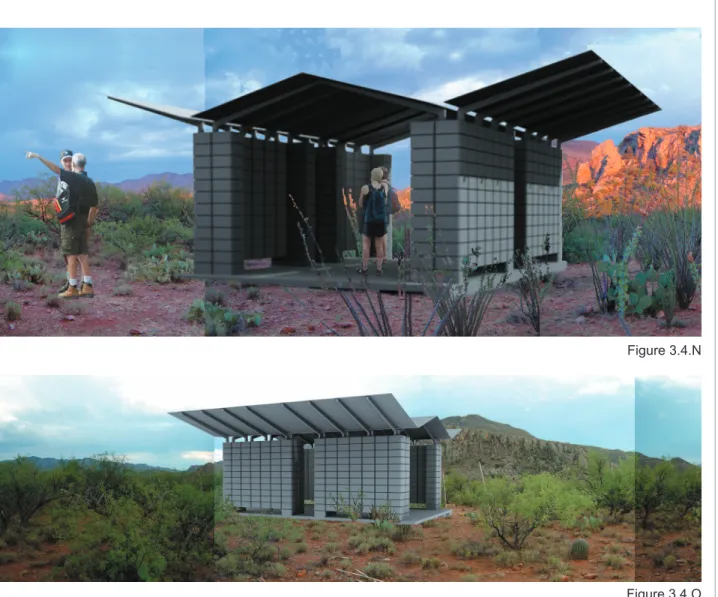
[design solution]
The above renderings shows the fully developed design of the desert relief shelter.
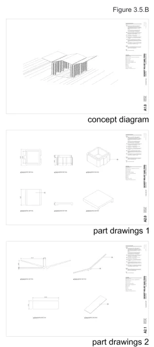
3.5 Design Information Translation Comparison
At this point, in a typical project, the above design would now be translated into two dimensional drawings that communicate the design information. For comparison, drawings of the project have been produced in both the traditional method (Fig. 3.5.A) of commonly accepted graphical drawings and a potentially new method (Fig. 3.5.B) of component based fabrication drawings and assembly instructions.
Figure 3.4.O Figure 3.4.N
Figure 3.5.A Figure 3.5.B
From the comparison of the below two methods it is visible to see that the traditional method of translating design information into construction requires a highly skilled constructor to interpret the intent and implement the means & methods required to execute the design. The proposed method of translating design information provides the constructor much clearer information and should hypothetically make the construction process easier.
4.0 Hypothesis
4.1 Broad Research QuestionAs illustrated by the previous comparison of traditional design translation with a proposed alternative; in addition with all of the inconsistencies that exist in our current building industry mindset combined with our emerging tools and processes, is it possible to create a new methodology of translating design intention into fabrication?
The major advantages of successfully developing such a system would be the ability for designers to offer their clients higher quality products at a lower cost and reduced amount of time. This would be achieved by the designer again taking an active role in the means and methods of production and repackaging that information to communicate the necessary intention in the least amount of output. This type of methodology is geared towards tectonic based architecture with a kit-of-part assembly.
The potential disadvantages of the new methodology could be the imbalance of liability and risk when inserted into the current insurance system. These obstacles could be overcome by reorganizing coverage or operating in collective intelligence. Also, this type of methodology may not work well for projects in which little part fabrication is required.
4.2 Secondary Research Question
From the broad hypothesis, the next pertinent questions would ask, what is the method for translating and designing the fabrication process of a part based building? How do you go about designing a process that can be applied to a wide variety of potential design problems? For this a series of steps will need to be developed. Careful distinctions will need to be made in order to separate linear and methodical process from free fl owing designing. It is also easy to quickly isolate part design and therefore the design process should include the ability to create the part in consideration of the entire assembly.
4.3 Expected Results
The aim of this thesis will seek to investigate four expected results concerning method, process, communication, and fabrication.
[method]
A new methodology that expands from traditional process and seeks a way of embracing emerging technology, skills and materials under the constraints of the mindset of the current building industry will fl ourish in its ability to create higher quality products for less time and cost.
[process]
The ability to design the means and methods in which complex components will be fabricated ensures fewer errors in the product providing better quality. It is expected to show that when a designer only produces graphical information depicting the fi nal iteration of a part there is a lack of embedded information that the designer is not able to communicate through traditional channels. By designing the process in which the part will be made, the designer embeds another level of design information such as but not limited to, tolerance, part relationship to the whole, and assembly information.
[communication]
By considering the ways in which things will be made, designers have the ability to embed intelligent information concerning its fabrication directly into the part. For instance by designing a joint that can only be installed only one way, less graphical and textual information needs to be provided in the drawing set depicting the proper orientation of the said part. When this principal is arrayed throughout the entire process, the amount of information that a constructor must manage is greatly reduced and allows him or her to perform better in less time.
[fabrication]
Just as machine craft and mass production were the idealized manufacturing methods at the turn of the last century; mass customization, automation and rapid generation are the emerging tools for this century. Mass customization will allow designers to produce unique and specifi c parts more effi ciently through the reduction of waste. Rapid generation and automation will assist this production with the ability to create continuous diverse parts at mass produced
speeds. This new system of making will also provide consistent high quality without the dependency on high cost skilled labor.
In summary, the expect results of this investigation will show that designers, consultants, constructors, fabricators and owners will reap the benefi ts of a methodology that allows projects to be designed and made better (performatively, functionally, spatially, and aesthetically) for less cost (more effi cient, fewer mistakes, accurate pricing, and less time) and / or higher value (better performance providing increased value to the client).
4.4 Contributions to Research
The intention is to provide both designers and fabricators new knowledge for their fi elds. For designers, this thesis will provide an alternative method in which to communicate their design intentions to the person physically constructing their work. It outlines an example of the design of a fabrication process that can be implemented into an infi nite variety of component design situations. At a minimum, the hope is that a designer reading this will at least have a greater appreciation for the person in the shop or in the fi eld that works hard to produce the best quality product but is often stifl ed through poor communication and misunderstanding.
For the fabricators, the goal of this project is to provide both theoretical and technical information regarding the making of non-traditional, complex parts and components. It outlines the development of the relationship between design and making, the existing and proposed methods of producing, and the importance of evolving the existing paradigm. In terms of technical information, the advantages and disadvantages of new tools are demonstrated and a rich amount of amount of data is provided regarding the production of rapidly generated mass customized concrete units through negative layer fabrication. This data discusses tolerance, assembly, formwork design, reusability, releasability, integrated & secondary connections, material considerations, and the relationship between the design to the tool and the tool to the product.
5.0 Methodology
5.1 Process of InvestigationThe underlying basis for this investigation is to create a new methodology for effectively translating design intention into fabrication that can be applied to a wide variety of applications. To facilitate this process the design for the remotely located desert shelters has been utilized to test the proposed theory.
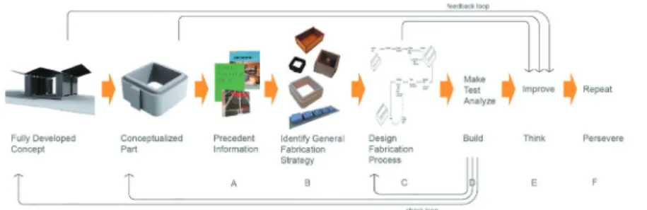
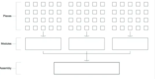
As illustrated in the above diagram (Fig. 5.1.A) there are a proposed four steps when taking the remotely located desert shelters from a fully developed design to its information for construction.
Step 1 – Determine all parts within the building.
The desert shelters contain 4 major parts for its construction. 1. Mass customizable concrete fl oor panels
2. Mass customizable concrete wall units 3. Roof trusses
4. Sheet Roofi ng
Step 2 – Design the fabrication process for each part
These may vary widely depending on the type of part and its material. For example, a metal roof panel would only require the standardized panel itself and a template (or jig depending on complexity) for cutting it to the correct shape and size. In contrast, the design of the concrete wall units would require
an involved process of designing rapidly generated formwork that can produce mass customized concrete wall units.
Step 3 – Packaging the fabrication method for each part
This step requires identifying and producing the information needed for the means and methods of each part. As mentioned above, a metal roof panel would require a drawing of a template used for cutting (or perhaps a physical template itself). The concrete wall units would require an extensive process of designing a fabrication method and then testing and refi ning until it has met performance standards. At that point, packaging the concrete wall units may be the GCode (data required for a CNC machine to cut material), a material list and instructions to facilitate the production of the formwork and casting.
Step 4 – Preparing assembly instructions
Since the means and methods for fabricating each part has now been developed and packaged a set of instructions for carrying out the rest of the assembly needs to be implemented. This set of instructions would merge the material list for each component into a combined bill of materials that could be expanded or reduced depending on the desired design of the desert shelter. Assembly instructions depicting a sequential order of placing and connecting parts would then follow. 5.2 Designing the Fabrication Process
To test whether this methodology could be successful this thesis chose to design the fabrication process, package it, and prepare assembly instructions for the mass customizable concrete wall units (Fig. 5.2.B) – the most diffi cult part of the building.
From the below diagram (Fig. 5.2.C) there are 6 steps when developing the process in which a component will be fabricated assuming that the concept is fully developed and the proposed part is conceptualized.
Step A – Familiarization with precedent information
It would be a fairly unlikely scenario in which the method of making something has never been explored and tested in some manner
before. Finding and distilling relevant information from similar work can lead to valuable time saving results.
Investigating precast architectural components and standard masonry block production & construction lead to signifi cant information regarding cost, material mixture, various formwork material characteristics and general fabrication techniques.
The following information was extracted from the precedent investigation.
Castings are created by molds, or the formwork with the negative shape of the desired outcome. Processes can be divided into two main categories, injection molding and free fl ow molding. Injection molding involves fi lling a formwork with a casting material under pressure. This guarantees that the material fi lls the entire mold cavity. Injection molding is a fairly involved process and usually utilized in mass produced precision parts. Free fl owing modeling relys on a gravity feed system for fi lling the formwork. Concrete and plaster are the primary casting materials for this process. Because the material is not forced into the mold under pressure, secondary methods for making sure the entire form is fi lled and is free of trapped air is utilized.
Molds are defi ned as formwork that contains a least two or more parts
that allow for an object to be cast and then reused. The two major parts of the mold are called the core and the cavity and permit for the object to be removed. It is important that the formwork be designed in such a way that the desired object does not lock within the mold. Often, draft angles are applied to designs to ease the removal of the cavity; a typical example of this is the design of most tapered shaped trash cans.
Historically, molds have been expensive to design and manufacture. They tend to be used in the creation of mass produced objects. By creating hundreds and sometimes thousands of the same pieces the initial upfront capital cost of production can be spread throughout and make it an economical production process.
Molds are created from a variety of materials and depend on the desired tolerance, cost and reusability of the form. Metal forms are produced from steel, pre-hardened steel, aluminum, and / or beryllium-cooper alloy. A metal form for an architectural component can create between 75 and 750 castings (Morris 1978). Besides cost, another disadvantage of metal molds is the change in material tolerance due to the heating and cooling of the hydration process. For these reasons, wood is a heavily used formwork material. Wood forms are typically only able to achieve 30 castings but because of their lower production cost and resistance to thermal expansion and contraction may be more viable then metal molds. For specialty situations, formworks can also be constructed from fi berglass and rubber.
Step B – Identify a general fabrication strategy
With the proposed design of the mass customizable concrete units and background information on casting methods several different ideas for making these blocks were developed. The design of a fabrication strategy can be easily related to the thought process in which any design professional uses by simultaneously weighing advantages and disadvantages and making decisions on empirical, experiential, and pragmatic information.
Three general fabrication strategies were developed for the concrete units.
The fi rst strategy proposed creating steel molds of the negative shape using the core and cavity technique. Traditional 8x8x16 concrete masonry units are cast in a similar process. This method would allow for developing a variation on an existing proven process or in other words, building a better mousetrap. The design challenge set forth
would then look at ways in which these steel molds could be mass customizable and rapidly generated at low cost. (Fig. 5.2.D)
Upon further developing this method it was quickly discovered that traditional steel molds are expensive, diffi cult to make and not easy to customize. Since the base characteristics of each method are polar opposites it would be impossible to modify the existing method without creating an entirely new concept.
The second method proposed utilizing polyurethane elastomer rubber. A highly viscose material that when cured produces a fl exible rubber form. Because of the elastic qualities of the rubber, complex negative shapes could be formed and castings would ‘pop’ out of the mold once cured. (Fig. 5.2.E)
This process was explored to some degree. Although early results
Figure 5.2.D
seemed promising, the long term potential appeared undesirable. This method relied heavily on a proprietary chemical process that was expensive and not readily available to the mass market.
Although the fl exible rubber casting method was abandoned, its ability to create complex negative shapes and release casts was intriguing. It seemed that there must be an alternative method in between the highly rigid steel formworks and chemical rubber molds. Charts were laid out looking at as many formwork materials as possible. These materials were ranked according to their price, availability, workability and conduciveness to casting. (Fig. 5.2.F)
Sheet type materials such as plywood, medium density fi berboard, masonite and acrylic appeared attractive during the analysis. To test the above characteristics a series of small models were created. Since the category of ‘conduciveness to casting’ was largely hypothesized these casts looked at different materials reaction to cement hydration. (Fig 5.2.G)
Figure 5.2.F
Overall, the sheet materials performed well. However, excessive moisture caused the plywood and masonite to ‘bow’ along the outward surface or long side of the grain. Upon closer examination, the ends of the material at the grain cross-section did not appear to change tolerance. From this observation it was decided to explore formworks created entirely from ends of sheet materials. To accommodate the negative mold the sheets materials would be cut and stacked creating the shape of the hollow void for casting. (Fig 5.2.H)
Step C – Design the fabrication process
Once the general fabrication strategy has been determined a proposed procedure for the fabrication process will need to be designed. As evident from the below diagram (Fig. 5.2.I), several factors need to be considered in order to quantify results and assist in critical decision-making.
Figure 5.2.H
1. What are the dependent variables? 2. What are the independent variables?
3. What is the target unit cost, directly associated to the amount of time each cast takes?
4. What is the target reusability of each formwork?
The dependent variables become the use of layered formwork that could be entirely constructed from plywood or like material and processed on a numerically controlled machine. The other dependent variable is the use of concrete due to its relative cost, mass understanding, and global availability.
The independent variables are dominated by the shape of the formwork sheets, which determine the ease and diffi culty of assembling and disassembling, which in turn directly affects the cost. Other independent variables also included type of connections and methods of assembly. This allows for feedback loops to be established between the design of the component and its relationship to the overall design of the desert relief shelter.
Step D – Determine a method of quantifying results
Quantifi able results needed to be defi nable in order to make effective decisions that lead to the most effi cient process.
The following questions where posed to test the success of each experiment.
1. Quality Does the process yield the ability to cast a successful object?
2. Quality What is the resolution of the cast? 3. Effi ciency What is the reusability of the formwork? 4. Cost Can materials be used effi ciently?
5. Cost What is the speed of casting, removal and reassembly?
The quantifying results or data utilized to determine the success or failure of a given design was the speed in which it could be produced which directly related to its cost. During the experiments three time indicators where set up to measure results. First, the speed at which loose pieces could be matched and assembled into the formwork. Second, the time it took to disassemble the formwork and remove the cast. Last, the time involved to reassemble the formwork for the next casting. The time it took for the CNC machine to cut the pieces as well as for a person to mix the concrete and pour the cast were not monitored because their results depended on the type of equipment utilized and the skill of the laborer, neither of which were directly
effected by the design of the formwork.
Step E – Make, Analyze, Improve
After the design process had been fully developed the physical making of the object was critical in order to determine the success of proposed ideas and determine unforeseen issues that were not apparent.
Each cast was produced and then subsequently analyzed. If the cast did not meet the previously set requirements for production, the most problematic area of the design was isolated and a method for improvement was established. Feedback and check loops were also put into place to check decision making against the design of the fabrication process, the conceptualized part and the fully developed concept.
Step F - Repeat
This entire process would then be repeated as many times as necessary until consistent casts could be produced that satisfi ed initially set qualifi cations.
6.0 Experimentation
6.1 IntroductionStep E and F of the component fabrication process lists; Make, Analyze, Improve and Repeat. The intention of the experimentation was to follow these four steps and their previously outlined feedback loops in order to develop the mass customized formwork until it satisfi ed the qualifi cations listed.
The following qualifi cations were outlined as the minimum requirements that the formwork must meet.
Effectiveness – The cast must be of high quality and resolution, achieve a proper strength required for normal construction practices and assemble without diffi cultly, maintaining connection tolerance. Effi ciency – The formwork must be reusable and fall into the range of commonly acceptable number of iterations. The advantages of mass customization must be comparable in cost to mass production and therefore the formwork & subsequent wall assembly must be assembled and disassembled quickly and comprised of inexpensive materials.
6.2 Process
[make]
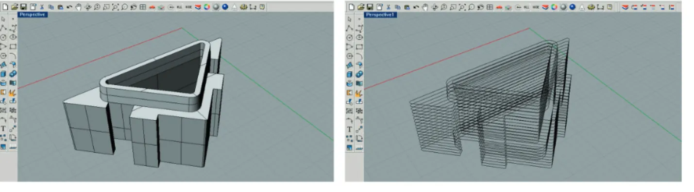
The process of making each concrete unit would be as follows. First, a digital three dimensional solid model would be drawn in the computer (Fig. 6.2.A). Second, utilizing an additive-layered fabrication machine (a ZCorp ZPrinter machine for these purposes) physical models of the cast would be made.
The fi rst feedback loop was then initialized and the physical model was tested against its initially proposed design and its relationship to the whole, or in this case the rest of the assembly (Fig. 6.2.B). If the physical plaster model met the requirements set forth by the qualifi cations, the digital three dimensional solid model was then translated into layers for fabrication sheets. The fi rst fabrication sheets were 1/3 scale models cut from 1/8” masonite on a 120 watt 2 axis laser cutter. The masonite layers (Fig. 6.2.C) were then assembled by
Figure 6.2.A
Figure 6.2.B
hand and cast using Rockite cement (Fig. 6.2.D).
[analyze]
Upon removal of the cast from the formwork both objects were sent for their second feedback loop. The cast was tested not only for its initially proposed design and relationship to the assembly but also by the fabrication process by testing its quality. The formwork was also tested by the fabrication process through its ability or inability to make a successful cast, the quality of the cast, its time effectiveness (which leads to cost), and its effi ciency or the reusability of the formwork.
[improve]
The element of the analysis which is least successful was then studied and methods in which to improve its performance were designed.
[repeat]
Once a method for improvement had been developed it was redrawn as a digital three dimensional solid model and the process was repeated again. This process took as many times as necessary until the results of the analysis were met or exceeded all qualifi cations set forth.
6.3 Formwork 1
[design]
The anticipated shape of the casting was fi rst constructed in a three-dimensional computer model comprised of closed poly surfaces. Horizontal contour lines were then arrayed throughout the model at the interval of the thickness of the formwork material. These contour lines of the positive model were then extracted and placed onto identical boxes with alignment holes. Partition lines were then added manually to assist in the release of each layer.
Figure 6.3.A
[model]
The formwork sheets were cut from 1/8” masonite using a 120W 2 axis universal laser cutter. Alignment bolts (1⁄4”) were added to precisely hold the layers together during casting.
[procedure]
The cast was performed using Rockite Cement mix. Due to the relative thinness of the walls a low aggregate material with a high rate of viscosity was required.
[results]
1. Overall, the fi rst cast utilizing negative layer fabrication
Figure 6.3.D Figure 6.3.C
proved to be extremely successful in terms of its accuracy, tolerance, effi ciency and resolution.
2. However, the release of the individual layers proved to be somewhat diffi cult in terms of ‘sticking’ and ‘locking’ and the interior section had to be drilled out for its removal.
3. Splitting the ring layers into half pieces with partition lines was helpful but problems existed primarily around the integrated dovetail connectors.
Initial Assembly 38 minutes
Disassembly and Cast Removal 51 minutes
6.4 Formwork 2
[design]
The primary purpose of the design modifi cations was to fi rst increase the effectiveness of the layer removals by making sure pieces could be removed quickly with ease and without damage. Second, methods for increasing the speed of assembling and dissembling in order to decrease the amount of human effort required was critical to make the formwork a cost viable option.
The computer model was edited and a draft angle was added to the interior to assist in the removal of those layers. The digital model was then contoured and added to the cut sheets in the same method as Formwork 1.
[model] Figure 6.4.A
Formwork sheets were labeled and registration marks were added to assist the assembly and disassembly time. Also, the partition lines were altered to break the rings at the point of the integrated connections.
[procedure]
Labeling each layer by its typology (base, bottom layers, middle layer, top layers & top) and number (distinguishing alternating partition lines) drastically improved assembly time. Pieces could be quickly arranged by their type and then ordered by their number. The registration marks quickly verifi ed that the layer was rotated in the correction direction. Casting again occurred with Rockite Cement with a high rate of viscosity. After setting for approximately 1 hour the pins were slid out and the layers removed.
[results]
1. The new partition lines located at the integrated dovetail connections was an improvement but still did not provide the desired ease and speed.
2. Providing a draft angle and hollowing the interior layers was much more effective. They could be removed without damage.
3. Although ease of removal and speed of assembly and disassembly was improved it seemed apparent that more improvements could be made.
Initial Assembly 19 minutes
Disassembly and Cast Removal 14 minutes
Formwork Reassembly 12 minutes
6.5 Formwork 3
[design]
After the results of Formwork 2 the main concern was to layout the layers in such a way that they would essentially “fall off” when being removed from the cast. The female dovetail integrated connection proved to be the most diffi cult section of layers to remove. Various layout concepts of the partition lines were drawn and analyzed. Up until this point every formwork was a one time only cast. Another intention of this formwork was to see how many casts could be executed before the model broke down to the point beyond reusability.
[model] Figure 6.5.A
The same formwork cut sheets from Formwork 2 where utilized with the labels and registration marks. However, the partition lines were edited and subdivided at the integrated connections as shown.
[procedure]
Increasing each layer from 3 parts to 5 parts also increased the amount of time required for assembly. The model formwork was assembled, cast and disassembled 3 times.
[results]
1. Although increasing the number of pieces in each layer increased the assembly time this was overcome by the increased effi ciency in removing the formwork from the casting and proved to be successful.
2. The fi rst 2 castings with the formwork proved successful. However, by the third casting the masonite had started to break down and weaken. This caused an increased “sticking” between the formwork and cast. Although this information was useful it was diffi cult to determine the long term viability because the actual anticipated formwork material was to be 1⁄2” plywood.
Initial Assembly 23 minutes
Disassembly and Cast Removal 7 minutes
Formwork Reassembly 14 minutes
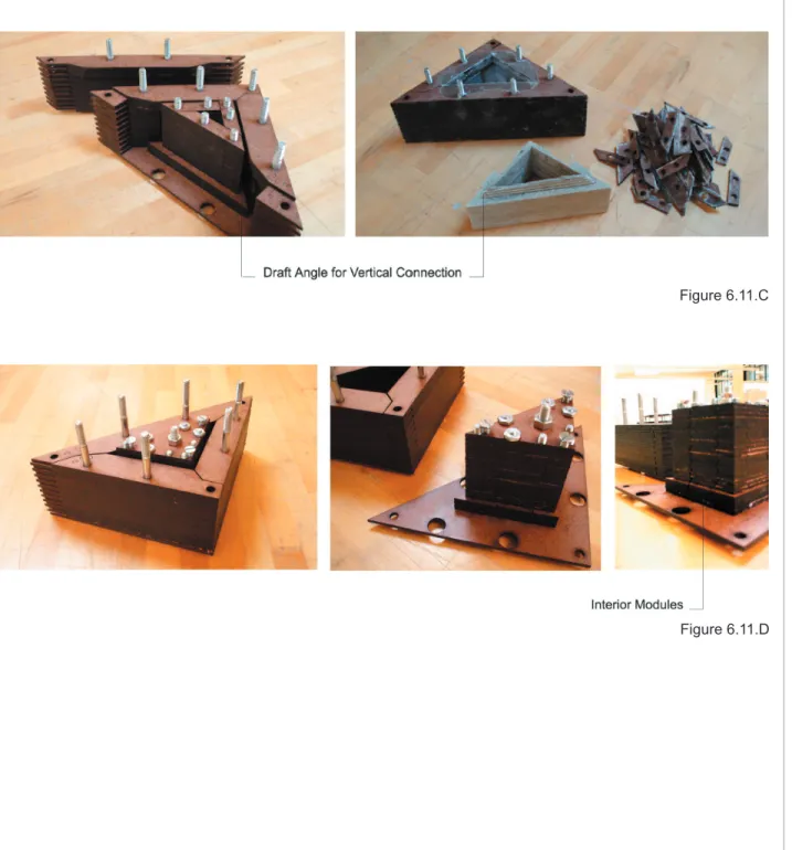
6.6 Formwork 4
[design]
After realizing that 3 castings per formwork would not offer a viable solution for mass customized rapidly generated formwork alternative materials were selected as possible design explorations.
Acrylic was chosen for its ability to resist water penetration and availability in sheet product form.
[model]
The model was constructed from 1/8” acrylic sheets utilizing the same formwork cut sheets from Formwork 3. The amount of acrylic required is approximately 10 times the cost when compared to
Figure 6.6.A
masonite. Cutting the formwork sheets also required more time when compared to masonite because the laser cutter needed to make 3 full passes per sheet in lieu of just 1 with masonite.
[procedure]
Although the model was assembled in the same way as previous formworks, more care had to be taken because of the brittleness of the material and its ability to easily crack. Again, the model was cast with Rockite and set for about an hour.
[results]
1. Because of the density of the material, if the layers where not heavily compressed together concrete was able to slide in between layers locking the formwork & cast together as well as decreasing the resolution of the fi nished casting. 2. The brittleness also became problematic during cast
removal. Its inability to fl ex made it diffi cult to remove pieces without breaking them. It also became apparent that the 4 sided units were weaker in the corners.
3. Although the acrylic is nearly impenetrable to water its density and brittleness & cost disadvantages far outweigh its usefulness as a possible formwork material and therefore was decided to no longer peruse it.
Initial Assembly 35 minutes
Disassembly and Cast Removal 28 minutes
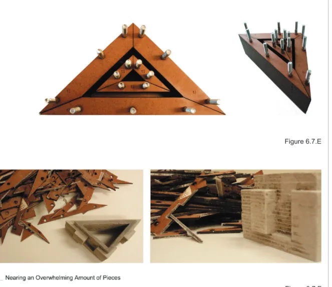
6.7 Formwork 5
[design]
Since the negative layer fabrication had yielded some success it was decided to initiate all feedback loops in the fabrication process diagram. Several critical design decisions were made.
First, it was realized that the 4-sided tube profi le might not be the ideal shape for several reasons. Four sided objects have an inherent instability due to high amounts of moment forces in the corners when shear and lateral stresses are applied (See Formwork 4 Results). Also, when several blocks were assembled together it was diffi cult to achieve an air and moisture tight seal between them without an additional material such as mortar or silicon due to the slight variations in the concrete fi nish.
Next, although dovetail connections are commonly used method of joining 2 pieces of wood together it does not translate well to concrete. Concrete at small scales does not make acute angles very well because of its lack of tensile strength. Also, the expansion and shrinking during the hydration process causes minuet variations in the tolerance which make tight uniform connections diffi cult to achieve.
Figure 6.7.B Figure 6.7.A
For the above reasons triangular shaped unit blocks with keyed connections where designed and analyzed. Triangle shapes where thought to be much more stable and when used in a alternating pattern could provide a better-sealed enclosure. Keyed connections where hypothesized to be much easier to cast and assemble then dovetail connections and would provide a “locked assembly” due to their angled geometry and redundancy of units.
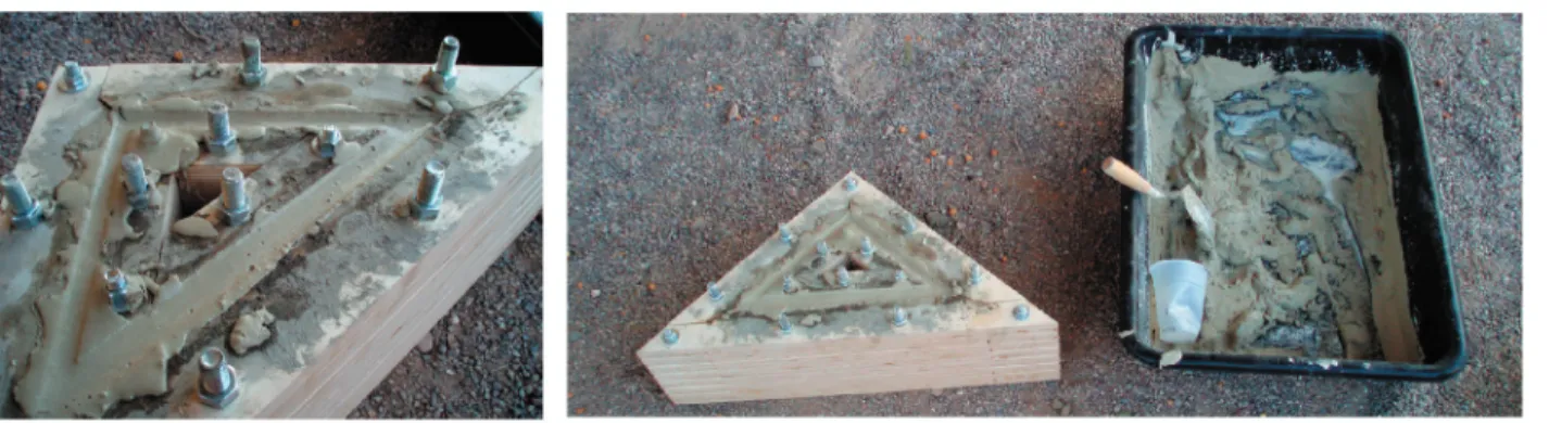
[model]
A positive 3 dimensional computer model was constructed and the contoured profi les extracted.
[procedure]
Formwork cut sheets were laid out and partition lines where added in a similar manner to previous models. The method of casting was similar to previous casts.
Figure 6.7.D Figure 6.7.C Figure 6.7.C