HAL Id: hal-01318076
https://hal.archives-ouvertes.fr/hal-01318076
Submitted on 19 May 2016
HAL is a multi-disciplinary open access
archive for the deposit and dissemination of
sci-entific research documents, whether they are
pub-lished or not. The documents may come from
L’archive ouverte pluridisciplinaire HAL, est
destinée au dépôt et à la diffusion de documents
scientifiques de niveau recherche, publiés ou non,
émanant des établissements d’enseignement et de
Stacking denoising auto-encoders in a deep network to
segment the brainstem on MRI in brain cancer patients:
a clinical study
Jose Dolz, Nacim Betrouni, Mathilde Quidet, Dris Kharroubi, Henri A. Leroy,
Nicolas Reyns, Laurent Massoptier, Maximilien Vermandel
To cite this version:
Jose Dolz, Nacim Betrouni, Mathilde Quidet, Dris Kharroubi, Henri A. Leroy, et al..
Stack-ing denoisStack-ing auto-encoders in a deep network to segment the brainstem on MRI in brain
can-cer patients:
a clinical study.
Computerized Medical Imaging and Graphics, Elsevier, 2016,
�10.1016/j.compmedimag.2016.03.003�. �hal-01318076�
Personal
Cop
y
of
the
Author
Stacking denoising auto-encoders in a deep network to
segment the brainstem on MRI in brain cancer
patients: a clinical study
Jose Dolza,b,∗, Nacim Betrounib, Mathilde Quidetb, Dris Kharroubib, Henri A. Leroyb,c, Nicolas Reynsb,c, Laurent Massoptiera, Maximilien Vermandelb,c
aAQUILAB, Loos-les-Lille, France
bUniv. Lille, Inserm, CHU Lille, U1189 - ONCO-THAI - Image Assisted Laser Therapy
for Oncology, F-59000 Lille, France
cNeurosurgery Department, University Hospital Lille, Lille, France
Abstract
Delineation of organs at risk (OARs) is a crucial step in surgical and treatment planning in brain cancer, where precise OARs volume delineation is required. However, this task is still often manually performed, which is time-consuming and prone to observer variability. To tackle these issues a deep learning approach based on stacking denoising auto-encoders has been proposed to segment the brainstem on magnetic resonance images in brain cancer context. Addition-ally to classical features used in machine learning to segment brain structures, two new features are suggested. Four experts participated in this study by segmenting the brainstem on 9 patients who underwent radiosurgery. Analysis of variance on shape and volume similarity metrics indicated that there were significant differences (p<0.05) between the groups of manual annotations and automatic segmentations. Experimental evaluation also showed an overlapping higher than 90% with respect to the ground truth. These results are compara-ble, and often higher, to those of the state of the art segmentation methods but with a considerably reduction of the segmentation time.
Keywords: Deep learning, MRI segmentation, brain cancer, machine learning.
1. Introduction
Cancer is a leading cause of death and disability worldwide, accounting for 14.1 million of new cancer cases and 8.2 million deaths in 2012 [1]. Among available techniques to treat brain tumors, radiotherapy and radio surgery have often become the selected treatment, especially when others techniques such
5
as surgery or chemotherapy might not be applicable. To constrain the risk of severe toxicity of critical brain structures, i.e. the organs at risk (OARs),
Personal
Cop
y
of
the
Author
the volume measurements and the localization of these structures are required.Among available image modalities, magnetic resonance imaging (MRI) images are extensively used to segment most of the OARs, which is performed mostly
10
manually nowadays.
However, manual delineation of large brain structures, such as the brainstem, could be prohibitively time-consuming, and could never be reproducible during clinical routines [2, 3], leading to substantial inconsistency in the segmentation. Particularly, in the case of the brainstem, variability on delineation is especially
15
notorious in the area where the brainstem meets with the cerebellum in the lower pons, and where no significant contrast boundary is present. Thus, image segmentation has become a central part in the radiation treatment planning (RTP), being often a limiting step of it. Therefore, automatic or semi-automatic segmentation algorithms are highly recommended in order to surmount such
20
disadvantages.
Segmentation of brain structures have been mainly approached by using
atlas-based methods [4, 5]. Although good performance has been reported,
evaluation of these methods has been made on control and on several mental disorders patients, such as Schizophrenia or Alzheimer. However, in brain
can-25
cer context, the presence of tumors may deform other structures and appear together with edema that changes intensity properties of the nearby region, making the segmentation more challenging. To evaluate the performance of atlas-based approaches to segment the brainstem, among other structures, in such situations, some work have been recently presented in the context of brain
30
cancer treatment [2, 3, 6]. In [2], a large study that engaged 8 experts and in-cluded 20 patients reported mean Dice similarity coefficient (DSC) respect to the ground truth generated of nearly 0.85. Euclidean average maximum distances ranged from - to + 5.4 mm (inside and outside). Similar to this work, in [3], an atlas-based segmentation was evaluated on 6 patients and compared to 7 expert
35
delineations. Comparison between experts and automatic results showed that brainstem segmentation volume generated by the automatic approach lay in 5 out of 6 cases between the variations of the experts, with a volume underesti-mation ranging from -14% to -2% in these patients. In the work of Isambert et al. [6], brainstem automatic contours were accepted for clinical routine with a
40
volume underestimation of -15% with respect to the manual segmentation and mean DSC of 0.85 ranging from 0.8 to 0.88. Although the brainstem has been often successfully segmented, with DSC values typically greater than 0.8, seg-mentation time reported has been always above several minutes. In addition to time constraints derived from the registration step, atlas-based methods
re-45
quire large variation on the atlases to capture anatomical variability in target patients.
To overcome difficulties of atlas-based approaches, we considered the use of denoising auto-encoders in the presented work. Deep learning has already been used to segment some tissue or organs in the medical domain others than the
50
brainstem [7, 8]. In these approaches, two or three-dimensional image patches are commonly fed into the deep network, which unsupervisedly learns the best features representation of the given patches. Computed neurons’ weights are
Personal
Cop
y
of
the
Author
then re-fined during a second supervised step. However, valuable informationinherited from classical machine learning approaches to segment brain structures
55
is not included in these input vectors. This knowledge may come in the form of likelihood voxel values or voxel location, for example, which is greatly useful to segment structures that share similar intensity properties.
In the present work, we propose a deep neural network formed by stacking de-noising auto-encoders (SDAE) as alternative to atlas-based methods to segment
60
the brainstem. Additionally, we compare the results with a well-known ma-chine learning classifier, support vector mama-chines (SVM). Furthermore, instead of using patches from single or multi-modality MR images, we use hand-crafted features as input of the network. Lastly, as extension to features typically em-ployed in machine learning approaches to segment brain structures [9, 10, 11],
65
we propose the inclusion of two new features in the features vector of the classi-fier when segmenting the brainstem. Our main contribution is, therefore, a new and practical application of SDAE, which recently produced outstanding results in solving some medical image problems, such as classification or segmentation.
2. Methods and materials
70
2.1. Features used in the classification
The most influencing factor in realizing a classifier with high generalization ability is the set of features used. A poor selection of the features to be used in the classifier may lead to unsatisfactory results. Intensity based approaches have been largely employed to segment objects of interest in the medical field.
75
Nevertheless, image intensity information solely is not good enough for distin-guishing different subcortical structures since most of them share similar inten-sity patterns in MRI. To address such problem, in learning based segmentation methods, more discriminative features are often extracted from MRI [9, 10, 11]. In addition to image intensity values (IIV) of the neighboring voxels, spatial
80
and probabilistic information is often used in the creation of a classifier. Texture information, i.e. IIV related information, can be captured in many ways. For instance, Powell et al. [9] captured texture information by using 8 IIV along the largest gradient, including the voxel under examination. Additionally, a probabilistic map, IIVs along each of the three orthogonal axes and the
prob-85
ability of being part of a particular structure were used as features for each sample. In [10], a slightly modified input vector was adapted to increase the performance of a learning-based scheme. In their work, a modified spatial loca-tion of the spherical coordinates of the voxel v and a neighborhood connecloca-tion based on gradient descent were used. While the former aided to reflect
sym-90
metry of brain, the latter was used for directional consistency. More recently, in [11], different IIVs configurations were compared to segment the brainstem, in addition to probability values and spherical coordinates of the voxel under examination. Configurations proposed in this work included cubic patches of different sizes, orthogonal crosses and, as in [9], voxels along the direction of
95
Personal
Cop
y
of
the
Author
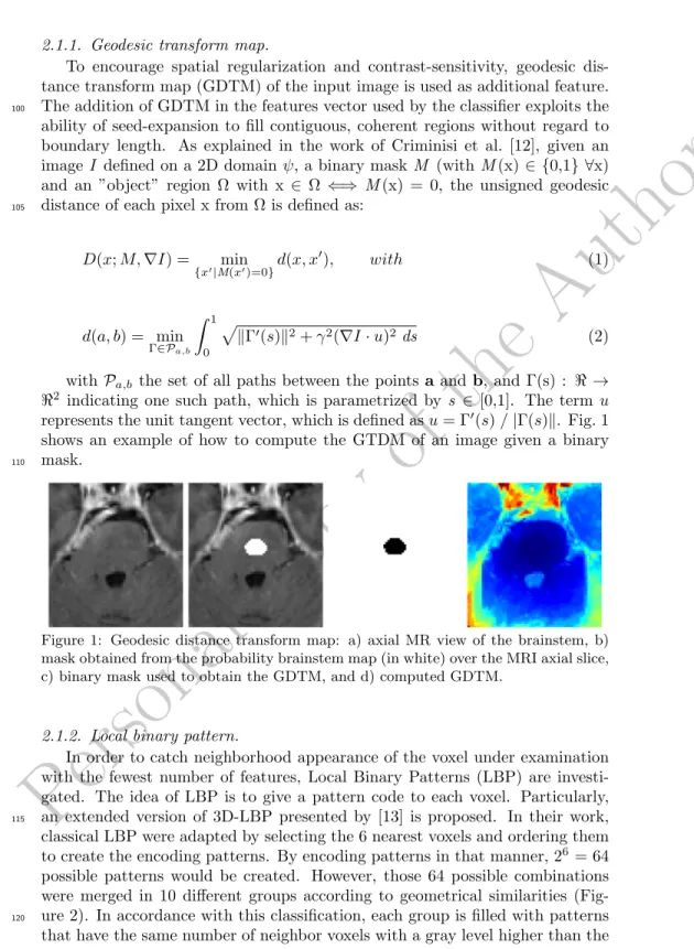
2.1.1. Geodesic transform map.To encourage spatial regularization and contrast-sensitivity, geodesic dis-tance transform map (GDTM) of the input image is used as additional feature. The addition of GDTM in the features vector used by the classifier exploits the
100
ability of seed-expansion to fill contiguous, coherent regions without regard to boundary length. As explained in the work of Criminisi et al. [12], given an image I defined on a 2D domain ψ, a binary mask M (with M (x) ∈ {0,1} ∀x) and an ”object” region Ω with x ∈ Ω ⇐⇒ M (x) = 0, the unsigned geodesic distance of each pixel x from Ω is defined as:
105 D(x; M, ∇I) = min {x0|M(x0)=0}d(x, x 0), with (1) d(a, b) = min Γ∈Pa,b Z 1 0 pkΓ0(s)k2+ γ2(∇I · u)2ds (2)
with Pa,b the set of all paths between the points a and b, and Γ(s) : < → <2 indicating one such path, which is parametrized by s ∈ [0,1]. The term u represents the unit tangent vector, which is defined as u = Γ0(s) / |Γ(s)k. Fig. 1 shows an example of how to compute the GTDM of an image given a binary mask.
110
Figure 1: Geodesic distance transform map: a) axial MR view of the brainstem, b) mask obtained from the probability brainstem map (in white) over the MRI axial slice, c) binary mask used to obtain the GDTM, and d) computed GDTM.
2.1.2. Local binary pattern.
In order to catch neighborhood appearance of the voxel under examination with the fewest number of features, Local Binary Patterns (LBP) are investi-gated. The idea of LBP is to give a pattern code to each voxel. Particularly, an extended version of 3D-LBP presented by [13] is proposed. In their work,
115
classical LBP were adapted by selecting the 6 nearest voxels and ordering them to create the encoding patterns. By encoding patterns in that manner, 26 = 64 possible patterns would be created. However, those 64 possible combinations were merged in 10 different groups according to geometrical similarities (Fig-ure 2). In accordance with this classification, each group is filled with patterns
120
Personal
Cop
y
of
the
Author
central voxel c. Thus, rotation invariance in each group is kept. These groupsare defined with (Figure 2,b):
card(c) = P −1 X i=0 s(gi− gc), with s(x) = ( 1 if x ≥ 0 0 else (3)
where P = 6 is the number of neighboring voxels and R=1 or R=2 the distance between central voxel c and its neighbors i. By using R =1,2 micro
125
and macrostructure appearance of the texture are captured in the 3D-LBP. In equation 3, card(c) gives the number of neighbors with a higher gray level than the central voxel c.
(a) (b)
Figure 2: (a). Merging the 64 possible patterns into 10 groups. Number of different patterns for each group is indicated in brackets.(b).Definition of the 10 groups of patterns[13].
In addition to the encoded value for the 3D patch structure proposed by [13], an additional texture value is included. Let ghighthe gray values that are higher than the gray value of the center voxel c in the 3D-LPB (Figure 2). Similarly, let’s denote glow to the gray values that are lower than the gray value of the center voxel c in the 3D-LPB. Then, the texture value added to the encoded structure value is defined as:
T extureval= mean m X
i=0
ghigh(i) − mean n X
i=0
glow(i) (4)
where m and n are the number of neighboring voxels with higher and lower values than the center voxel c, respectively. Thus, the introduction of the
3D-130
LBP in the features vector will lead to 4 new features: 3D-LBP and Textureval for R = 1 and 2.
2.1.3. Composition of the input features vector.
Different combinations of intensity values of the neighborhood of a given voxel and its effect on the segmentation was already investigated in [11]. In
135
that work, the intensity value of the voxel under investigation and the intensity values of the 8 voxel along the direction of maximum gradient reported the best trade-off in terms of segmentation similarity and computational cost. Therefore,
Personal
Cop
y
of
the
Author
this configuration is used in the present work to capture intensity informationfrom the MRI image. Additionally, to better understand the pattern of each
140
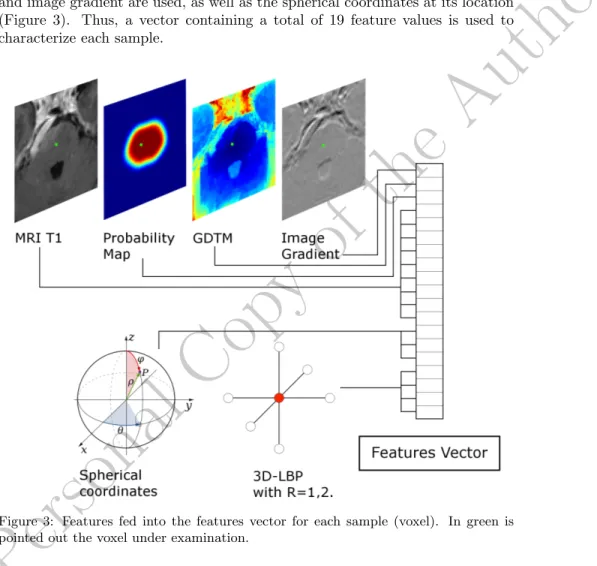
voxel with respect to its neighborhood, while feeding the minimum amount of information into the features vector, the 3D-LPB introduced in section 2.1.2 is used. Its use leads to 2 values, one for the pattern and one for the texture, at each of the two radius used (R=1,2). To complete the features vector, the value at the voxel location of the probability map, geodesic distance transform map
145
and image gradient are used, as well as the spherical coordinates at its location (Figure 3). Thus, a vector containing a total of 19 feature values is used to characterize each sample.
Figure 3: Features fed into the features vector for each sample (voxel). In green is pointed out the voxel under examination.
In order to provide a robust classifier, features that compose the input array must show discriminative power. This means that each of these features must
150
be complementary to the others, providing additional information that helps in the classification task. To visually demonstrate that features incorporated into the features array are uncorrelated, correlations between some pairs of features are plotted (Fig. 4). Image intensity is combined with three of the proposed features -probability map, geodesic transform map and image gradient-.
Personal
Cop
y
of
the
Author
Thus, we investigate whether they bring valuable information to the knowledgeprovided by intensity values to perform the classification. Analysis conducted on each pair of features showed that including them, in addition to intensity information, helps for distinguishing between classes.
−1 −0.8 −0.6 −0.4 −0.2 0 0.2 0.4 0.6 0.8 1 −1 −0.8 −0.6 −0.4 −0.2 0 0.2 0.4 0.6 0.8 1
Probability Map value
Intensity value
Intensity value vs. Probability Map value
Brainstem Not Brainstem a −1 −0.8 −0.6 −0.4 −0.2 0 0.2 0.4 0.6 0.8 1 −1 −0.8 −0.6 −0.4 −0.2 0 0.2 0.4 0.6 0.8 1
Geodesic Distance Map value
Intensity value
Intensity value vs. Geodesic Distance Map value
Brainstem Not Brainstem b −1 −0.8 −0.6 −0.4 −0.2 0 0.2 0.4 0.6 0.8 1 −1 −0.8 −0.6 −0.4 −0.2 0 0.2 0.4 0.6 0.8 1 Gradient value Intensity value
Intensity value vs. Gradient value
Brainstem Not Brainstem
c
Figure 4: Decision boundary plots for two classes by using solely intensity information and : a) probability map values, b) geodesic distances map values and c) gradient values.
2.2. Support vector machines
160
Support vector machines (SVM), often called kernel-based methods, have been extensively studied and applied to several pattern classification and func-tion approximafunc-tion problems. Basically, the main idea behind SVM is to find the largest margin hyperplane that separates two classes. The minimal distance from the separating hyperplane to the closest training example is called
mar-165
gin. Thus, the optimal hyperplane is the one providing the maximal margin, which represents the largest separation between the classes. This will be the line such that the distances from the closest point in each of the two groups will be farthest away. The training samples that lie on the margin are referred as support vectors, and conceptually are the most difficult data points to classify.
170
Therefore, support vectors define the location of the separating hyperplane, be-ing located at the boundary of their respective classes. By employbe-ing kernel transformations to map the objects from their original space into a higher di-mensional feature space [14], SVM can separate objects which are not linearly separable (Figure 5). Their good generalization ability and their capability to
175
successfully classify non-linearly separable data have led to a growing interest on them for classification problems.
2.3. Deep Learning based classification scheme
Classification problem is solved in this work by using deep learning. This technique learns hierarchical correlations between feature representations in a
180
given dataset through a semi-supervised learning approach [15]. Hence, the proposed approach follows a hybrid architecture which unsupervisedly learns the features’ representation of the hand-crafted features followed by a supervised fine tuning of the parameters of the deep network.
Personal
Cop
y
of
the
Author
Figure 5: SVM and hyperplane. Mapping features into a higher dimensionality maymake the classification simpler.
The deep network used in the proposed classification scheme is formed by
185
stacking DAEs (Fig. 6). Weights between layers of the network are initially learned via the unsupervised pre-training step (Sec. 2.3.1). Once all the weights of the network are unsupervisedly computed, a supervised refinement is carried out by using the labeled classes, and final values of the network’ weights are updated (Sec. 2.3.2).
190
2.3.1. Unsupervised pre-training of DAEs
Classical auto-encoders (AE) have been recently developed in the deep learn-ing literature in different forms [16]. In its simplest representation, an AE is
formed by two components: an encoder h(·) that maps the input x ∈ Rd to
some hidden representation h(x) ∈ Rdh , and a decoder g(·), which maps the
195
hidden representation back to a reconstructed version of the input x, so that g(h(x)) ≈ x. Therefore, an AE is trained to minimize the discrepancy between the data and its reconstruction. This discrepancy represents the difference be-tween the actual output vector and the expected output vector that is the same as the input vector. As a result, AEs offer a method to automatically learn
200
features from unlabeled data, allowing for unsupervised learning.
One serious potential issue when working with AE is that if there is no other constraint besides minimizing the reconstruction error, then an AE with n inputs and an encoding of dimension at least n could potentially just learn the identity function, for which many encodings would be useless, leading to just
205
copy the input. That means that an AE would not differentiate test examples from other input configurations. There are different ways that an AE with more hidden units than inputs could be prevented from learning the identity, and still capture some valuable information about the input in its hidden representation.
Personal
Cop
y
of
the
Author
Figure 6: Deep network architecture constructred by stacking denoising autoencodersin the proposed approach.
Adding randomness in the transformation from input to reconstruction is one
210
option, which is exploited in Denoising Auto-Encoders (DAEs) [16, 17]. The denoising auto-encoder (DAE) is typically implemented as a one-hidden-layer neural network which is trained to reconstruct a data point x ∈ <D from its corrupted version ˜x [17]. This leads to a partially destroyed version ˜x by means of a stochastic mapping ˜x ∼ qD(˜x|x). Therefore, to convert an AE class
215
into a DAE class, only adding a stochastic corruption step that modifies the input is required, which can be done in many ways. For example, in [17], the stochastic corruption process consists in randomly setting some of the inputs to zero. Several DAEs can be stacked to form a deep network by feeding the hidden representation of the DAE found on the layer below as input to the
220
current layer [16]. The unsupervised pre-training of such architecture is done greedily, i.e. one layer at a time. Each layer is trained as a DAE by minimizing the reconstruction of its input. Once the first k layers are trained, the (k +1)th layer can be trained because the latent representation from the layer below can be then computed.
225
In our network, DAEs are stacked to form the intermediate layers of the deep network (See Figure 6). More specifically, 2 hidden layers composed by 100 and 19 units, respectively, are used. During the unsupervised pre-training, the weights vectors {W1, W2} are initially learned. Denoising corruption level for the DAEs is set to 0.5, since a value of 50% of noise level has already been
230
proved to perform well in other problems [16]. 2.3.2. Supervised fine-tuning of the deep network
Afterwards, when all layers have been pre-trained, the network goes through a second stage of training called fine-tuning, where prediction error is minimized
on a supervised task. Weights vectors {W1, W2} are already known from the
Personal
Cop
y
of
the
Author
previous step. The weights {W3} are now randomly initialized and convergenceof the deep network is achieved via supervised learning, using the target class. During this process, weights {W1, W2} are updated to tune the entire network. The hope is that the unsupervised initialization in a greedy layer-wise fashion has put the parameters of all the layers in a region of parameter space from
240
which a good local optimum can be reached by local descent.
Following the same architecture than in the unsupervised pre-training, two hidden layers of DAEs are used, with the same number of units than before. At the end of the last layer of DAEs a softmax regression layer is used as output with the sigmoid function as activation function. Mini-batch learning is followed
245
during both unsupervised pre-training of DAEs and supervised fine-tuning of the entire network.
2.4. Study design and experiment set-up
2.4.1. Dataset
Image segmentation in the medical domain lacks from a universal known
250
ground truth. Therefore, to validate segmentation approaches in clinical con-text, a number of observers and target patients that provide a good statistical analysis is required. Accordingly, this study has been designed to quantify vari-ation among clinicians in delineating the brainstem and to assess our proposed classification scheme in this context. MRI data from 9 patients who
under-255
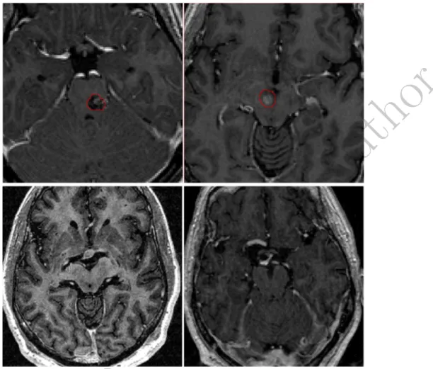
went Leksell Gamma Knife Radiosurgery were used for training and leave one out cross validation. Pathologies in this dataset included trigeminal neuralgia, metastases, and brainstem cavernoma (See figure 7 for some visual examples). For each patient, the brainstem was manually delineated by four observers: two neurosurgeons, one physician and one medical physicist. All of them were
260
trained and qualified for radiosurgery delineation. Protocol for delineation was described before contouring session. The brainstem was delineated from cerebel-lar peduncle to occipital hole including the aqueduct of Sylvius. From manual segmentations of each patient a ground truth was generated by using majority voting rule with a threshold fixed at 75% of experts agreement. This ground
265
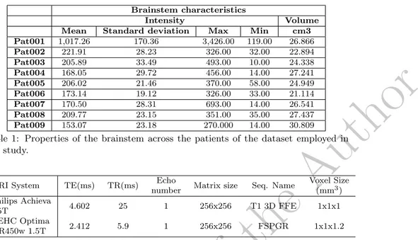
truth was used to analyze deviations between the observers delineations, as well as the performance of the presented automatic approach. Properties of
brain-stem appearance across the 9 patients is shown in Table 1. Artiview 3.0R
(Aquilab) was used after a training session to achieve Dicom RT contouring structures. Average time of manual contouring was 20.2 min (SD: 10.8 min).
270
Two different MRI facilities were used to acquire images according to the ra-diosurgery planning protocol (Table 2). Particularly, MR T1 sequences were employed in this work.
In the proposed approach, and as in [9], before any process, MRI T1 images were spatially aligned such that the anterior commissure and posterior
commis-275
sure (AC−PC) line was horizontally oriented in the sagittal plane, and the inter hemispheric fissure was aligned on the two other axes.
Personal
Cop
y
of
the
Author
Figure 7: Some examples of images contained in the database employed in this work. While in some cases the tumor is inside the brainstem and may change the shape and intensity properties of the brainstem (top-row), in other brain cancer cases, tumors do not affect the brainstem properties.
2.4.2. Evaluation
Evaluation methods have lacked consensus as to comparison metrics. Since each metric yields different information, their choice is important and must be
280
considered in the appropriate context. Although volume-based metrics, such as DSC [18], have been broadly used to compare volume similarities, they are fairly insensitive to edge differences when those differences have a small impact on the overall volume. Therefore, two segmentations with high degree of spa-tial overlapping may exhibit clinically relevant differences at the edges. As a
285
consequence, volume-based −i.e. DSC and percentage volume difference− and distance-based −i.e. Hausdorff distance− metrics are used to evaluate the seg-mentation results. Within-subjects analysis of variance (ANOVA), also referred
Personal
Cop
y
of
the
Author
Brainstem characteristics Intensity VolumeMean Standard deviation Max Min cm3
Pat001 1,017.26 170.36 3,426.00 119.00 26.866 Pat002 221.91 28.23 326.00 32.00 22.894 Pat003 205.89 33.49 493.00 10.00 24.338 Pat004 168.05 29.72 456.00 14.00 27.241 Pat005 206.02 21.46 370.00 58.00 24.949 Pat006 173.14 19.12 326.00 33.00 21.114 Pat007 170.50 28.31 693.00 14.00 26.541 Pat008 209.77 23.15 351.00 35.00 27.437 Pat009 153.07 23.18 270.000 14.00 30.809
Table 1: Properties of the brainstem across the patients of the dataset employed in this study.
MRI System TE(ms) TR(ms) Echo
number Matrix size Seq. Name
Voxel Size (mm3) Philips Achieva 1.5T 4.602 25 1 256x256 T1 3D FFE 1x1x1 GEHC Optima MR450w 1.5T 2.412 5.9 1 256x256 FSPGR 1x1x1.2
Table 2: Acquisition parameters on the 2 MRI devices.
to as repeated measures, on shape and volume similarity metrics followed by post-hoc comparisons (Bonferroni, p<0.05) were used to determine statistical
290
differences between the groups.
Our method was compared with Support vector machines (SVM) [14] using the features vector detailed in Figure 3 for each sample. This SVM configuration is referred as SVM2. To investigate the effect of the proposed features, the best IIV configuration suggested by [11] to segment the brainstem by using SVM was
295
used as second set of features, referred to as SVM1. This second set includes the features shown in Figure 3, with exception of the GDTM, image gradient and 3D-LBP related values. The reason to use SVM is that it represents one of the state-of-the-art machine learning methods for classification. Lastly, the deep learning-based classifier based on SDAE will be known simply as SDAE
300
and it will use the same features vector than SVM2. Once all the features to be used are extracted, and before training or testing, they are normalized to [−1, 1]. These features vectors represent the input of both the SVM and deep learning schemes.
All the implementation was done in MATLAB. To perform the SVM
clas-305
sification the library libsvm [19] was used. To map the features into higher-dimensionality spaces, a radial basis function (RBF) kernel was employed. To tune the other SVM parameters, as in the work of Dolz et al. [11], a grid search strategy was employed. Thus, values for SVM parameters -C and γ- were 7.5 and 3, respectively. Additionally, the implementation provided by Palm [20]
310
was used for the deep learning classification scheme. A workstation with 8GB RAM and Intel Xeon processor at 3.06 was employed.
Personal
Cop
y
of
the
Author
3. Results 3.1. Shape similarityThe Dice similarity coefficient (DSC) was calculated for the four manual
315
annotations and the three automatic methods. Mean DSC values for the four observers ranged from 0.84 to 0.90, with minimum and maximum values of 0.78
and 0.93 respectively. Reference SVM (SVM1) provided a mean DSC of 0.88.
On the other hand, whereas mean DSC for SVM with the proposed features was 0.91, the proposed deep learning based scheme reported a mean DSC of 0.92
320
(Fig. 8). The within-subjects ANOVA test conducted on the DSC of all the groups (p<0.05) indicated that there were significative differences among them. These differences were especially notorious on observers 1 and 4.
Obs.1 Obs.2 Obs.3 Obs.4 SVM 1 SVM 2 SDAE 0.8 0.82 0.84 0.86 0.88 0.9 0.92 0.94
Dice Similarity Coefficients
p−value < 0.0001 F−stat = 10.47
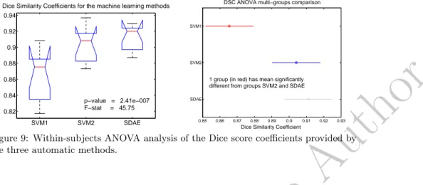
Figure 8: Segmentation DSC results for the observers and the automatic approaches. Particularly for the machine and deep learning based approaches, a second set of ANOVAs was conducted to evaluate statistical differences between
auto-325
matic methods. First, a within-subjects ANOVA (Figure 9, left) including the three methods indicated that there were significant differences between them. Therefore, at least one method significantly differed from the others (p<0.05). The post-hoc analysis (Bonferroni) confirmed the statistical differences between these three approaches (see Figure 9, right). Paired repeated measures ANOVAs
330
(Table 3) pointed out that, while approaches including the proposed features (SVM2 and SDAE) performed significantly better (p<0.05) than SVM1, no sig-nificant differences were found between them (p = 0.0811).
SVM1vs. SVM2 SVM1 vs. SDAE SVM2 vs. SDAE
p-value 0.0002 0.0001 0.0811
Table 3: Within-subjects ANOVA on DSC values between automatic segmentation approaches.
Results also showed that Hausdorff distances decreased in the classification schemes using both machine and deep learning techniques, in comparison with
335
Personal
Cop
y
of
the
Author
SVM1 SVM2 SDAE 0.82 0.84 0.86 0.88 0.9 0.92 0.94Dice Similarity Coefficients for the machine learning methods
p−value = 2.41e−007 F−stat = 45.75 0.85 0.86 0.87 0.88 0.89 0.9 0.91 0.92 0.93 SDAE SVM2 SVM1
DSC ANOVA multi−groups comparison
Dice Similarity Coefficient 1 group (in red) has mean significantly different from groups SVM2 and SDAE
Figure 9: Within-subjects ANOVA analysis of the Dice score coefficients provided by the three automatic methods.
features (SVM2 and SDAE) decreased more the Hausdorff distances than the
machine learning scheme used as reference, which did not include the suggested
features (SVM1). The within-subjects ANOVA test conducted on the Hausdorff
distances values indicated that, although less significative than in the case of
340
DSC, statistical differences between the groups existed. Again, these differences came overall from observer 1 and 4. Taking into account the Hausdorff distances measured only on the machine and deep learning based schemes, a p-value of 0.0353 was obtained. As in the case of DSC values, at least one method signif-icantly differed from the others (p<0.05). Paired repeated measures ANOVAs
345
(Table 4) indicated that method SVM1was statistically different from methods SVM2and SDAE (<0.05). Nevertheless, it failed to demonstrate a statistically significant difference between these two approaches (p = 0.7874).
Obs.1 Obs.2 Obs.3 Obs.4 SVM 1 SVM 2 SDAE 4 6 8 10 12 14 Hausdorff Distances (mm) p−value = 0.0128 F−stat = 3.06
Figure 10: Hausdorff distances meassured for the volume segmented by the observers and the automatic approaches.
Personal
Cop
y
of
the
Author
SVM1vs. SVM2 SVM1 vs. SDAE SVM2 vs. SDAE p-value 0.0067 0.0202 0.7874Table 4: Paired within-subjects ANOVA on Hausdorff distances between automatic segmentation approaches.
3.2. Volume similarity
Manual contours differed from the ground truth between 18.9% (Observer 2)
350
and 39.4% (Observer 4) as average (Table 5). In contrast, the three automatic approaches presented here largely decreased these volume differences, with a
mean difference of 7.2%, 4.0% and 3.1% for SVM1, SVM2 and SDAE,
respec-tively. Individual values for volume differences (%) are shown in Table 5 for all the patients contoured by the four observers and the three analyzed methods.
355
As it can be observed, classification schemes including the proposed features decreased the volume difference of automatic segmented volumes with respect to the reference ones.
Patient Volume difference (%)
Obs.1 Obs.2 Obs.3 Obs.4 SVM1 SVM2 SDAE
#1 40.7% 19.3% 20.6% 28.1% 5.5% 2.2% 4.8% #2 28.8% 34.9% 39.6% 32.4% 3.6% -1.9% 1.8% #3 24.1% 13.7% 29.3% 49.4% 3.8% 2.0% 0.8% #4 34.4% 19.8% 17.3% 41.6% -4.4% 5.2% 3.1% #5 18.7% 13.9% 15.5% 51.7% -8.2% -6.6% -3.4% #6 22.9% 19.6% 13.7% 32.6% -7.6% -3.5% -3.7% #7 33.3% 15.8% 25.3% 33.5% -2.5% -3.6% -3.1% #8 21.2% 15.9% 25.5% 47.6% -12.6% -5.5% 4.0% #9 40.6% 17.3% 25.9% 38.1% -16.2% -5.0% -3.2% Average 29.4% 18.9% 23.6% 39.4% 7.2% 4.0% 3.1% Std. Dev 8.3% 6.4% 8.0% 8.5% 4.6% 1.7% 1.2%
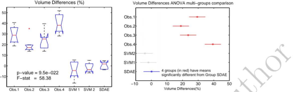
Table 5: Evaluation results (Volume difference (%)) of the manual contouring for the four observers, SVM and proposed approach with respect to the generated ground truth. The average represents the average of the absolute of volume difference values. A within-subjects ANOVA was performed over the volume differences values for the four observers and the three automatic contours (Figure 11). Visual
dif-360
ference between the groups of manual and automatic segmentations is confirmed by the p-value (<0.05) obtained in the ANOVA test. Because the p-value was less than the significance level of 0.05, the null hypothesis can be rejected and we can conclude that some of the groups have statistically significant differences on their mean values. The post-hoc analysis (Bonferroni) is shown Figure 11 on
365
the right. It confirms that significant differences came from the groups formed by the 4 observers in one side, and by the automatic contours in the other side. Repeated measures ANOVA tests between volume differences and the ground truth was conducted to individually compare the volumes. Computed p-values for the automatic segmentation methods were greater than 0.05, particularly in
370
Personal
Cop
y
of
the
Author
Obs.1 Obs.2 Obs.3 Obs.4 SVM 1 SVM 2 SDAE
−10 0 10 20 30 40 50 Volume Differences (%) p−value = 9.5e−022 F−stat = 58.38 −10 0 10 20 30 40 50 SDAE SVM1 SVM2 Obs.4 Obs.3 Obs.2 Obs.1 Volume Differences(%)
Volume Differences ANOVA multi−groups comparison
4 groups (in red) have means significantly different from Group SDAE
Figure 11: Results of the within-subjects ANOVA test conducted on the volume dif-ference values for the four manual contours and the three automatic methods. On the left, mean volume differences and deviations are shown. On the right, the ANOVA multi-group comparison is displayed, where the automatic method SDAE is selected as reference of the comparison.
significant similarity between automatically segmented volumes and generated ground truth volumes, notably for the SDAE based scheme.
SVM1vs. GroundTruth SVM2 vs. GroundTruth SDAE vs. GroundTruth
p-value 0.1175 0.1841 0.4584
Table 6: Repeated measures ANOVA on volume differences values between automatic segmentation approaches and the ground truth.
Segmentation result on a given patient can be visually seen in Fig. 12. On this figure, both manual and automatic contours are displayed, in addition to
375
the ground truth. It can be observed that contours generated by the automatic approach lie on the variability of the four experts.
3.3. Classification time
Regarding the segmentation time of the automatic approaches, while the features extraction time was the same for all the approaches, classification time
380
differed between the SVM and SDAE based schemes. Features extraction pro-cess was done in around 15 seconds as average for each volume. Concerning the segmentation, layouts based on SVM reported a mean classification time close to 25 seconds for the whole volume. Contrary, the deep learning-based scheme performed the task in 0.36 seconds as average.
385
4. Discussion
A deep learning-based classification scheme formed by stacking denoising auto-encoders has been proposed in this work to segment the brainstem. It has been compared with a machine learning approach widely and successfully used for classification, i.e. SVM. Additionally to traditional spatial and intensity
390
Personal
Cop
y
of
the
Author
distance transform map, and a modified version of a 3D local binary patternhas been proposed and evaluated.
The most influencing factor in realizing a classifier with high generalization ability is the set of features used. A poor selection of the features to be used
395
in the classifier may lead to unsatisfactory results. Ideal features should bring a high discriminative power to the classifier. Features proposed in this work have different nature. While some of them come from pure image intensity properties, some others provide spatial or texture knowledge. Thus, they are ’a priori’ uncorrelated. To visually demonstrated uncorrelation between some of
400
these features, classification tests were conducted by using only pairs of features (See fig. 4). Although it was not presented, combination of all of these features together improves the classification task, creating a classifier with higher dis-criminative power. This improvement on classification is reflected in the results section.
405
Statistical analysis indicated that there were significant differences between the automatic (machine and deep learning based) schemes and the manual de-lineations made by the four experts. In addition, the ANOVA tests performed between the machine and deep learning based approaches, suggested that dif-ferences between them were statistically significatives on the DSC evaluation.
410
These differences were particularly important in the classification schemes that included the proposed features. Although differences were less significative in the rest of the similarity metrics, results showed that our deep learning clas-sification scheme performed better than the other machine learning based ap-proaches. In terms of segmentation time, while features extraction was equal
415
in all the approaches, classification time reported by the deep learning scheme was approximately 70 times faster than SVM based scheme. Consequently, the proposed deep learning architecture demonstrated a significant gain in the per-formance of the brainstem segmentation on MRI, outperforming the widely used SVM approach.
420
Even though the presented work is not pioneering on the evaluation of auto-matic segmentation of the brainstem, among others, in the context of radiation therapy, it presents important improvements respect to the others (See Table 7). All these previous methods are atlas-based and thus registration dependent. This makes segmentation times to be over several minutes, which might be
425
clinically impractical in some situations. Our method, however, performs the segmentation in few seconds. A noteworthy point is that features extraction represented nearly 97.5% of the whole segmentation process. Since this stage is composed by simple and independent image processing steps, this can be eas-ily parallelized. By doing this, the total segmentation time may be drastically
430
reduced.
Results provided in this work demonstrated that the proposed deep learning-based classification scheme outperformed all previous works when segmenting
1These two approaches required registration steps which took 20 minutes in the first case,
Personal
Cop
y
of
the
Author
Reference Method DSC pVD (%) Segmentation Time
Bondiau et al.,2005 Atlas-Based - -13.11 20 min.
Isambert et al.,2008 Atlas-Based 0.85 -14.8 7-8 min. (6 OARs)
Babalola et al.,2009 Atlas-Based Statistical-Based (PAM) Statistical-Based (BAM) Expectation-Minilization 0.94 0.88 0.89 0.83 3.98 6.80 7.80 21.10
120-180 min. (Set of brain structures)
1 min. + 20 min.1
5 min. + 3 min.1
30 min. (Set of brain structures)
Deeley et al.,2011 Atlas-Based 0.85 -
-Dolz et al.,2015 Support Vector Machines 0.88 7.2 (15 + 25) seconds
Proposed scheme Stacked Denoising Auto-encoders 0.91 3.08 (15 + 0.36) seconds
Table 7: Table that summarizes results of previous works which attempted to segment the brainstem on MRI images. DSC and pVD are given as mean values.
the brainstem. Furthermore, the addition of the novel features, i.e. geodesic distance transform map and LBP-3D, in the classifier increased the volume
435
similarity at the same time that reduced Hausdorff distances. Nevertheless, it is important to note that differences in data acquisition, as well as metrics used to evaluate the segmentation, often compromise comparison to other works. More important than the improvements with respect to other methods, is the clinical validation in regard to variability between clinically adopted contours.
440
When comparing the results with the manual contours, it can be observed that they lie inside the variability of the observers. This fact, together with the remarkably low segmentation time reported, makes this technique suitable for being used in clinical routine. Therefore, the introduction of such technique may help radiation oncologists to save time during the RTP, as well as reducing
445
variability in OAR delineation.
One of the strengths of machine and deep learning methods relies on their ability to transfer knowledge from human to machine. Hence, for example, when no visible boundaries are present, the classifier uses its transferred intelligence from doctors to perform the segmentation as they would do. As example, we
450
can cite the area where the brainstem meets the cerebellum in the lower pons (See Fig. 1, left). No contrasted and visible boundary is present in this region, so experts use their knowledge and experience to delineate the brainstem con-tours. Clinically speaking, the contour starts anteriorly at the basilar sulcus of the ponds and it is extended laterally to include the middle cerebellar
pedun-455
cles. The contour continues then posteriorly and medially towards the median sulcus of the fourth ventricle. This would not be possible without the experts’ knowledge. Therefore, transferring their acquired knowledge to the deep archi-tecture to be learned helps in assisting to the delineation task in areas where other methods would fail.
460
Extension of the proposed deep architecture approach to other organs at risk involved in the RTP, such as the optic chiasm or the cochlea, is envisaged. In addition to the information coming from MR-T1, intensity properties of MR-T2 may help in the segmentation process. Therefore, the impact of including inten-sity values of MR-T2 images in the features vector will be investigated. Future
465
work will also aim at validating our deep learning based scheme on a larger dataset with the ultimate goal of gradually bringing automated segmentation
Personal
Cop
y
of
the
Author
tools into clinical practice.5. Conclusion
In this paper, we have presented a deep learning classification scheme to
470
segment the brainstem on brain cancer patients. Particularly, we address this problem by stacking denoising auto-encoders in a deep network to learn the fea-tures representation of the network input. In addition to classical feafea-tures em-ployed in machine learning-based methods to segment brain structures, two new features were proposed. By integrating the stacked of denoising auto-encoders
475
with the set of proposed features, our method showed a better performance than a state-of-the-art classification technique, i.e. SVM. Furthermore, results demonstrate that our method also achieved better results than other existing works. We also evaluated the proposed learning scheme in a clinical setting, involving the participation of four observers. Segmentations produced by our
480
method lie inside the variability of observers. Additionally, segmentation times reported for the automatic segmentations were remarkably low. All this makes our proposed approach suitable to be employed in clinical routine.
Acknowledgments. This project has received funding from the European Union’s Seventh Framework Programme for research, technological development
485
and demonstration under grant agreement no PITN-GA-2011-290148. References
1. J. Ferlay, H. Shin, F. Bray, D. Forman, C. Mathers, D. Parkin, Globocan 2008, cancer incidence and mortality worldwide: Iarc cancerbase no. 10, Lyon, France: International Agency for Research on Cancer 2010 (2010) 29.
490
2. M. Deeley, A. Chen, R. Datteri, J. Noble, A. Cmelak, E. Donnelly, A. Mal-colm, L. Moretti, J. Jaboin, K. Niermann, et al., Comparison of manual and automatic segmentation methods for brain structures in the presence of space-occupying lesions: a multi-expert study, Physics in medicine and biology 56 (14) (2011) 4557.
495
3. P.-Y. Bondiau, G. Malandain, S. Chanalet, P.-Y. Marcy, J.-L. Habrand, F. Fauchon, P. Paquis, A. Courdi, O. Commowick, I. Rutten, et al., Atlas-based automatic segmentation of mr images: validation study on the brain-stem in radiotherapy context, International Journal of Radiation Oncology* Biology* Physics 61 (1) (2005) 289–298.
500
4. K. O. Babalola, B. Patenaude, P. Aljabar, J. Schnabel, D. Kennedy, W. Crum, S. Smith, T. Cootes, M. Jenkinson, D. Rueckert, An evalua-tion of four automatic methods of segmenting the subcortical structures in the brain, Neuroimage 47 (4) (2009) 1435–1447.
5. J. Dolz, L. Massoptier, M. Vermandel, Segmentation algorithms of
subcor-505
tical brain structures on mri for radiotherapy and radiosurgery: A survey (2015). doi:10.1016/j.irbm.2015.06.001.
Personal
Cop
y
of
the
Author
6. A. Isambert, F. Dhermain, F. Bidault, O. Commowick, P.-Y. Bondiau,G. Malandain, D. Lefkopoulos, Evaluation of an atlas-based automatic seg-mentation software for the delineation of brain organs at risk in a radiation
510
therapy clinical context, Radiotherapy and oncology 87 (1) (2008) 93–99. 7. Y. Guo, G. Wu, L. A. Commander, S. Szary, V. Jewells, W. Lin, D. Shen,
Segmenting hippocampus from infant brains by sparse patch matching with deep-learned features, in: Medical Image Computing and Computer-Assisted Intervention–MICCAI 2014, Springer, 2014, pp. 308–315.
515
8. W. Zhang, R. Li, H. Deng, L. Wang, W. Lin, S. Ji, D. Shen, Deep con-volutional neural networks for multi-modality isointense infant brain image segmentation, NeuroImage 108 (2015) 214–224.
9. S. Powell, V. A. Magnotta, H. Johnson, V. K. Jammalamadaka, R. Pierson, N. C. Andreasen, Registration and machine learning-based automated
seg-520
mentation of subcortical and cerebellar brain structures, Neuroimage 39 (1) (2008) 238–247.
10. E. Y. Kim, H. Johnson, Multi-structure segmentation of multi-modal brain images using artificial neural networks, in: SPIE Medical Imaging, Interna-tional Society for Optics and Photonics, 2010, pp. 76234B–76234B.
525
11. J. Dolz, A. Laprie, S. Ken, H.-A. Leroy, N. Reyns, L. Massoptier, M. Ver-mandel, Supervised machine learning-based classification scheme to seg-ment the brainstem on mri in multicenter brain tumor treatseg-ment context, International Journal of Computer Assisted Radiology and Surgery (2015) 1–9doi:10.1007/s11548-015-1266-2.
530
12. A. Criminisi, T. Sharp, A. Blake, Geos: Geodesic image segmentation, in: Computer Vision–ECCV 2008, Springer, 2008, pp. 99–112.
13. C. Montagne, A. Kodewitz, V. Vigneron, V. Giraud, S. Lelandais, et al., 3d local binary pattern for pet image classification by svm, application to early alzheimer disease diagnosis, in: Proc. of the 6th International Conference
535
on Bio-Inspired Systems and Signal Processing (BIOSIGNALS 2013), 2013, pp. 145–150.
14. C. J. Burges, A tutorial on support vector machines for pattern recognition, Data mining and knowledge discovery 2 (2) (1998) 121–167.
15. Y. Bengio, Learning deep architectures for ai, Foundations and trends inR
540
Machine Learning 2 (1) (2009) 1–127.
16. P. Vincent, H. Larochelle, I. Lajoie, Y. Bengio, P.-A. Manzagol, Stacked denoising autoencoders: Learning useful representations in a deep network with a local denoising criterion, The Journal of Machine Learning Research 11 (2010) 3371–3408.
Personal
Cop
y
of
the
Author
17. P. Vincent, H. Larochelle, Y. Bengio, P.-A. Manzagol, Extracting andcom-posing robust features with denoising autoencoders, in: Proceedings of the 25th international conference on Machine learning, ACM, 2008, pp. 1096– 1103.
18. L. R. Dice, Measures of the amount of ecologic association between species,
550
Ecology 26 (3) (1945) 297–302.
19. C.-C. Chang, C.-J. Lin, LIBSVM: A library for support vector machines, ACM Transactions on Intelligent Systems and Technology 2 (2011) 27:1– 27:27.
20. R. B. Palm, Prediction as a candidate for learning deep hierarchical models
555
Personal
Cop
y
of
the
Author
Ground Truth
Observer 1
Observer 2
Observer 3
Observer 4
Ground Truth
SVM 2
SDAE
SVM 1
Ground Truth Observer 1 Observer 2 Observer 3 Observer 4 Ground Truth SVM 1 SVM 2 SDAEGround Truth
Observer 1
Observer 2
Observer 3
Observer 4
Ground Truth
SVM 1
SVM 2
SDAE
Figure 12: Contours for a given patient. Columns represent manual (first) and auto-matic (second) contours, while rows display axial, sagittal and coronal planes, respec-tively. In green is represented the generated ground truth. Manual and automatic contours are displayed in different colors, which are indicated in the images.