A Design Study to Harvest Electrical Energy from
Walking and Running Motions
byKelsey C. Seto
Submitted to the Department of Mechanical Engineering in partial fulfillment of the requirements for the degree of
Bachelor of Science in Mechanical Engineering
LC') Cf) MI < co .) LL = U, at the
MASSACHUSETTS INSTITUTE OF TECHNOLOGY
June 2015
@
Massachusetts Institute of Technology 2015. All rights reserved.A uthor ...
Certified by...
Signature redacted
Department of M1 anical Engineering May 8, 2015
Signature redacted
-7
Sang-Gook Kim
Professor of Mechanical Engineering Thesis Supervisor
Signature redacted
A ccepted by ...
Annette Hosoi Professor of Mechanical Engineering Undergraduate Officer
A Design Study to Harvest Electrical Energy from Walking
and Running Motions
by
Kelsey C. Seto
Submitted to the Department of Mechanical Engineering on May 8, 2015, in partial fulfillment of the
requirements for the degree of
Bachelor of Science in Mechanical Engineering
Abstract
This thesis studies two different methods of harvesting electrical energy from everyday activities such as walking and running. It is a design study that aims to create a device which can be attached or incorporated into a shoe, ideally a military boot, so that soldiers can charge back-up batteries for their devices while out in the field. The goal was to create a device that could achieve a peak energy harvesting power output on the order of 0.1 Watts. The original concept for the device involved the use of macro piezoelectric fiber harvesters which harness strain energy from the sole of the shoe as it naturally bends and flexes throughout daily activity. Strain testing indicated the the maximum peak power output that could be expected from these actuators was on the order of 10-4W to 10-3W, and testing of the harvesters themselves yielded peak power
values on the order of 10 7W to 10-6W. These low power values turned the design
study away from the use of piezoelectrics and a design incorporating a miniature air turbine coupled with an electromagnetic generator was introduced. Initial testing on this proof of concept device yielded peak power values on the order of 10-4W to 10-3W with much room for improvement. It was concluded that this sort of device would be more effective for harvesting energy from the shoes, and future iterations of the initial prototype were proposed.
Thesis Supervisor: Sang-Gook Kim
Title: Professor of Mechanical Engineering
Acknowledgments
I would first and foremost like to thank my thesis advisor Professor Sang-Gook Kim
for all of his support and guidance throughout the research and writing processes. He has been extremely patient and understanding with me and has provided me with insightful direction for both my research and my career ahead. If it had not been for his teachings in my micro and nano engineering laboratory, I am not sure that I would have found myself pursuing an education in the field in the first place. He is an in-spiration to me and I am truly grateful to have had the opportunity to work with him.
I would also like to extend thanks to Ruize Xu (soon to be Dr. Ruize Xu), the incredible PhD candidate who worked with me throughout the entire research pro-cess, answering all of my pestering questions and showing me the ropes of testing piezoelectric harvesters. I could not have done this without him.
Finally, I would like to thank my friends and family for their continuous support and encouragement.
Contents
1 Introduction
1.1 Walking and Running Energy . . . . 1.2 Past Energy Harvesting Studies . . . .
2 Piezoelectric Energy Harvesting
2.1 Strain Energy . . . . 2.2 Piezoelectric Fibers . . . .
2.3 M ethod . . . .
2.3.1 Quantifying Strain . . . .
2.3.2 Testing Piezoelectric Energy Harvesters . . 2.4 Results and Discussion . . . .
3 Exploring New Methods of Harvesting Energy 3.1 Apparatus and Procedure . . . .
3.2 Results and Discussion . . . .
4 Conclusion A Tables B Figures 13 14 15 17 . . . . 17 19 21 21 22 23 35 37 40 43 45 49
List of Figures
2-1 Strain gauge attached to the sole of the shoe under the ball of the foot 21 2-2 d33 type PZT energy harvester secured inside the shoe under the ball
of the foot . . . . 23
2-3 Shoe strain while walking . . . . 25
2-4 Shoe strain while running . . . . 26
2-5 Shoe strain while rocking back and forth . . . . 27
2-6 Strain power output while walking . . . . 28
2-7 Strain power output while running . . . . 29
2-8 Strain power output while rocking back and forth . . . . 30
2-9 Measured power output from PZT energy harvester at the midpoint . 31 2-10 Measured power output from PZT energy harvester at the ball of the foot .. . . . .... .. . . . . . . . . . . 32
3-1 Optical disk drive motor [19] . . . . 36
3-2 Salad spinner that converts translational to rotational motion [18] . . 36
3-3 Miniature motor used as a generator in this study [8] . . . . 37
3-4 Standard dental handpiece [16] . . . . 38
3-5 Various turbine designs used in modern pressure-driven dental drills [1] 38 3-6 Dental drill air turbine [2] . . . . 39
3-7 Blood pressure pump bulb [3] . . . . 39
B-1 Comparison of d33 and d31 MFC actuators [11] . . . . 49
List of Tables
2.1 Measured Strain Testing Results . . . . 2.2 Power predictions for PZT energy harvesters . . . . .
2.3 Measured power output from PZT energy harvester .
A.1
A.2 A.3
A.4
Estimation of available walking energy [21] . . . . Outputs of pre-existing walking energy harvesters [21] . Strain Gauge Specifications [12] . . . . M FC Specifications [11] . . . . 24 25 29 . . . . . 45 . . . . . 46 . . . . . 46 . . . . . 47
Chapter 1
Introduction
The world already harvests energy from water, wind, steam, and other natural sources, yet one natural source that has remained rather untapped throughout the alterna-tive energy boom is human power. The average moderately acalterna-tive 20 year-old man burns about 2,800 kilocalories or about 12,000 kiloJoules per day and the average moderately active 20 year-old woman burns about 2,200 kilocalories or about 9,000 kiloJoules per day1 [14]. The majority of that energy is used for internal functions such as respiration, but a significant amount of energy is also used for mobility: pre-dominantly walking and running. This kinetic energy of walking and running motions is absorbed by the environment but has the potential to be collected and converted into useful electrical energy for charging batteries. This thesis aims to evaluate two different methods of harnessing this energy: firstly using piezoelectric energy har-vesters to collect strain potential energy and secondly using a mechanical setup to directly convert kinetic energy.
Chapter two of this thesis describes in detail the available strain energy stored in shoe soles throughout the course of walking and running motions and the potential for this energy to be harvested using piezoelectric energy harvesters.
Chapter three steps away from the discussion of strain energy and proposes a new method of harvesting energy from walking and running motions by directly converting
'The average man is assumed to be 5 feet 10 inches tall and weigh 154 pounds and the average woman is assumed to be 5 feet 4 inches tall and weigh 126 pounds
kinetic energy to electrical energy through the use of an air pocket and an air turbine. Initial results of this mechanism are discussed and future iterations are proposed.
Chapter four describes future applications for this energy harvesting technology and proposes further research and development of the mechanism required to create a functional and practical prototype.
1.1
Walking and Running Energy
To clearly define the energy harvesting goals of this study, it is necessary to first define and quantify the amount of energy available for harvesting from walking and running motions. Several research studies have been carried out in the past to serve this purpose; however, the numbers vary significantly, ranging from 5W to 324W of output power2. The following equation is used by Thad Starner to estimate a walking power output of 67W [17]:
9.8m 2steps
68kg - 2 . 0.05m se 67W (1.1)
This equation assumes that a subject weighing 68kg takes a step twice a second and lifts his or her foot 5cm off of the ground with every step. However, considering that the shoe that the subject is wearing is only depressed about 1cm with every step, it can be estimated that the shoes stores significantly less than the 67W of power predicted above [21]. Predicting that the maximum energy return out of the shoe is about 50%, the maximum power output from the shoe can be estimated retaining the same assumed subject weight and walking frequency:
9.8m 2steps
68kg - s 2 -0.Olm - -sec 50% 6.7W (1.2)
sec sec
2 See Table A. 1 in the appendices of this thesis for more detailed results
Increasing the frequency from 2 steps per second to 5 steps per second to represent running motions yields:
9.8m 5steps
68kg - 2 . 0.01m - -50% 16.75W (1.3)
sec2 sec
On the basis of these calculations, the goal energy harvesting power output for this study was set at 1% of this available power: about 0.1W.
1.2
Past Energy Harvesting Studies
Different devices have been developed with varying levels of success in attempts to harvest energy from walking and running motions. These devices, documented in Table A.2 of the appendices, report power outputs ranging from 0.25mW to 650mW average power and 1.4mW to 1W peak power. One study of particular interest was carried out in the MIT Media Lab and involved the development of two piezoelectric harvesters fitted for shoes [10]. The first of these devices was a polyvinylidinefluoride (PVDF) stave placed in the insole of the shoe underneath the ball of the foot, and the other was a lead zirconate titanate (PZT) unimorph placed in the insole underneath the heel. The stave consisted of 16 layers of piezoelectric material to maximize energy collection. It harvested a peak power of 18mW from the strain energy produced by the natural bending of the shoe sole over and area of 65 cm2. This yields about
277V'. The PZT unimorph yielded a peak power of 80 mW from the impact of the
heel strike over an area of 49 cm2. This yields about 1.63'W; however, the study
determined that piezoelectric energy harvesters should not be implemented directly under the heel as the high impact damages the devices.
The Media Lab also developed magnetic rotary generators that were mechanically
driven by the impact of the heel strike [10]. These generators yielded power outputs
roughly 2 orders of magnitude larger than the piezoelectric devices; however, they were found to be very cumbersome and difficult to discretely integrate into the shoes. The pros and cons of these three devices were taken into consideration when
studying and developing energy harvesters throughout this thesis.
Chapter 2
Piezoelectric Energy Harvesting
As piezoelectric devices are being developed, they are becoming progressively more useful for energy harvesting. This can be partially attributed to the development of piezoelectric mechanisms which can operate at low frequencies and low accelerations. As demonstrated in Ruize Xu's work towards developing an optimized doubly clamped beam resonator for coupling with piezoelectric harvesters, piezoelectrics have the potential to harvest energy from vibrations resonating at ambient frequencies [20]. Xu's bi-stable nonlinear resonance-based energy harvester is designed to generate electric power from vibrations ranging from 200-300Hz and excitation accelerations of
0.5g. This is a vast improvement from the previous resonator design which generated
power from vibrations close to 1.3kHz and excitation accelerations of about 5g [20]. These strides to lower operating frequencies make piezoelectric devices more practical
for real-life applications such as harnessing power from walking and running motions.
2.1
Strain Energy
The Wheatstone Bridge circuit is a mechanism used to determine the resistance change in a connected strain gauge. When the sole of the shoe bends, the strain changes and the coupled strain gauge, which is a variable resistor in the Wheat-stone Bridge circuit, experiences a change in resistance which consequently alters the voltage output of the system.
This change in voltage output Vmeas can be used in combination with the constant of proportionality for the bridge Kmn, the gauge factor of the strain gauge F, and the initial, unstrained resistance of the strain gauge RO to determine strain of the bent
shoe sole E.
S -Vmeas (2.1)
Km - Fg- Ro
Strain values can then be converted to energy density p, energy U, and power P using the specifications of the strain gauges used. Assuming that all of the bending and straining of the shoe sole occurs in the elastic regime of the stress strain curve, the energy density can be determined by calculating the area underneath the linear portion of the stress strain curve using the Young's Modulus E of the strain gauge.
12
P -EE (2.2)
2
Multiplying the energy density p by the volume V of the strain gauge yields the total amount of strain potential energy stored in the strain gauge.
1
Umech = EE2
.V (2.3)
2
Taking the derivative of the strain energy stored in the gauge with respect to time yields the power output of the system.
d 1
Pmech -( IEVE2) (2.4)
dt2
The peak and average power defines the system's potential to charge batteries and produce a useful output for the design purposes of this study.
18
2.2
Piezoelectric Fibers
Piezoelectric fibers sandwiched between conductive elastic substructures induce a charge when the material is strained. When these fibers are lined up side by side, the straining of the arrangement creates a difference in electrical potential, generating a small electric field and inducing a current flow in the device. This flow of electrical energy can be harvested from the device and has the potential to charge batteries for use in other applications. The amount of strain energy that these fibers can harvest is determined by the electromechanical coupling coefficient K2. This constant is
specific to the piezoelectric material and mechanism involved and represents the ratio between the amount of electrical energy can be stored in the piezoelectric fibers and the amount of mechanical strain energy applied to the fibers or vice versa. The larger the K2 value, the more effective the piezoelectric energy harvester.
The ratio of the amount of electrical energy that can be extracted from these harvesters to the amount of electrical energy that can be stored in the harvester is dependant on the efficiency of the specific harvester itself. This efficiency is typically
in the range of 10 - 15%.
Based on the amount of available mechanical energy calculated from strain testing
Umech, the maximum amount of stored electrical energy Ueec in the piezoelectric
energy harvester can be calculated:
Uelec Umech K2 (2.5)
The amount of stored electrical energy can then be used to predict the amount of energy that can be expected to be extracted from the energy harvester by applying the efficiency of the particular device:
E -= Efficiency -Ue1ec (2.6)
relationships also apply:
Peiec Pmech- K2 (2.7)
Put Ef f iciency - Peiec (2.8)
This power output Pnt is representative of the potential for a piezoelectric energy harvester of the same size as the strain gauge to harness energy and charge devices. The energy harvesters do not necessarily need to be the same size as the strain gauges which are very small compared to the surface area of the shoe sole. To more accurately predict the power output of the piezoelectric device, it is more useful to express this power as a power per unit area P . Multiplying this value by the actual area of the piezoelectric energy harvester will yield the expected power output for that specific device Ppzt:
PZt = Pot -Areat (2.9) Areagauge
Experimentally, Pmea, can be determined by connecting the piezoelectric energy harvester to a known external resistance R and measuring the electrical potential drop Vmeas across that resistor while straining the harvester. Electrical power Pmeas is defined as a function of this change in electrical potential across the resistor and the current I through the resistor. The current flow I through the resistor is simply
defined as the drop in electrical potential Vmeas across the resistor divided by the
resistance R of the external resistor, so the power can be defined as such:
Pmeas = Vmeas *I (2.10) V =me"s (2.11) R V 2 Pmeas = meas (2.12) R
This power Pmeas is representative of the actual potential for energy harvester to charge power sources for other useful applications.
2.3
Method
2.3.1
Quantifying Strain
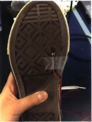
To determine the total potential strain energy that could be harvested from the bending of a shoe sole, simple strain tests were carried out on different points along the sole. A women's size 5 rubber-soled tennis shoe was used throughout all of the experiments. This particular shoe was chosen for it's relatively thin, flat, flexible sole. Axial strain gauges were used for all strain measurements and were attached using a cyanoacrylate adhesive. The two gauges were positioned so that their axes were aligned from the heel to the toe of the shoe.
Figure 2-1: Strain gauge attached to the sole of the shoe under the ball of the foot
As seen in Figure 2-1, The first strain gauge was placed beneath the ball of the foot, where the shoe bends most while the wearer is walking or running and where the most strain energy is expected to be stored and released. The second was placed on the sole halfway between the ball of the foot and the arch of the foot. The wires connected to each of the strain gauges were also secured to the sole and to the body of the shoe to prevent unwanted movement and resulting noise in the signal. All tests
were carried out on a flat, indoor surface.
Each strain gauge was individually wired to a wheatstone bridge circuit which was calibrated specifically to each of the strain gauges to compensate for any slight manufacturing variations. The wheatstone bridge was then fed into an amplifier, and
the resulting output voltage signal was read and analyzed.
The placement of these strain gauges enabled the general mapping of strain energy across the sole of the shoe. This allowed for a better understanding of where to place the energy harvesters to optimize the energy output for the specifications of the particular harvesters used.
Each of the strain gauges at the different locations along the shoe sole was subject to three different tests: walking, running in place, and rocking back and forth from heel to toe. Multiple actions were tested to produce a spectrum of energy data to understand the different motions that the piezoelectric energy harvesters would be able to handle at each location along the sole.
2.3.2
Testing Piezoelectric Energy Harvesters
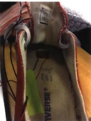
A smart-materials Macro fiber composite (MFC) d33 effect actuator/sensor1 was used
throughout testing as a piezoelectric energy harvester. To eliminate some inconsis-tencies, the harvester was first flexed by hand to break it in before testing began. The physical difference between the two types of MFCs is explained by Figure B-1 in the appendices of this thesis.
To avoid damaging the PZT fibers, the piezoelectric energy harvesters were at-tached to the inside of the shoe sole as opposed the exterior sole where the shoe makes direct contact with the ground. The harvesters were wired into a closed loop in series with a resistor. Various resistors were used over the course of the trials to compare outputs. The voltage drop across this resistor was measured and used in conjunction with the resistance value of the resistor used to calculate the energy collected and
'Important specifications for this particular device and a visualization of the difference between
d31 and d33 actuators/sensors can be found in Table A.4 and Figure B-1 respectively in the
appen-dices of this thesis.
Figure 2-2: d33 type PZT energy harvester secured inside the shoe under the ball of the foot
power produced throughout the tested motions. As before, the following motions were tested with the piezoelectric energy harvesters in place: walking, running in place, and rocking back and forth from heel to toe.
2.4
Results and Discussion
As was expected, the sole of the shoe was subject to significantly more straining at the ball of the foot than at the midpoint between the arch of the foot and the ball of the foot. Although not entirely apparent in the relaxed walking motions, measuring the shoe sole strain during running and rocking motions made it clear that more strain energy was being stored towards the ball of the foot where the shoe typically bends most.
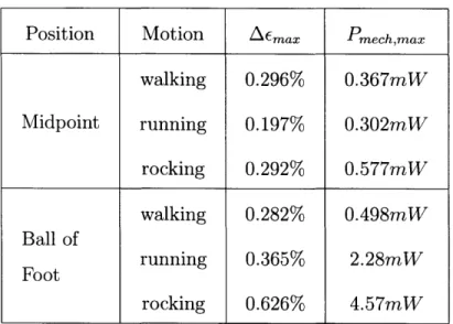
Due to the difference in the position of the strain gauges, numerical comparisons were made between the peak-to-peak amplitude of the strain AEma, in the shoe sole over the course of one step (or analytically speaking one cycle) as opposed to the
absolute strain c to account for the fact that the gauges experienced different resting strain once the shoe conformed to the wearer's foot.
Position Motion ' Emax Pmech,max
walking 0.296% 0.367mW Midpoint running 0.197% 0.302mW rocking 0.292% 0.577mW walking 0.282% 0.498mW Ball of Foot running 0.365% 2.28mW rocking 0.626% 4.57mW
Table 2.1: Measured Strain Testing Results
As seen in Figure 2-3, the walking motions produced strain amplitudes and profiles that were very comparable between the two points on the shoe sole. There was only a 0.014% strain difference between the respective Zemax values at the midpoint and
at the ball of the foot. This indicates that the strain was relatively constant in the middle area of the shoe while the subject was walking. However, as the activity became more rigorous, this difference increased. As seen in Figure 2-4 and Figure 2-5 and as quantified in Table 2.1, the difference in peak-to-peak strain amplitude between the two points on the shoe increased significantly to 0.168% strain and 0.334% strain as the subject carried out running and rocking motions respectively. While the ball of the foot experienced a change of 0.344% strain in peak-to-peak strain amplitude between walking and rocking motions, the midpoint did not experience such large amounts of fluctuation. The change in peak-to-peak strain amplitude between the same motions at the midpoint was a minuscule -0.004%.
From this data we can determine that, as predicted, the ball of the foot of the shoe houses significantly more strain potential energy over the course of various active motions than does the midpoint between the ball of the shoe and arch. Analyzing the corresponding strain power produced throughout the various motions further indicates
0.6 0.5 0.4 0.3 0.2 (I) 0.1 0 -0.1 -0.2' 0 1 2 3 4 5 6 Time [s]
Figure 2-3: Shoe strain while walking
that this location also has a higher potential energy harvesting power output.
Position Motion Pout,max/Area Pzt,max
walking 94.6 P 370.8 [uW Midpoint running 78.0 m 305.76 pW rocking 148.8 'W 583.3 [LW walking 128.5 P 503.7 puW Ball of running 587.8 t' 2.30 mW Foot CM2 rocking 1178.6 P 4.62 mW
Table 2.2: Power predictions for PZT energy harvesters
Converting the strain energy versus time data for each of the trials yields the strain power output at each of the two points of interest for the three different motions. The maximum strain power output Pmech,max listed in Table 2.1 at the midpoint between
the ball of the foot and the arch was rather consistent across all three motions.
25
Ball of Foot
--- -Midpoint
-
0.6 0.5 - 0.4- 0.3-E 0.12-0 1'3 0.1 %%.,~.,*I 1, 1, -0.2 0 1 2 3 4 5 6 7 8 9 10 Time [s]
Figure 2-4: Shoe strain while running
Using these values, Equations 2.7 and 2.8 were used in combination with the area of the strain gauge to determine the maximum power output per unit area that would be extracted by the PZT energy harvester at this point on the shoe. Documented above in Table 2.2, this maximum harvestable power per area Pout,max/cm2ranged from about 80O to 150w. Subsequently, using the active area of the MFC energy harvester used in this study, it was predicted that the maximum power output for
the harvesters Pzt,max would range from about 300pLW to 600pW.
The maximum strain power output Pmech,max of the three different motions at
the ball of the foot had a much larger range as predicted by the increasing strain in the shoe at that location as the activity became more rigorous. Unlike the Pmech,max
values at the midpoint, the maximum strain power output spanned almost a full order of magnitude at the ball of the foot throughout the three different motions. These
Pmech,max values correspond with maximum harvestable power per unit area values
Pout,max/cm2 ranging from about 130" to 1200'W and maximum power output
Ppzt,max ranging from about 0.5mW to 5mW, a significantly larger range and higher output than the harvestable power output at the midpoint. Comparisons between
26
Ball of Foot
- - -- Mid nint
0.6 0.5 - 0.4-0.3 0.2 --02 0 lI' 10. Ii -012 1I I 0 1 2 3 4 5 6 7 8 9 10 Time [s]
Figure 2-5: Shoe strain while rocking back and forth
the two cases can be seen in Figures 2-6, 2-7 and 2-8.
At 12001, a shoe sole surface area of 83.3cm2 would be required to reach the goal power output of 0.1W. Considering that this high power to area ratio. only occurs at a very small region of the shoe underneath the ball of the foot, it is unreasonable to predict that 0.1W is an achievable power output for these energy harvesters.
If the system were able to extract the maximum power from this study 4.62mW
constantly, it would take 216.5 hours or roughly 9 days to charge a single AAA battery. This would be a somewhat acceptable time frame which could be decreased by using multiple energy harvesters or harvesters with larger surface areas; however, this power value is the absolute peak power that was measured during this study, not the average power. This means that, assuming the user is walking, running, or rocking at some rate close to 1-2Hz, this power output would only be achieved for an instant every half to full second. In order to achieve an average power even close to this value to harvest any significant amount of energy in a reasonable amount of time, the user would need to be straining the sole of his or her shoe many orders of a magnitude more frequently than humanly possible. Though the operating frequencies of piezoelectric
Ball of Foot Miinint
0 0~ x 5 4 3 2 0 -1 -2 -3 -4 0 10 1 2 3 Time [s] 4 5 6
Figure 2-6: Strain power output while walking
energy harvesters are dropping as new developments arise (as exemplified by Ruize Xu's work
[20]),
much progress still needs to be made before piezoelectric harvesters can efficiently harvest energy from extremely low frequency walking and running motions.Although the data from the strain testing did not prove to be very promising for the effective use of piezoelectric energy harvesters in shoes, MFC actuators were still briefly tested on the shoes to confirm the low outputs.
28
- Ball of Foot
---- Midpoint
0-w-U) 0 0~ 5 4 3 2 1 0 -1 -2 -3 A 0 0-3 :10 Ball of Foot --- -Midpoint -1 2 3 4 5 Time [s] 6 7 8 9 10
Figure 2-7: Strain power output while running
Position Motion Pmeas,max
walking 62.8 nW Midpoint running 477.5 nW rocking 58.5 nW walking 172.1 nW Ball of Foot running 1.146 pW rocking 85.2 nW
Table 2.3: Measured power output from PZT energy harvester
The comparison of the MFC maximum power output values Pmeas,max in Table 2.3
with the maximum power output values Put,max predicted in Table 2.2 shows clear evidence that the energy harvesters are actually much less efficient than the strain testing had predicted. This makes sense because the predictions were calculated as absolute maximum possible peak power with the most optimistic efficiency
assump-x 10 5 Ball of Foot 4- ---- Midpoint 3 2-1 00A -2- -3--4 0 1 2 3 4 5 6 7 8 9 10 Time [s]
Figure 2-8: Strain power output while rocking back and forth
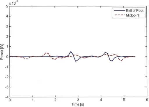
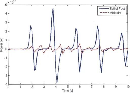
tions; however, these efficiency assumptions do not explain why the actual power output values are roughly three degrees of magnitude smaller than predicted. Most of the power output values predicted through strain testing trials are on the the order of 10' or 10' Watts while the actual values are on the order of 10' or 10-6 Watts. It is also peculiar that in both cases, when the MFC actuator was placed at the ball of the foot and when it was placed at the midpoint between the ball of the foot and the arch, the power output was significantly larger during the running motion that during either of the other two motions. This data is visualized in Figures 2-9 and 2-10. The strain data predicted that maximum power output would be detected during the rocking motion as opposed to the running motion; however, the data collected from the MFC actuator itself indicated that the rocking motion was the least powerful of the three.
These unexpected discrepancies between the predicted and measured values of the maximum MFC power output can be potentially attributed to multiple factors:
1. Surface placement of the original strain gauges 30
0.35 walking running 0.3- rocking 0.25 -00.2 -C3) 0.15-0L 0.1 -0.05 -- - -1-0 0 0.5 1 1.5 2 2.5 3 3.5 4 4.5 5 Time[s]
Figure 2-9: Measured power output from PZT energy harvester at the midpoint
2. MFC alignment and position
3. Coupling between the MFC actuator and the shoe
4. Strain gradient in the shoe sole
Due to the fact that the strain gauges used to test the strain energy and power in the shoe sole were adhered to the surface of the sole as opposed to being inset into the material, it is possible that the original strain measurements might have been affected by the direct contact force on the gauges. If this were the case, the strain and strain power output measurements would be higher than they should be.
To preserve the integrity of the actuators, the MFCs were not placed on the bottom sole of the shoe as the strain gauges were during the strain testing studies. Instead, they were attached to the interior sole of the shoe underneath the foot. This interior sole was made from a material different from the exterior sole, and the difference in the material's elastic properties likely had an impact on the power output. The fact that the MFC was closer to the foot than the strain gauges also likely contributes to
0.9 0.8 - running rocking 0.7 - 0.6-20.5- 1if 0.4 - if .I ipi I hII 03 .. 2. 4I foIt
III !iiJ~
III_
0.1- It riI ~
0 - osJ~~ 2. It
foott
the discrepancy in the order of magnitude.
The MFC actuator was secured to the inner sole of the shoe with tape instead of the epoxy typically used to adhere these actuators to surfaces. This choice was made to preserve the shoe; however, the tape did not secure the actuator at all points along the surface area as the epoxy would do. This likely allowed the MFC to somewhat separate from the sole surface while being strained, resulting in a low power output reading.
The strain gauges used to predict the maximum power output had a significantly smaller active area than the MFC actuators (see Tables A.3 and A.4 in the appen-dices of this thesis for specifications). The predicted maximum power output values
Ppzt,max listed in Table 2.2 were calculated based on the assumption that the expected power output per unit area PoUn ,max
/Area
was constant across the region of interest.Realistically, this Pout,max/Area is a function of location on the shoe sole, so the
ma-jority
of the area covered by the MFC actuator likely had a lower power output per32
unit area than the value calculated during strain testing.
Error aside, the MFC actuators were not efficient enough to perform up to the standards necessary to achieve the desired power output for this design study.
Chapter 3
Exploring New Methods of
Harvesting Energy
In order to use piezoelectric energy harvesters to charge any sort of battery in a reasonable amount of time, the devices would need to be several orders of magnitude more efficient than they are currently. For the scope of this project, it was decided that piezoelectric energy harvesters would not be the best choice of device to employ in shoes for harvesting energy from running and walking motions.
The idea of using a miniature electromagnetic generator within the shoe to convert kinetic mechanical energy into electrical energy was proposed, and the initial design consisted of a ratchet mechanism which would convert the transverse impact of the shoe's heel striking the ground into rotational motion of a rotor which would drive the electromagnetic generator. The core components of this mechanism were inspired by the idea of backdriving something like an optical disk drive motor, pictured in Figure
3-1, with a miniature version of the mechanism found is most salad spinners,
pic-tured in Figure 3-2. If some mechanism were robust enough to withstand the impact of the heel strike, then this concept could be considered plausible; however, before considering sturdiness and product reliability, both comfort and design integration were brought forth as concerns with this design.
Most shoes, especially shoes designed for performance and activity, have spring-like soles for comfort. They allow the users to sink into their steps to keep from
Figure 3-1: Optical disk drive motor Figure 3-2: Salad spinner that converts
[19] translational to rotational motion [18]
subjecting the their feet and subsequently their joints to large and often detrimental impulses. Similar to airbags, but on a much less extreme scale, shoe soles lengthen the time of impact of the foot on a surface to decrease the rate at which the person's momentum changes with each footfall. This cushioning shoe sole property provides comfort.
The ratchet mechanism derived from the salad spinner would not be easily altered to fit this sort of model to provide comfort to the user; however, the air pockets that shoe companies already incorporate into their designs already suffice to dampen the foot fall. Considering this method of dissipating energy which has already been proven to provide ample comfort to the user, the design of the proposed energy harvester evolved and the ratchet to electromagnetic generator coupling was replaced by a coupling between a miniature air turbine and an electromagnetic generator. A proof of concept model was developed with the purpose of estimating an order of magnitude of the potential power output of the system when subjected to walking and running motions.
Similar to the calculations used in Chapter 2 to determine the amount of power collected but the piezoelectric energy harvester, power was calculated using the mea-sured voltage output of the back-driven motor Vmea, and then know internal resistance of the motor Ri:
P Vmeas - I Vmeas Ri V 2 P =me"a Ri (3.1) (3.2) (3.3)
3.1
Apparatus and Procedure
Parts three
for the prototype were sourced from common pre-existing mechanisms. The main sourced items were:
1. Miniature Motor
2. Pressure-Driven Dental Drill
3. Blood Pressure Cuff
Figure 3-3: Miniature motor used as a generator in this study [8]
The miniature motor, pictured in Figure 3-3, was selected for its size and potential to be easily integrated into a small attachment for the shoe. Motors of this scale are commonly coupled with off-balanced masses to produce vibrations in devices such as cell phones. This small-scale motor was chosen to be back driven as a generator for the system.
Figure 3-4: Standard dental handpiece [16]
Figure 3-5: Various turbine designs used in modern pressure-driven dental drills [1]
The dental drill, pictured in Figure 3-4, is a tool widely used by dentists to drill holes in teeth for cavity removal and other procedures. The tool is capable of gener-ating large amounts of torque for this purpose and consists of a miniature air turbine that is driven by compressed air of pressures between 30-40psi and rotates at no-load frequencies up to 400,000rpm. The device works by taking in high pressure air through valves entering the base of the handle, forcing that air through a turbine at the head of the device where the air turns a rotor and attached dental drill bit, and then passing the air back through a valve at the base of the handle. A schematic of the mechanism itself within the housing can be found in the appendices of this thesis in Figure B-2.
The turbine within the drill was the part of interest for this study as it has already been optimized for widely used medical equipment. This means that energy losses to friction in the piece have already been minimized, and the parameters of the rotor itself have been optimized to provide significant amounts of torque. Evident in Figure
3-5, various geometries of rotors can be found within the dental handpiece market 38
Figure 3-6: Dental drill air turbine [2]
Figure 3-7: Blood pressure pump bulb [3]
and are used to operate at different pressures and output various ranges of torques, but for cost purposes we used a very simple handpiece turbine pictured in Figure 3-6. Finally the blood pressure cuff was acquired solely for the use of the hand pump bulb, pictured in Figure 3-7 and the tubing. Once again, this is a product that has already been iterated and optimized for medical devices. The rubber bulb is easy enough to compress by hand, and adjustment of the flow valve at the base of the bulb allows for the application of a maximum of about 30psi via hand pumping. There is a potential to increase this pressure value when considering that the air bulb will be subject to the impact of a footfall as opposed to a hand squeeze. The bulb is also equipped with an air inlet which allows air to refill the pocket once the bulb has been released. This inlet closes when an outside force is applied to the bulb to maintain pressure and to force air through the valve and connected tubing.
To assemble these three core components, the dental drill was first disassembled. The connector piece that typically joins the handpiece to the compressed air source
was removed and the drill's flow valves were exposed. The tubing from the blood pressure cuff was then attached to the drill's air intake valve and the other end of the tubing was attached to the pump bulb. The air outlet valve of the dental drill was left untouched so air flowing out of the turbine could flow back out into the environment. The back of the head of the drill was then removed, exposing one end of turbine within. The spindle of the miniature motor was inserted into the hole running through the axis of the turbine's rotor. For the sake of preserving the part for future configurations and iterations, the initial tests were run with out permanently
adhering any of the components.
With the components in place, the pump bulb was subjected to footfalls ranging from a typical walking step to jumping up and down. The flow valve at the base of the pump bulb was set to be as closed as possible to allow for maximum pressure
output.
3.2
Results and Discussion
From initial testing, this setup generated power outputs on the order of 10-4 to
10-Watts. Although formal tests have not been carried out, these ballpark measurements are enough to predict significantly higher power outputs than those generated by the MFC actuators. The use of the electromagnetic generator not only allows for the direct conversion of the kinetic energy of the footfall to potential energy, but it has the potential to generate a much higher average power output as the inertia of the rotor inside of the generator will keep the rotor spinning for a period of time in between steps. This slower response is much more ideal for the low frequency inputs of walking and running motions while the MFC actuators are more ideal for very high frequency inputs.
Knowing that this setup is a plausible method for obtaining reasonable electrical power outputs for harvesting and storing energy, there are several improvements that should be imposed upon the system to maximize these power outputs:
1. Improve Couplings
2. Decrease the length of tubing
3. Optimize pressure bulb
Neither of the couplings between the motor and turbine and the turbine and the tubing were ideal for minimizing energy losses in the apparatus. The motor was not rigidly adhered to the turbine as it was very difficult to align the central axes of the two components. The flexibility in the coupling was necessary to keep the system from jamming and preventing the generator from operating properly. In future iterations, the turbine and generator rotors should be combined into a single piece to ensure
alignment and to prevent energy losses to friction in an extra coupling.
This apparatus would also benefit from the limiting of the distance across which the air must travel between the pump and the turbine. Energy loss in fluid flow is a function of this length, so attaching the pump closer to the turbine will increase the power output-of the system while also shrinking the device itself.
The pressure bulb, as is, has been optimized for hand pumping; however, footfalls apply much more force to the pump than hand squeezing. Experimenting with the size, material, flow valve size and air inlet size would benefit the apparatus. Optimiz-ing these parameters would produce a higher air pressure out of the flow valve and into the air turbine, ultimately generating a higher power output.
42
Chapter 4
Conclusion
After carrying out strain testing on the sole of a shoe, it was determined that, even in the most optimal situation imaginable, one in which the energy harvester is perfectly coupled to the outer sole of the shoe at the point of maximum straining under the ball of the foot, an MFC actuator might be able to harness a peak output power on the order of 10-Watts. When actually tested, the MFCs yielded a maximum peak output power three orders of magnitude smaller than that. Combined with that fact that these actuators would need to be sensing this peak power at very high frequencies as opposed to the 1Hz - 5Hz of walking or running, it can be concluded
that piezoelectric energy harvesters are not the ideal choice for harnessing energy to charge batteries on the go.
The newly proposed device, which involved an air pocket pump coupled to a miniature air turbine and subsequently coupled to a miniature electromagnetic gen-erator, produced much more promising results. This apparatus built from sourced parts for testing purposes yielded peak power outputs on the order of 10-3W, the absolute maximum power that was expected from the piezoelectric energy harvesters in the most ideal conditions, in a non-optimal, proof-of-concept state. It was also much more well suited for low frequency inputs closer to the walking or running fre-quencies as the inertia of the turbine and coupled generator rotor induced a much slower response.
eliminated and replaced by custom pieces to allow for the optimization of parameters. The generator rotor and the turbine should be combined into one piece to ensure a sound coupling between the two elements, and the tubing attached between the pump and the turbine inlet valve should be shorted and coupled in a more permanent way to minimize energy losses. These alterations, combined with the optimization of the pump for foot falls and heel strikes should increase the device efficiency and hopefully increase the power output by at least one order of magnitude.
Appendix A
Tables
Power Output Weight Walking Pace Method of Estimation
5 W 52kg 2 steps see 40-ply triangular PVDF plate
with a center metal shim de-flected 5cm [17]
8.4 W 68kg 2 steps sec Mechanical spring and a rotary
generator conversion, with 67W available power
[17]
14 W 70kg 1 step sec 130% of the weight exerted with
1cm heel displacement [15]
16.4 W 70kg 1 step sec Based on the heel and toe force
and maximum 1cm allowable dis-placement [4]
67 W 68kg 2 steps sec Assume the fall of the heel
through 5cm [17]
324 W 68kg 2 steps see Power consumed during walking
[13]
Power Output Device Description
300-650mW Cylindrical PZT stack with hyr-daulic amplifiers [4]
20mW peak power 2mm flexible plastic substrate 1mW average power sandwiched in the middle of 16
layers of PVDF sheets [10]
80mW peak power Unimorph strip of spring steel 2mW average power bonded to piezoceramic material
[10]
1W peak power AC electromagnetic generator 0.25mW average power with lever and flywheel [10]
800mW Electroactive polymers or dielec-tric elastomers membrane
[9]
1.4mW peak power Triboelectric nano-generator [7] 27.5mW peak power Piezoelectric bimorphs coupled
with amplification mechanism [6] Table A.2: Outputs of pre-existing walking energy harvesters [21]
Table A.3: Strain Gauge Specifications [12]
46
Manufacturer Micro-Measurements
Model CEA-06-240UZ-120
Resistance 120Q t 0.3%
Gage Factor Q 24 degrees C 2.140 +0.5%
Active Length 7.25mm
Active Width 3.82mm
Table A.4: MFC Specifications [11]
Manufacturer Smart Material
Model M 2814 P1 (d33)
Active Length 28mm
Active Width 14mm
Appendix B
Figures
MFC P1 Type (d33effect) Elongator " powerful actuator * sensitive sensor
MFC P2 Type (d3 1effect) Contractor
* Low Impedance sensor
" energy generator
metal layer -IDE metal layer -IDE metal layer -surface
I
I
- PZT - epoxy
- PZT
+ + +
Figure B-1: Comparison of d33 and d31 MFC actuators [11] epoxy
U.S. Patent
May 11, 1976 Sheet I of 23,955,284
,-~-- -, 228 Je / 12 111/01/ 12 . ?"G4.--jo ,Z G 6. 36 J8 I -.50 --36 16 /542 52 57 H4 54/G. 7
.
Figure B-2: Schematic of the dental handpiece
[5]
50
Bibliography
[1] American Dental Accesories. http://www.amerdental.com/blog/tech-tips-22/.
[2] American Dental Accessories. http://www.amerdental.com/turbines-handpieces-and-dental-parts/turbines?limit=all.
[3] AllHeart. http://www.allheart.com/prestige-medical-replacement-bulb-and-valve-combo/p/pm80bva/.
[4] J[ames] F. Antaki, G[ina] E. Bertocci, E[lizabeth] C. Green, A[hmed] Nadeem, T[homas] Rintoul, R[obert] L. Kormos, and B[artley] P. Griffith. A gait-powered autologous battery charging system for artificial organs. ASAIO Journal, 1995.
[5] J.E. Balson. Disposable dental drill assembly, May 11 1976. US Patent 3,955,284. [6] M[ingjing] Cai and L[onghan] Xie. Increased piezoelectric energy harvest-ing from human footstep motion by usharvest-ing an amplitication mechanism.
Center for Nutrition Policy and Promotion, 2014.
[7] J[un] Chen, L[ih-Juann] Chen, T[e-Chien] Hou, Z[hong Lin] Wang, Y[a] Yang,
and H[ulin] Zhang. Triboelectric nanogenerator built inside shoe insole for har-vesting walking energy. Elsevier Journal, 2013.
[8] Ebay.
http://www.ebay.com/itm/load-3-7v-85ma-39500rpm-coreless-motor-size-7mm-dia-16-5mm-l-lmm-shaft-dia-/190881446150.
[9] V[iktoria] Greanya, C[ynthia] Daniell, and C[olleen] Nehl. Energy harvesting
technology development at darpa. Materials Research Society Journal, 2011.
[10] J[ohn] Kymissis, C[lyde] Kendall, J[oseph] Paradiso, and
N[eil] Gershenfeld. Parasitic power harvesting in shoes.
Second IEEE International Conference on Wearable Computing Journal,
1998.
[11] Smart Material. http://www.smart-material.com/media/datasheet/.
[12] Micro-Measurements. http://www.vishaypg.com/micro-measurements/stress-analysis-strain-gages/all-linear-patterns/.
[13] D[udley] J. Morton. Human locomotion and body form, a study of gravity and
[14] United States Department of Agriculture. Estimated calorie needs per day by age, gender, and physical activity level. Applied Physics Letters Journal, 2014.
[15] J[oseph] A. Paradiso and T[had] Starner. Energy scavenging for mobile and
wireless electronics. Pervasive Computing IEEE Journal, 2005.
[16] Dental Office Products. https://www.dentalofficeproducts.com/dental-handpieces.
[17] T[had] Starner. Human-powered wearable computing. IBM Systems Journal, 1996.
[18] Target. http://www.target.com/p/mini-salad-spinner/-/a-516266. [19] TT-Store. http://www.tt-store.com/images//ps2/.
[20]
Nuize
Xu. The design of low-frequency, low-g piezoelectric micro energy har-vesters. Master's thesis, Massachusetts Institute of Technology, 2012.[21] R[uize] Xu, S[ang-Gook] Kim, and K[elsey] Seto. Human body mountable energy harvesters. SUTD-MIT International Design Center, 2014.
52