Development of Modular Real-Time Software for the
TALARIS Lunar Hopper Testbed
by
Christopher J. Han
B.S. Aeronautics and Astronautics
Massachusetts Institute of Technology, 2009
Submitted to the Department of Aeronautics and Astronautics
in Partial Fulfillment of the Requirements for the Degree of
Master of Science in Aeronautics and Astronautics
at the
MASSACHUSETTS INSTITUTE OF TECHNOLOGY
June 2011
0 2011 Massachusetts Institute of Technology.
All rights reserved.
ASAC T TUTE
S ROS
ARCHIVEs
Signature of Author: ... ... . C...
Department of Aeronautics and Astronautics
May 6, 2011
Certified by: ...
....
... ... ... ...
David W. Miller
Professor of Aeronautics and Astronautics
Thesis Supervisor
C ertified b y : ...
... ...
. ... ...
Mic1 el C. Johnson
Senior Member of the Technical Staff, Draper Laboratory
Thesis Supervisor
A ccep ted b y :
...
---Eytan H. Modiano
Associate Professorf Aeronautics and Astronautics
Chair, Graduate Program Committee
Development of Modular Real-Time Software for the
TALARIS Lunar Hopper Testbed
by
Christopher J. Han
Submitted to the Department of Aeronautics and Astronautics
on May 19, 2011 in Partial Fulfillment of the Requirements for the Degree of Master of Science in Aeronautics and Astronautics
Abstract
Hoppers have recently emerged as a viable means for planetary exploration, and as with any new vehicle, significant testing is required to validate guidance, navigation, and control
(GNC) algorithms. Furthermore, the structure, organization, and timing of the real-time
software must be planned before software development begins in order to design an architecture which can match the needs and requirements of the vehicle as they evolve throughout its lifecycle. These issues are compounded in an academic environment, where software knowledge is not necessarily present and must be obtained and practiced before it can be applied. In addition, high student turnover rates can result in difficulty retaining institutional knowledge of the working software and causes further development delays while new students are trained. These problems were addressed by the TALARIS software team by implementing a flexible, modular software solution in LabVIEW on the National Instruments Real-Time Input/Output (RIO) board. After a brief introduction to the TALARIS testbed, the theory of flexibility and modularity is described as applied to the TALARIS software. In particular, the unique FPGA + PowerPC architecture and its importance to precise, real-time
GNC execution are explored. Various software modules are isolated and analyzed, and
several test cases are presented to illustrate the benefits of modular software with regard to development time, testing procedure, and debugging. Examples from software development, actuator characterization, and test campaigns illustrate the gradual evolution of the prototype software. Finally, a discussion of the conclusions from the work and future work is presented. Thesis Supervisor: David W. Miller
Title: Professor of Aeronautics and Astronautics Thesis Supervisor: Michael C. Johnson
Acknowledgements
First and foremost, I would like to sincerely thank the MIT Space Systems Laboratory and Draper Laboratory for funding my graduate work and making this thesis possible. The Draper Laboratory Fellow program has allowed me to start on an exciting new project, work amongst a great team, and experience the real world of space systems
engineering. Thanks to my advisors Dr. David W. Miller and Michael C. Johnson, whose guidance and support for the past two years have been crucial to my growth as a graduate student. I would also like to recognize Lesley Yu and National Instruments for their gracious donation of hardware and software and unwavering support of the project.
Additionally, I would like to thank the TALARIS team for all their hard work. There are too many people to list them all, but I would like to recognize a few key individuals at the risk of leaving someone out. Dr. Hoffman has been a great PI and leader on the project, and it has been an honor to work under such a prestigious figure in the space community. Bobby Cohanim and Phillip Cunio have been absolutely the best systems engineers I have worked with in my six years at MIT. Their gentle but firm leadership has been the foundation of the TALARIS team, and they always had a knack for pushing just the right amount for maximum results. Special thanks go to Chris Wardman for many of the underlying themes and ideas that drove the development of the time software. Chris taught me about FPGAs, real-time programming, and pushed me to always stay one step ahead of the hardware team. Without his ideas and insight, this thesis would not have been possible.
Among the TALARIS students, Claas Olthoff stands out as a superman, tirelessly working 18hr days and consistently taking the last T home. His work ethic was an inspiration, and I learned much from his original software scheme even after he had left. Thanks to my only 2011 classmate on the TALARIS team, Sarah Nothnagel, for going through the pains of grad school together and providing the occasional comic relief. I will always remember the late-night pset sessions that we had. Special thanks go to my software grasshopper, Chris Rossi, for graciously accepting the LabVIEW torch and easing my workload. I hope your LabVIEW skills prosper and surpass my own. Good luck to the next DLF generation: Chris, Joe, and Ted! For anyone else on the team I have not mentioned, my sincerest thanks for all the hard work and good times. Your contributions have not gone unnoticed.
Last but not least, I would like to thank my friends and family for supporting me throughout my time at MIT. I might have gone crazy had it not been for your welcome distractions. Thanks Mom and Dad for all your love and support throughout the years, for always encouraging me to chase my dreams, and for pushing me to realize my full potential. Your teachings since I was a child, along with God's blessings, have made me into the person
I am today and have allowed me to succeed in life. I dedicate this thesis to you and offer my
Assignment
Draper Laboratory Report Number T-1682
In consideration of the research opportunity and permission to prepare this thesis by and at The Charles Stark Draper Laboratory, Inc., the author hereby assigns copyright of the thesis to The Charles Stark Draper Laboratory, Inc., Cambridge, Massachusetts and the
Massachusetts Institute of Technology. The author hereby grants to MIT and Draper
Laboratory permission to reproduce and distribute publicly paper and electronic copies of this thesis document in whole or in part.
Contents
1
IN TR O D U CTIO N ... 171.1 M OTIVATION AND APPROACH ... 18
1.2 LITERATURE REVIEW ... 19
1.2.1 Flexibility Theory...19
1.2
.2 M o d u la rity ... 2 1 1.2.3 FPGAs in Real-Time Software... 221.3 THESIS OVERVIEW ... 23
2 BA CK G R O UND ... 25
2.1 GOOGLE LUNAR X PRIZE...25
2.2 INTRODUCTION TO TA LAR IS... 26
2.3 TA LAR IS SYSTEM S OVERVIEW ... 29
2 .3 .1 S tru ctu res ... 2 9 2.3.2 Electric Ducted Fans (EDFs) ... 30
2.3.3 Cold Gas System ... 31
2.3.4 Lithium Polymer Batteries ... 33
2 .3 .5 A ltim eter ... 3 3 2.3.6 Gladiator IM U...34
2.3.7 National Instruments sbRIO-9642 Board ... 35
3 FLEXIBILITY AND M O D ULA RITY ... 37
3.2 M ODULARITY ... 38
3.3 M ODULARITY IN LABV IEW ... 40
3.3.1 Creating sub-vi's...41
3.3.2 Mapping functional and physical structure ... 43
3.3.3 Using sequences to organize code ... 45
3.3.4 Call C Library Function Node ... 46
4 REAL-TIME SOFTWARE ARCHITECTURE... 47
4.1 A VIONICS HARDW ARE O VERVIEW ... 47
4.2 GN C SPECIFICATIONS ... 50
4.3 GN C TIM ING ... 54
4.4 FPGA SOFTW ARE ... 59
4 .4 .1 T im er L o op ... 62 4.4.2 Altimeter Transmit ... 62 4.4.3 Altimeter Receive...65 4.4.4 IM U Receive ... 67 4.4.5 Sensor Acquisition ... 69 4 .4 .6 C G S L o op ... 70
4.4.7 Load Cell Receive...73
4 .4 .8 E D F L o op ... 74 4.5 PPC SOFTW ARE ... 76 4.5.1 M ain PPC.vi ... 77 4.5.2 FPGA Interface.vi...80 4.5.3 GNC Exec.vi ... 81 4.6 G SC SOFTW ARE ... 82
5 APPLYING MODULARITY TO TALARIS SOFTWARE...85
5.1 M ODULARITY IN D EVELOPMENT... 86
5.1.1 FPGA Development ... 86
5.1.2 PPC Development...88
5.1.3 GNC Timing...90
5.2 M ODULARITY IN O PERATION ... 92
5.2.1 Single EDF Testing ... 93
5.2.2 M ulti-EDF RPM Testing...94
5.2.3 M ulti-EDF JDOF Altitude Testing ... 96
5.2.4 CGS Single Stream...9...97
5.2.5 CGS Characterization and Load Cell Testing ... 98
5.2.6 CGS Testing
IDOF
Traverse...1005.2.7 GNC Testing 3DOF Traverse ... 101
5.2.8 GNC Testing JDOF Attitude...103
5.2.9 GNC Testing 2DOF Attitude + Altitude ... 105
5.3 SOFTW ARE M AINTENANCE U SING M ODULARITY ... 107
5.3.1 Flexibility of the RS-232 interface ... 107
5.3.2 Upgrading IM Us...109
5.3.3 Upgrading RPM sensor ... 110
5.3.4 Integration of new sensors ...
111
6 D ISCU SSIO N AND CO N CLUSION S...113
6.1 THESIS REVIEW ... 113
6.2 FUTURE W ORK ... 114
REFEREN CES ... 117
APPENDIX A: SOFTWARE OPERATIONS GUIDE ... 121
A .1 QUICKSTART GUIDE... 121
A .2 LOADING SOFTW ARE ... 122
A .3 RUNNING TESTS... 125
A.3.1 Starting Software...125
A.3.2 Running Scripts ... 128
A. 3.3 Resetting Software ... 130
A .4 U PLOADING DATA TO THE SVN ... 131
A .5 TROUBLESHOOTING ... 134
A.5.1 Software Troubleshooting ... 134
A.5.2 SVN Troubleshooting ... 135
A .5 .3 O th er N o tes ... 13 8
List of Figures and Tables
FIGURE 1: SOLIDW ORKs DRAWING OF TALARIS TESTBED v2 ... ... ... 27
FIGURE 2: TALARIS (LEFT) AND GLXP (RIGHT) HOP PROFILES ... 28
FIGURE 3: TALARIS V2 CARBON FIBER BODY (UNDERSIDE) [21] .. ... 29
FIGURE 4: TA LA RIS AXiS CONVENTIONS... 30
FIGURE 5: EXPLODED VIEW OF AERO-NAUT TF8000 EDF WITH CUSTOM INLET AND FAIRING [20] ... 31
FIGURE 6: FRONT AND BACK VIEWS OF THE ASSEMBLED EDF [20] ... ... 31
FIGURE 7: OMEGA SV128 SOLENOID VALVE [24] ... ... 32
FIGURE 8: VALVE ORIENTATION AND NUMBERING CONVENTION ... ... ... 33
FIGURE 9: AR1000 LASER DISTANCE SENSOR [25] .. ... ... 34
FIGURE 10: GLADIATOR LANDMARK 30 1MU [26] .. ... ... ... 35
FIGURE 11: NATIONAL INSTRUMENTS SBRIO-9642 [27] ... ... ... 36
FIGURE 12: CAPTURING COMPLEXITY WITH A SUB-VI ... ... 42
FIGURE 13: MAPPING FUNCTIONAL AND PHYSICAL STRUCTURE (TEXT-BASED CODE) ... 43
FIGURE 14: MAPPING FUNCTIONAL AND PHYSICAL STRUCTURE (LABVI EW)... 44
FIGURE 15: O VERVIEW OF FLIGHT SHELL.Vi ... 45
FIGURE 16: LABVIEW CALL C LIBRARY FUNCTION NODE... ... ... 46
FIGURE 17: AVIONICS HARDW ARE ARCHITECTURE... 48
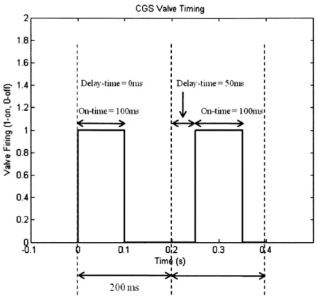
FIGURE 18: C G S V ALVE TIM ING ... 51
FIGURE 19: VALVE OFF-PULSING FOR +Z M OMENT ... 52
FIGURE 20: G N C U PDATE TIM ING DIAGRAM ... 53
FIGURE 21: SOFTWARE GNC EXECUTION BLOCK DIAGRAM ... ... ... 55
FIGURE 22: G N C EXECUTIO N TiM ELINE... 56
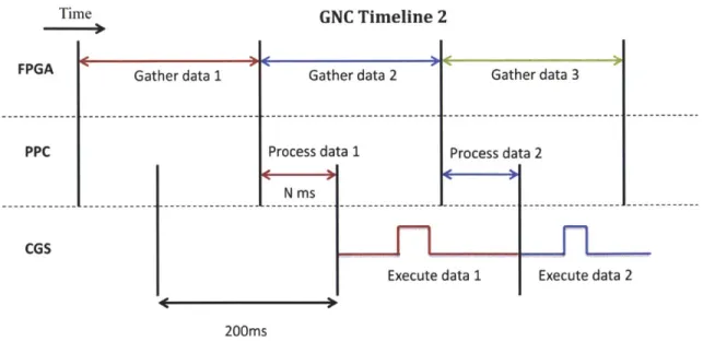
FIGURE 23: G N C EXECUTION TIM ELINE 2 ... 57
TABLE 1: GNC TIMING BENCHMARK RESULTS ... 58
FIGURE 25: LABVIEW BLOCK DIAGRAM FOR FPGA MAIN.VI ... 61
FIGURE 26: LABVIEW BLOCK DIAGRAM FOR FPGA TIMER LOOP... ... 62
FIGURE 27: ALTIMETER TRANSMIT ... 62
FIGURE 28: ALTIMETER COMMAND EXAMPLE... 64
FIGURE 29: ALTIMETER RECEEIVE ... 65
FIGURE 30: RS-232 FALLING EDGE DETECTION ... 66
FIGURE 31: M U RECEIVE... 67
TABLE 2: GLADIATOR IM U DATA PACKET [26] ... 68
FIGURE 32: SENSOR ACQUISITION ... 69
FIGURE 34: CGS M ANUAL FIRE LOOP... 70
FIGURE 35: CGS DUTY CYCLE FIRE LooP ... 71
FIGURE 36: CGS FRAME OFFSET AND M VARIABLES ... ... ... ... 72
FIGURE 33: LOAD CELL RECEIVE ... 73
FIGURE 37: EDF INITIALIZATION ... 74
FIGURE 38: ED F M ODULE ... 75
FIGURE 39: M AIN PPC.vi FRONT PANEL ... 77
FIGURE 40: M AIN PPC.VI BLOCK DIAGRAM ... 78
FIGURE 41: FPGA INTERFACE.VI BLOCK DIAGRAM ... 80
FIGURE 42: GNC EXEC.VI BLOCK DIAGRAM ... 81
FIGURE 43: FLIGHT SHELL.VI BLOCK DIAGRAM ... 82
FIGURE 44: N2 DIAGRAM OF FPGA MODULE INTERACTIONS... 87
FIGURE 45: OVERVIEW OF M AIN PPC.V ... 89
FIGURE 46: PPC SUB-VI EXECUTION TREE ... 90
FIGURE 47: FRAME-LOCKED VS. FRAME OFFSET EXECUTION ... 91
FIGURE 48: CGS FRAME OFFSET CODE ... 92
FIGURE 49: SINGLE E DF TEST SETUP ... 94
FIGURE 50: CLOSED-LOOP RPM RESPONSE ... 95
FIGURE 51: M ULTI-EDF ALTITUDE TEST STAND ... 96
FIGURE 52: CGS SINGLE STREAM TEST STAND... 97
FIGURE 53: CGS STATI C TEST STAND ... 98
FIGURE 54: CGS VALVE FIRING PROFILE ... 99
FIGURE 56: G N C 1DO F TRAVERSE STAND ... 101
FIGURE 57: GNC 3DO F TRAVERSE TEST STAND .. ... ... ... 102
FIGURE 58: iDO F ATTITUDE TEST STAND ... 103
FIGURE 59: EULER ANGLES FOR BALANCED ATTITUDE TEST... ... ... 104
FIGURE 60: EULER ANGLES FOR TW O UNBALANCED TESTS... 105
FIGURE 61: 2DO F ALTITUDE + ATTITUDE TEST STAND ... ... ... 106
FIGURE 62: A LTIM ETER SEND M ODULE ... 108
FIGURE 63: CROSSBOW MU SEND MODULES... ... 108
Acronyms
Al
- Analog InputAO - Analog Output
CGS - Cold Gas System
DI - Digital Input
DIO - Digital Input/Output
DMA - Direct Memory Access
DO - Digital Output DOF - Degree of Freedom
EDF - Electric Ducted Fans
FIFO - First In First Out
FPGA - Field Programmable Gate Array
GLXP - Google Lunar X PRIZE
GNC - Guidance, Navigation, and Control
GSC - Ground Station Computer
IMU - Inertial Measurement Unit
LLRV - Lunar Landing Research Vehicle LLTV - Lunar Landing Training Vehicle LSB - Least Significant Bit
NGL - Next Giant Leap
PPC - Power PC
PWM - Pulse Width Modulation RIO - Real-Time Input/Output
TALARIS
-
Terrestrial Artificial Lunar And Reduced gravIty Simulator
Chapter 1
1 Introduction
Over the past two decades, rovers have been the primary vehicle architecture for mobile ground-based planetary exploration. With the success of Sojourner in 1996 and the Mars Exploration Rovers (MER) in 2003, NASA has gained valuable flight experience and reliability with the rover architecture and plans to launch its largest rover yet, the Mars Science Laboratory (MSL) in 2011. However, ground-based rovers depend on automatic path-planning algorithms which are computationally expensive and require long calculation times on radiation-hardened processors. For example, a typical 15m traverse for the MER rovers took an average of three minutes of processing time from image acquisition to position update, which limited the overall speed of the rover to approximately 10 m/hr [1]. The calculation time coupled with the communication lag and rough terrain severely limited the speed and range in which the rovers could operate. In 555 sols (1 sol = 1 Martian day = 1.02 Earth days), Opportunity traveled just 5974m [2]. These limitations of rovers have motivated a desire to use a hopper architecture for mid-to-long range traversals, which is potentially capable of traversing kilometers in a matter of minutes, instead of months or years. A planetary hopper uses impulsive jets to launch itself into either a ballistic trajectory or a fixed-attitude, rectangular flight profile and land softly in the desired location. By flying over rough terrain, hoppers may visit scientifically interesting locations otherwise unavailable to rovers, such as the interior of craters or valleys. Hoppers that use a fixed-attitude flight profile can also perform science during the traverse, for example while scaling
a cliff to observe geologic features. In addition, a hopping system could be added to an existing lander platform to augment the accuracy of its entry, descent, and landing (EDL) system and potentially lower overall cost. Insertion from orbit could be performed with a larger error ellipse than conventional EDL systems, using a small hop to fine-tune the final landing site. Such planetary hoppers have already begun to garner interest for the
deployment of a seismic sensor network, which requires sensors to be separated by long distances and would otherwise be costly and time-consuming for a rover to deploy [3].
Despite all their benefits, hoppers have little to no flight history and require
significant prototyping and testing to demonstrate flight maturity. TALARIS, or Terrestrial Artificial Lunar And Reduced gravIty Simulator, was designed to be an Earth-based testbed to prototype hopper technologies and test guidance, navigation, and control (GNC)
algorithms. Using TALARIS, hopper GNC algorithms may be validated in a relevant environment on Earth for a fraction of the cost of a space-qualified vehicle. The Next Giant Leaps team intends to use the results from TALARIS to develop its entry for the Google Lunar X-Prize, a $30 million competition to travel to the moon, traverse a set distance, and send back data, pictures, and video.
1.1 Motivation and Approach
The main value of TALARIS as a testbed is its ability to quickly adapt to a series of different contexts and testing configurations. Rapid changes in vehicle configuration are expected, and the architecture must be flexible enough to accommodate a variety of GNC algorithms, flight profiles, acceleration and deceleration commands, gravity offsets, and test stands. In order to achieve these goals, the need arose for a software architecture that is flexible, easy to learn, and which facilitates a short development cycle. Modularity was applied to the real-time software, allowing different components of the software to be developed in parallel. Also, these modules were designed to be easily switched out
depending on the vehicle configuration, allowing a customized suite of sensors and functions for each test campaign.
In addition to making the software flexible, the reliable, real-time execution of GNC algorithms can be a challenging task. There is an inherent tradeoff between achieving faster control cycles, and thus the possibility of finer control of the vehicle, and computation time, communication delay, and actuator delay. Furthermore, most GNC algorithms rely on precise timing information to determine the vehicle state and issue commands, but also require complex calculations within a short control cycle. These problems were addressed through the use of a field programmable gate array (FPGA) in conjunction with a PowerPC processor to achieve both the timing needs and the calculation requirements for the hopper
GNC algorithms.
The objective of this thesis will be two-fold. First, it will detail the architecture of the real-time software necessary for the robust and reliable execution of GNC algorithms,
resistant to jitter, communication delays, and other runtime irregularities. Second, it will document the use of modularity in the development, operation, and maintenance of the software and provide examples from each of the three phases to demonstrate the benefits of modularity.
1.2 Literature Review
1.2.1 Flexibility Theory
Flexibility theory studies the ability of a system to respond to a change in the
environment of a system while minimizing the costs of such changes. Much of the literature on flexibility is currently focused on large scale, capital-intensive projects, such as energy or transportation infrastructure, where high investments make it essential to use flexibility in systems design. Lin, et al. [4] noted four characteristics which make such systems difficult to design: long lifetime, uncertain market conditions and performance, multidisciplinary scope which could lead to emergent behaviors, and significant economic and societal impact. Decisions about system architecture must be made at an early stage and under highly uncertain environments, and high capital investment accentuates the risk. As an example,
Iridium and Globalstar pioneered space-based telephony in the late 1990s, investing millions in a satellite communications network. However, neither company accounted for the rise of ground-based cellular technology in the mid 1990s, which lowered demand for space-based communication networks. The deterministic market predictions by Iridium and Globalstar as well as the inability to downsize and reconfigure its network for a different purpose resulted in losses of $5 billion and $3.5 billion respectively [5]. Instead, de Weck, et al. [5] suggest using a staged deployment, starting with a smaller, more affordable network and adding capacity by launching additional satellites and reconfiguring the constellation in orbit. In such large-scale projects, flexibility is driven by the need to adapt to future uncertainty and improves lifecycle value by mitigating downside risks.
Smaller academics projects, such as TALARIS, also benefit from employing flexibility to mitigate uncertainty. However, while large-scale projects tend to focus on changing stakeholder interest and market dynamics, uncertainty in smaller projects usually stems from changes during the development process such as shifting requirements definitions and budget and schedule constraints. Furthermore, academic projects often suffer from high personnel turnover rates as student schedules shift, and keeping institutional knowledge of the system can be a challenging task. This can be mitigated by maintaining rigorous documentation, but fluctuations in student availability stills adds additional uncertainty to future development potential.
The TALARIS theory of flexibility, first described by Cunio [6] and applied by Olthoff [7], attempts to make flexibility theory applicable to small, advanced vehicle development. Cunio describes several methods to impart flexibility to a system, each
designed to either maximize the system's ability to change or minimize the costs to the system, whether they be monetary, schedule, personnel time, or complexity. These methods will be discussed in further detail in Chapter 3.
1.2.2 Modularity
Modularity has been applied for years in engineering. In 1995, Ulrich wrote a seminal paper exploring the connection between modularity in product architecture and manufacturing firm performance [8]. Ulrich defined modular and integral architectures as the following:
"A modular architecture includes a one-to-one mapping from functional
elements in the function structure to the physical components of the product, and specifies de-coupled interfaces between components. An integral architecture includes a complex (non one-to-one) mapping from functional elements to physical components and/or coupled interfaces between components" [8].
Ulrich explored the advantages of each architecture in several areas of "managerial" importance, such as product change, product variety, component standardization, product performance, and product development management.
More recently, both Gaillard [9] and Holtta [10] explored the impact of applying modularity to the automotive assembly line. Gaillard urged automotive manufacturers to
adopt open standards on the assembly line and to reduce complexity through modularization. Holtta explored the tradeoff between different levels of modularity and noted that modularity may often come at a cost that engineers are not willing to pay. For example, light weighting, tight packaging, and lower power consumption may drive engineers towards more integral,
less flexible architectures [10].
Software modularity is not a new idea, but the consistent application of modularity can sometimes be a challenging process. Cai and Huynh [11] stated that both aspect-oriented and object-oriented programming techniques were intended to allow one part of the software to change independently of the rest of the system. In addition, a modularization technique benefits a design only if future changes to the design can be accommodated by the technique.
Thus, the application of a specific technique should be evaluated against potential future changes [11]. Tan [12] described a method which uses the Larch/C Interface Language (LCL) to encourage modular style programming by developing a formal framework with specified
re-engineering process which improved modularity and robustness without changing the base functionality or performance [12].
1.2.3 FPGAs in Real-Time Software
In the past two decades, FPGAs have emerged as a viable means to program flexible real-time software for small robotics. In 1995, Corba and Ninkov [13] implemented a 2D real-time image centroiding algorithm on an FPGA, noting the high parallelism,
pipelineability, and modularity of the FPGA architecture. Several distinct filter
configurations were pre-compiled and stored on the FPGA allowing for quick swapping after deployment. These characteristics also make the FPGA attractive for implementing GNC algorithms on experimental small robotics, where the creation of customized embedded systems can be costly and time consuming. Falsig and Soerenson [14] described a modular architecture for low level control called TosNet, which implemented modular controllers over a standard network in the FPGA to control up to 15 nodes. KrishnaKumar, Kaneshige, et al.
[15] used a FPGA in a similar way, describing a "plug and play" avionics system called
iPapa. The goal for iPapa was to allow new hardware to be plugged into the system and automatically configured without the need for a manual setup procedure [15]. Again, this type of architecture was valuable by avoiding the need to design individual avionics solutions for different vehicles or configurations.
All of these examples stress the reconfigurability and parallelability of the FPGA to
design modular interfaces on a standard framework. However, the implementation of more complicated GNC algorithms in a FPGA remains difficult and takes up an enormous amount of resources in the FPGA. For example, an accurate divide operation consumes an immense amount of resources in an FPGA compared to a traditional processor, and much research has been done to develop an efficient division algorithm using the FPGA's fixed-point logic [16]. In addition, VHDL, the standard programming language used in FPGAs, is difficult to learn and understand for inexperienced coders. In an academic environment, this translates to valuable development and operation time spent on training new personnel. This thesis presents a new software architecture which combines a FPGA and a traditional PowerPC
processor to take advantage of their respective strengths while minimizing their weaknesses. In particular, the parallelism and reconfigurability provided by the FPGA will be used to develop modular sensor and actuator interfaces, and the processing power from the PowerPC will be used to execute GNC algorithms. The software will be written in the LabVIEW environment, which is both easy to learn and understand, and the benefits of modularity will be demonstrated in different phases of the vehicle development.
1.3 Thesis Overview
This thesis is divided into six chapters. Chapter 2 provides background information regarding the Google Lunar X-Prize as well as a system overview of the TALARIS testbed. Chapter 3 introduces the theory of flexibility and modularity as they have been applied to the vehicle software and forms the theoretical foundation for the thesis. Chapter 4 begins with a
description of the TALARIS avionics hardware and a discussion of GNC algorithm execution and timing, and finishes with an overview of the real-time software architecture as
implemented in LabVIEW. In particular, the unique FPGA + PowerPC architecture and its importance to GNC execution will be explored in great detail. Chapter 5 focuses on the application of the modularity principle to the TALARIS software architecture. Various modules will be isolated and analyzed, and several test cases will be presented to illustrate the benefits of the modular software with regard to development time, testing procedure, and debugging. Examples from software development, actuator characterization, and test campaigns will illustrate the gradual evolution from prototype to flight software. Finally, Chapter 6 will conclude the thesis with a summary and recommendations for future work.
Chapter 2
2 Background
2.1 Google Lunar X PRIZE
The Google Lunar X PRIZE (GLXP) is an international competition organized by the X Prize Foundation and sponsored by Google to motivate privately funded teams to land on the moon, traverse at least 500m, and send back high definition images, video, and data. The first team to do so before the end of 2015 will receive a $20 million grand prize, while the second team will get a $5 million second place prize. In addition, a number of bonus prizes worth up to $4 million will be awarded for various extra goals, such as traveling ten times the baseline requirement (5000m), verifying water ice on the moon's surface, surviving the lunar night, and precision landing near the Apollo landing sites or other sites of interest [17].
To compete in the Google Lunar X Prize, the Next Giant Leap (NGL) team was founded in 2007 by Michael Joyce. Its technical partners include the Sierra Nevada Corporation, Draper Laboratory, Aurora Flight Sciences, and the MIT Space Systems Laboratory. Unlike other teams competing for the GLXP, the Next Giant Leap team has decided to use hopping technology, rather than the more conventional lander with a rover, to achieve the GLXP requirements. Hoppers, which are not limited by rough terrain, have the potential to traverse longer distances than rovers, but have no flight heritage and thus are considered as a higher risk. The Next Giant Leap team is also interested in developing
hopper technology in the long term to "provide transportation and support for a variety of science and commercial payloads to low gravity bodies such as our moon, the asteroids, and Phobos" [18]. However, as an untested technology, prototype hoppers must first be
developed and tested, and Draper Laboratory, as a member of the NGL team, has been tasked to develop the guidance, navigation, and control (GNC) algorithms for the NGL vehicle. To test these algorithms in a relevant environment, the TALARIS prototype testbed was
developed at Draper Laboratory in conjunction with the MIT Space Systems Laboratory.
2.2
Introduction to TALARIS
TALARIS was originally conceived in Spring 2008 by the 16.89 Space Systems Engineering graduate design course and represents an MIT/Draper collaboration to develop a terrestrial testbed for testing hopper GNC algorithms. Using terrestrial testbeds such as TALARIS, GNC algorithms may be tested for relatively low cost in a simulated environment on Earth before deployment. Similar to the Apollo program's Lunar Landing Research Vehicle (LLRV) and its successor the Lunar Landing Training Vehicle (LLTV), TALARIS uses a dual propulsion system: one as the primary impulsive propulsion and a second to provide gravity offset and simulate lunar conditions. In the case of the LLRV and LLTV, a gimbaled turbofan jet engine was used to provide weight relief, and hydrogen peroxide rockets were used to simulate the thrusters on the Lunar Module [19]. On TALARIS, four electric ducted fans (EDF) are used to relieve 5/6 of the vehicle's weight, leaving the rest of the vehicle to experience 1/6 th of the Earth's gravity, as it would on the Moon. The vehicle
uses nitrogen cold gas thrusters as the primary propulsion system to provide impulsive thrust.
Figure 1: SolidWorks Drawing of TALARIS Testbed v2
In addition to simulating a lunar environment, the TALARIS platform was designed to simulate other astronomical bodies, including Mars, Phobos, and asteroids, as long as they have gravity lower than Earth. Furthermore, each of the propulsion systems can be switched out for more powerful upgrades, such as gas-turbine engines to replace the EDFs or hydrogen peroxide/hydrazine thrusters for the cold gas system (CGS). The avionics hardware was designed to be flexible as well, to accommodate these configuration changes [7]. This thesis will concentrate mainly on the development of real-time software to take advantage of the hardware flexibility, allowing streamlined testing on a variety of platforms and test campaigns.
By using the nitrogen cold gas thrusters with gravity offset from the EDFs,
TALARIS will perform a level horizontal hover hop of 30m. In a trade-off study, 30m was chosen as a representative 1 g demonstration of a lunar hover hop [20]. The distance traversed is much lower than the GLXP requirement of 500m because of higher gravity, air resistance, and the lower specific impulse of nitrogen gas thrusters compared with hydrazine thrusters. The hop will be performed in three phases. First, the vehicle will operate the EDFs in steady-state to provide 5/6g offset. The four vertical gas jets will provide the necessary thrust to ascend to 2m and obtain stable hover, while the four horizontal gas jets will provide
roll control about the vertical. In phase 2, the vehicle uses horizontal jets to perform straight and level flight, providing the aggregate thrust to accelerate and decelerate laterally while off-pulsing to maintain heading (roll). The vertical jets will provide the required aggregate thrust to maintain altitude and will off-pulse to maintain pitch and yaw attitude. In phase 3, the vertical jets will slowly throttle down to perform a controlled descent and touchdown [21].
A conceptual drawing of the hop profile can be seen below in Figure 2.
Velocity up to 10-15 mis Velocity up to 15-20 m/s
. Compressed I 2m I Hydrazine
i
2m Gas + Fans mTBR IFigure 2: TALARIS (left) and GLXP (right) hop profiles
This hop profile is intended to recreate a lunar hop by providing similar forces and torques on the vehicle, as well as allowing the GNC algorithms to perform a hover hop in a controlled environment. It is important to note that the TALARIS vehicle is not the same as the final NGL vehicle and was never intended to be flight hardware or sent to the moon. TALARIS was meant for operation on Earth using analogues to the final vehicle to prove
2.3 TALARIS Systems Overview
2.3.1 Structures
The TALARIS v2 structure is composed of a single flat sheet of carbon fiber
composite with additional ribbing on the underside for added strength and cutouts to reduce mass. Custom machined EDF mounts are located on the four corners, canted at 150 for controllability. The structure measures 99cm long by 76cm wide by 8.9cm tall (frame only).
A picture of the underside of the carbon fiber body can be seen below [21].
Figure 3: TALARIS v2 carbon fiber body (underside) [21]
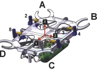
The axis conventions on the vehicle are consistent with the Draper GNC axis conventions, which are derived from the original Apollo coordinate system. In this
coordinate frame, +X is directly up from the vehicle, +Z is in the direction of the horizontal thrusters, and +Y completes the right-handed coordinate system. "Roll" will be referred to as rotation about the X axis, "Yaw" will be rotation about the Z axis, and "Pitch" will be
rotation about the Y axis. These axes will be referenced in later sections and are reproduced below with respect to the body orientation.
Figure 4: TALARIS Axis Conventions
2.3.2 Electric Ducted Fans (EDFs)
The TALARIS test bed uses four Aero-Naut TF8000 electric ducted fans to provide the 5/6 gravity offset. The EDFs are powered using Lehner 3060 fan motors and controlled with Schultz 40.160 motor controllers. The motors have a max rated power of 8kW, with max thrust at 6.37kW of power [20]. With an operating voltage of 45-50V from the lithium polymer batteries, the max current draw of the EDFs is 150A. In addition to the motor casing,
custom inlets and fairings were designed to reduce turbulence and increase efficiency. These were fabricated using stereolytographic (SLA) 3D rapid prototyping printing. With the inlet
and the fairing, each EDF produces about lOON of thrust at max thrust [20]. An exploded view as well as a completely assembled EDF can be seen in the figures below.
Motor
Fairing
Mounting Ring
Figure 5: Exploded view of Aero-Naut TF8000 EDF with custom inlet and fairing [20]
Figure 6: Front and Back views of the assembled EDF 1201
2.3.3 Cold Gas System
The TALARIS Cold Gas System (CGS) provides the final 1/6g thrust required for
takeoff as well as attitude, altitude, and horizontal control. The liftoff requirement is to traverse 2m vertically in 2s, which requires 486.4N with a 45kg vehicle. The EDFs provide
367.9N while the CGS provides 118.5N of vertical thrust [22]. Eight Omega SV128
providing horizontal thrust. The valves have a rated opening and close time of 30-60ms, but through the use of a custom PCB, the open and close lag have been reduced so that the minimum overall pulse on-time or off-time is 40ms [23]. The valves will be controlled at 5Hz. Pulse-width modulation (PWM) with pulsewidths between 40 and 160ms will be used to control vehicle translation, roll during traverse, pitch, and yaw. The same range of pulsewidths will be used along with a phase plane controller to control roll during vertical rise, hover, and vertical descent; however, in this case a 200ms pulsewidth will be allowed in order to make continuous firing over consecutive Control cycles possible. The Luxfer L65G flight tanks will be filled to 4500psi, providing a flight time of 44 thruster-seconds (e.g. 4 thrusters for 11 seconds). During vertical firings on a load cell, the valves provided an average of 58N per thruster, but this value can be affected by a variety of factors including runtime, tank pressure, temperature, and multiple valve firings [22]. An Omega SV128 can be seen below, as well as a figure showing the valve orientation and numbering on the vehicle. The vertical thrusters (VTs, corresponding to valves 1, 3, 5, and 7) nominally create upward thrust, while the horizontal thrusters (HTs, corresponding to valves 2, 4, 6, and 8) nominally create lateral thrust (2 and 8 provide +z thrust, 4 and 6 provide -z thrust).
A
2B
Figure 8: Valve orientation and numbering convention
2.3.4 Lithium Polymer Batteries
To power the EDFs, the vehicle uses ten Tanic 7S-lP 4500mAh lithium polymer
battery packs which are capable of discharging continuously at 135A. Two battery packs are wired in series to provide a nominal voltage of 51.8V, and five sets are wired in parallel to share the current draw. At full throttle, the high power system is capable of delivering 25kW to the EDFs [20]. During testing sessions, runtime is generally limited to below 45s at full throttle to prevent overheating of the batteries and motor controllers.
2.3.5 Altimeter
An Acuity AR1000 laser altimeter will be used to sense altitude and provide an update of the vertical degree of freedom. The AR1000 has a range from 0.1m to 30m with an accuracy of 3mm. It is being operated with a 10Hz update rate and communicates using the standard RS-232 communication protocol [25]. In the software, altimeter packets are being
treated as asynchronous because the altimeter does not use a sync signal to the RIO, so it does not send packets at exactly equal 1 Oms intervals.
Figure 9: AR1000 Laser Distance Sensor [251
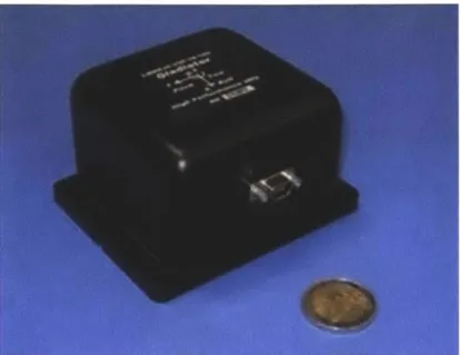
2.3.6 Gladiator IMU
The Gladiator LandMark 30 IMU was chosen to navigate the vehicle due to its high
performance, low noise and bias characteristics, and small size. The IMU uses RS485 to communicate data packets at a rate of 200Hz. These packets are synchronized to the RIO's clock using a 1kHz square wave, generated by the RIO's FPGA.
Most degrees of freedom will be determined by dead reckoning, so the flight will have to be kept short to prevent IMU noise from causing the state estimate to diverge. Alternatively, two additional upgrades to the navigation algorithm are planned to improve performance. The first will use four altimeters mounted at the corners of the vehicle to provide an attitude update, and the second will use a downward pointing camera to
implement vision navigation algorithms. Both updates are currently being prototyped and are not yet implemented on the vehicle.
Figure 10: Gladiator LandMark 30 IMU [261
2.3.7 National Instruments sbRIO-9642 Board
The National Instruments sbRIO-9642 (RIO) board handles all input/output functions on the vehicle and communicates telemetry data to the Ground Station Computer (GSC). This board was chosen for its low cost, small size and weight, high flexibility, and ease of development with real-time LabVIEW. At its heart is a 400MHz Freescale MPC 5200, a member of the PowerPC 5000 series of microprocessors. The processor runs the LabVIEW real-time module on the Wind River VxWorks real-time operating system and is connected to a 2M gate Xilinx Spartan-3 field programmable gate array (FPGA) through a high-speed PCI bus. The FPGA is connected to a number of digital and analog input/output choices,
including 110 3.3V bidirectional digital input/output (DIO) channels, 32 24V digital input (DI)/digital output (DO) channels, 32 ±1 OV analog input (Al) channels, and 4 ±1 OV analog output (AO) channels [27]. A custom aluminum case was built for the RIO with standard D-shell connectors attaching to the various input/output lines with ribbon cable. The RIO measures 8.2" x 5.6" and weighs 292g [27].
Figure 11: National Instruments sbRIO-9642 [27]
The RIO was chosen for its inherent flexibility, given the numerous input and output choices [7]. Of particular interest to this thesis is the ability to integrate c-code libraries into the LabVIEW code and run them as enclosed blocks. This feature allowed for the
modularization of the Draper GNC code so that development could be done for each of the separate GNC blocks. The separate algorithms could then be compiled together with an executive and enclosed in a single LabVIEW block.
Chapter 3
3 Flexibility and Modularity
3.1 TALARIS Theory of Flexibility
"Flexibility is a property of a system by virtue of which the system changes to gain maximum value in response to a change in the environment for the system" [6].
Flexibility is mainly a tool to deal with uncertainty. Small advanced vehicles are often affected by uncertainties in the development process, especially prototype vehicles, where changes in requirements and the project environment occur frequently and
unexpectedly. In these projects, flexibility can add downstream value in two ways: by maximizing the system's capability to change or minimizing the cost of a change, whether the cost be monetary, personnel time, or schedule. As noted by Olthoff [7], software is inherently flexible in the sense that any additional changes require no changes in hardware or monetary costs. However, personnel and schedule costs must also be taken into account when making a software change, and a flexible software architecture will make these changes
easy, quick, and seamless. Therefore flexibility in software will focus on minimizing the cost of a change, namely in terms of personnel time and schedule.
The TALARIS Theory of Flexibility as written by Cunio [6] states three techniques for imparting flexibility to small advanced vehicles. The first technique, maximum overhead
capacity, attempts to provide more of a specific resource than is minimally required,
essentially creating an overdesigned system. For example, the avionics system on TALARIS has more than twice the number of I/O pins necessary for the current sensor suite. The small amount of added mass from the extra pins must be weighed against the ability of the avionics system to incorporate a larger and more varied sensor suite in the future. The second
technique, creating a defined expansion path, attempts to predict possible future development paths to target system changes. By defining a discrete number of future possibilities, the
subsystems can be catered to adapt to the most probable choices or the widest possible subset of choices, thereby minimizing future cost and maximizing utility. The third technique, modularity, will be the focus of this thesis. In general, modules are designed to have
specified, de-coupled interfaces, making it easy to interchange modules to form different configurations. If a change in the system function is required, this change can be isolated to a few modules, leaving the rest of the system intact. In this way, the system is maximizing its ability to change (e.g. incorporating a new sensor suite) while also minimizing the time and complexity of this change. This technique is the easiest to apply to software, as there is no
"resource" to be maximized and future paths can be redesigned more efficiently with modular software. In this way, modularity can be thought of as an "enabler for flexibility"
[7].
3.2 Modularity
"A modular architecture includes a one-to-one mapping from functional
elements in the function structure to physical components of the product, and specifies de-coupled interfaces between components" [8].
Modularity provides a link between the physical structure and functionality of the code, increasing organization and reducing complexity. The code is separated into modules, which are defined from the rest of the system by de-coupled interfaces. Modules should have little to no dependence on other modules, allowing them to be switched, replaced, and
can be unavoidable. For example, the "Current Time" variable, which keeps a Ims timer, must be shared by all FPGA modules for accurate timestamping. In the case of such
interactions, the couplings must be well documented so that the module may still be replaced or removed without impacting the rest of the system.
When developing vehicle software with a large team, modularity can help maximize utility by breaking up the software into smaller tasks. Each module can be tested and validated individually, and several modules can be easily assembled into different configurations. When debugging, the problem can be isolated to a single or group of modules and debugged separately from the rest of the system. In this way, the development of the complete software can proceed in parallel, with different groups or individuals working on different modules. This scheme also decreases the complexity for students, since coders don't necessarily need to understand the entire software to code their individual module.
In the operations phase, the development of prototype software, i.e. software that encompasses only partial applicability or that has not been fully tested for flight reliability, helps to demonstrate functionality early and buy down risk. For example, it is common on TALARIS to separate the EDF and CGS propulsion systems for individual testing. Prototype software can be quickly assembled using only the appropriate modules for each system to allow for characterization tests to continue. By having prototype software ready and quickly customizable, hardware and software work streams can proceed in parallel without one
stream causing delays with the other. In addition, software functionality for each propulsion system can be validated individually, and the relevant modules can be later incorporated into the final version of the software.
Finally, modularity can also help in later phases of vehicle development. By increasing flexibility, modularity allows for the vehicle to undergo quick changes in
configuration and minimize setup times. For example, common modules such as the RS-232 interface can be repurposed or reused for similar functions. New compatible sensors can be easily integrated by using a standard communication protocol such as RS-232. In the long term, if the TALARIS testbed were to be upgraded to use more powerful propulsion systems, such as hydrazine rockets or gas-turbine engines, the core framework of the software can be left in place, with only the relevant modules being replaced.
* Increased organization
* Increased flexibility while not compromising base functionality * Separation of responsibility -makes debugging easier and facilitates
development with large teams
* Reduced complexity - makes code easier to understand and is useful for gaining experience in an academic environment
" Ability to easily switch out GNC algorithms speeds testing sessions
" Reusable -common modules can be easily modified for similar functions (i.e. RS-232 interface)
The detriments to modularity are a bit difficult to quantify. It is usually difficult to convert integral code to modular code a posteriori, which means a modular coding style must be adopted before development begins. During development, it is unclear whether integral or modular code requires longer development times. In some instances, the reduced complexity of modular code may aid programmers, but it may also create some redundancy which increases the runtime or amount of resources used. The tradeoff between performance and development time is central to the decision of using integral or modular code.
3.3 Modularity in LabVIEW
The LabVIEW programming language was chosen for the TALARIS project due to its ease of use and implementation for modular embedded systems. The intuitive graphical interface is easy to learn and understand for new students, which is crucial for passing on
software knowledge to the next generation. In addition, the graphical interface is inherently suited for modularity, as sections of code can be visually separated and further
compartmentalized through the use of sub-vi's. The graphical user interface (GUI) is
integrated into the creation of the code as a "front panel" which is paired with every vi block diagram. However, there are also some tradeoffs associated with LabVIEW. As a graphical programming language, all modules attempt to run as soon as inputs are available. Runtime execution is implied by the passing of information between modules (i.e. a module will not
run until all inputs are defined) or explicitly through the use of sequences. This makes multi-threaded programming relatively easy - by default, the code will run as many modules as possible in parallel. However, this makes serial programming more difficult. The order in
which modules execute is often crucial to proper performance, but this is not specified by LabVIEW unless explicitly controlled by the programmer. For many programmers used to programming in text-based languages such as C or Matlab, serial programming may be taken
for granted, and some amount of adjustment may be required to enforce runtime execution order. For the TALARIS project, LabVIEW acts as a higher level environment common to both the FPGA and the PowerPC (PPC) and represents a compromise between usability and complexity. For other projects, the traditional text-based methods for programming a FPGA and PPC, such as VHDL and C, might be more attractive choices.
There are four main features of LabVIEW which make it especially suitable for developing modular code. The first feature described below is the ability to create sub-vi's, since it is possibly the most useful in terms of modularity. The other three features, described in the other subsections below, are also helpful in this regard. The graphical nature of
LabVIEW makes clear the mapping between the functional and the physical structure of the code. The availability of sequences eases organization of the various modules into a cohesive body of code, and the Call C Library Function Node provides the capability of seamlessly calling pre-compiled C code as separate modules.
3.3.1 Creating sub-vi's
A sub-vi is a section of code which has been compartmentalized and is represented by
a single icon on the block diagram of the top-level vi. Sub-vi's are most commonly used to represent functions, where inputs and outputs are well defined, and may be copied to produce multiple instantiations as needed. Sub-vi's can also be used to capture more complex code, which is useful in making the top-level vi less complicated and more readable. Below is an example of a sub-vi which handles the GNC execution in the PPC.
Figure 12: Capturing complexity with a sub-vi
Sub-vi's hide complexity from the top-level vi, increasing readability in both vi's, while simultaneously modularizing the code. On the top level, the sub-vi can be thought of
as a black box with only inputs and outputs. When the code needs to be debugged, the bug can be narrowed to a certain sub-vi and modified separately from the main code. Sub-vi's also naturally specify module interfaces, as the inputs and outputs must be pre-determined to pass information into the sub-vi (the sub-vi and top-level vi have different variable scopes). Although a vi can often be thought of as a module, a module is not necessarily a single vi. There may be several modules inside a single vi, as is the case in the FPGA software, where all the sensor interfaces are contained within a single vi in separate modules.
3.3.2 Mapping functional and physical structure
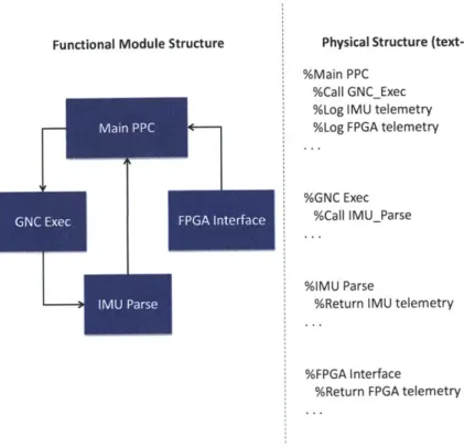
Due to the graphical nature of LabVIEW, a block of code can be immediately understood in terms of its relation to other blocks, and their interactions can be intuitively seen. In text-based code, even if the functions are well-separated, they are still written serially, and their execution order or tree is not immediately obvious. In the figures below, a simplified example has been taken from the PPC code. The functional block diagram is shown on the left while pseudo-code is shown on the right.
Functional Module Structure
I-U
Physical Structure (text-based) %MainPPC
%CalIGNCExec %Log IMU telemetry %Log FPGAtelemetry
%GNCExec %Call IMUParse
%IMU Parse
%Return IMU telemetry
%FPGA Interface
%Return FPGA telemetry
Figure 13: Mapping Functional and Physical Structure (text-based code)
Nlair PPC.
-Functional Module Structure Physical Structure (text-based) %Main PPC
%Call GNCExec %Log IMU telemetry %Log FPGA telemetry
%GNC Exec %Call IMUParse
%IMU Parse
%Return IMU telemetry
%FPGA Interface
%Return FPGA telemetry
Figure 14: Mapping Functional and Physical Structure (LabVIEW)
In this example, Main PPC acts as the main executable, calling GNC Exec and receiving data from IMU Parse and FPGA Interface. In the text-based example, the
programmer must keep the functional diagram in mind while coding text serially; even if the code is well-separated by function, their execution order is not immediately obvious. In LabVIEW, the programmer may make the actual code visually resemble the functional block diagram. Main PPC can be coded with an output which sends data to GNC Exec and two inputs which receive data from IMU Parse and FPGA Interface. The color of the line
indicates the data type (e.g. double, int32, etc.) of the inputs and outputs, supplying further information to the programmer. In this way, the physical structure in LabVIEW can be made to closely resemble the functional structure, which is one of the defining qualities of
modularity.
Main PPC
3.3.3 Using sequences to organize code
In LabVIEW, sequences are used to explicitly define runtime execution order. Sequences are composed of a series of frames which run in series and are arranged either horizontally, as in a flat sequence, or one behind the other, as in a stacked sequence. Frames also create natural boundaries which can be used to organize code and define modules. Information can flow into and out of a frame in much the same way inputs and outputs are defined in a sub-vi. All three of the above modularity techniques can be observed in the example below, taken from Flight Shell.vi.
Figure 15: Overview of Flight Shell.vi
Flight Shell.vi is composed of a single flat sequence of four frames that are intended to be run in order. This ensures that the variable initialization, which happens in the first frame, happens before the PPC is called, which happens in the second frame. Logging happens in the third frame, with each of five logging text files being created by their respective sub-vi's. In the final frame, all the text files are closed and the PPC execution is stopped. In this way, each frame is defined by a specific function and separated by
boundaries. Execution can be thought of as a block diagram: Initialization -> Start PPC -> Logging -> Stop PPC, with the physical structure matching its functional counterpart.
Sub-vi's are used to hide the complexity of the logging routines, which are functionally simple but take up a large amount of space. The goal of these techniques is to create code which is easy to follow and understand while also easy to debug and maintain. Future software developers, even with limited LabVIEW experience, can quickly review the entire code and understand the different modules.
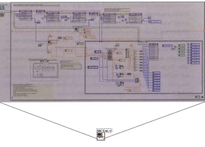
3.3.4 Call C Library Function Node
The fourth feature of LabVIEW that makes it useful for developing modular code is its Call C Library Function Node, which is shown below.
TGNC_exec_vO.out:TalarisGNCexec II In DEL DEL C3 C3 C3 C3 IR It I DBElL DBLT
Figure 16: LabVIEW Call C Library Function Node
This block allows pre-compiled C code to be run in LabVIEW as an enclosed module with pre-defined inputs and outputs. On the TALARIS vehicle, this block is used to run the Draper GNC code, which is coded in C, Matlab, and Simulink and auto-coded to C when necessary. A "TGNC exec_vO.out" file is compiled for the RIO in advance and may be
easily switched out to test different algorithms. For example, several versions of the GNC code with different control gains can be pre-compiled and switched during operation to make the best use of testing sessions, which require long setup times and several personnel on staff. Unfortunately, C encapsulation gives no insight into bugs and creates opaque crashes. Often a bug in the C code will either freeze the entire LabVIEW software or in the worst case, crash the RIO, requiring a reboot. However, insight into the GNC code can be provided by a judicious choice of variables to be output as telemetry, and the frequency of opaque crashes
Chapter 4
4 Real-Time Software Architecture
This chapter is intended to familiarize the reader with the design of the real-time software written in LabVIEW. The first three sections introduce the RIO hardware
architecture, the GNC algorithms, and the GNC timing. The flight software was developed to meet the specifications summarized in these sections. The second three sections will describe the three main components of the flight software: the FPGA, PPC, and GSC code. The LabVIEW code will be discussed in detail, and the focus will be on providing a
functional overview as well as a detailed documentation of the software. The information in this chapter will form the technical basis for the discussion of application of modularity to TALARIS in Chapter 5.
4.1 Avionics Hardware Overview
The software is divided between three computing entities: the FPGA, the PowerPC processor, and the GSC. This architecture is enabled by the use of the National Instruments RIO board, which includes both a FPGA and a PowerPC, as well as a number of analog and digital inputs and outputs. By implementing modular software, this architecture can become heavily customizable and quickly reconfigured, and the high number of I/O pins allows for many devices to be implemented at once. These capabilities aligned with the overall design
cues of TALARIS: ease of development, flexibility, and reliability. A diagram of the avionics hardware architecture can be seen below.
Oth RS-232
Actuators
Sensors
RIO
GSC
* Hardware
interfaces
-
Timing
-
Flight controls
-
GNC execution
-
Communication
Wireless Communication- I
I
I
I
*
Start Execution
GSC'
LoggingFigure 17: Avionics Hardware Architecture
The FPGA executes at the lowest level of the three computing entities and handles all sensor and actuator interfaces. It is also the most heavily modularized, as each sensor or actuator interface operates more or less independently, and can be separated, reorganized, or omitted depending on the vehicle configuration. All sensor and actuator telemetry is
generated here and is timestamped on the FPGA's 40MHz clock. The data is then passed to Altimeter

![Figure 3: TALARIS v2 carbon fiber body (underside) [21]](https://thumb-eu.123doks.com/thumbv2/123doknet/14733808.573675/29.918.244.662.454.774/figure-talaris-v-carbon-fiber-body-underside.webp)

![Figure 5: Exploded view of Aero-Naut TF8000 EDF with custom inlet and fairing [20]](https://thumb-eu.123doks.com/thumbv2/123doknet/14733808.573675/31.918.155.818.145.395/figure-exploded-view-aero-naut-custom-inlet-fairing.webp)