Image-guided failure assessment of human trabecular bone – Inverse finite
element modelling for characterization of elastic properties
Alexander Zwahlen1, David Christen1, Davide Ruffoni1, Philipp Schneider1, Werner Schmölz2, Ralph Müller1 1Institute for Biomechanics, ETH Zurich, Switzerland
2Universitätsklinik für Unfallchirurgie, Medizinische Universität Innsbruck, Austria
[email protected] Abstract: Local interpretation of micro finite element (µFE)
simulations has become important in different fields of bone biomechanics. Although on an apparent level µFE has suc-cessfully been validated against experiments, local valida-tions are sparse and limited by imaging resolution. At the tissue level heterogeneity of Young’s modulus has been re-ported. Although non-uniform material distribution have been shown to only have a minor influence on the apparent material properties, its impact on local material behaviour is largely unknown. By combining image-guided failure as-sessment (IGFA) using synchrotron-based-micro-computed tomography, strain mapping and inverse µFE modelling, we present an experimental and computational framework which will allow studying local effects of intratrabecular heterogeneity of the Young’s modulus.
Keywords: Image-guided failure assessment, strain
map-ping, synchrotron radiation µCT, inverse µFE modeling
Introduction
Local interpretation of micro finite element (µFE) analy-sis has become important in bone structure-function rela-tionships, stress concentrations around osteocyte lacunae, crack initiation and failure studies. µFE simulations based on micro-computed tomography (µCT) images have suc-cessfully been validated with experimental measures such as apparent stress and strain. Unfortunately local valida-tions of strains are sparse and the resulting low correla-tions with experiments were explained by limited image resolution affecting the experimental and simulated strains [1]. Experimental nano-indentation studies have reported intratrabecular heterogeneity of Youngs’s modu-lus. Including the variation in Young’s modulus based on measured mineral density only marginally influenced apparent level properties of µFE simulations [2]. Never-theless intratrabecular heterogeneity may further explain the low local accuracy of µFE simulations.
Improvement of the local accuracy of µFE could be achieved by investigating different local distributions of elastic moduli. Here, we propose to calculate an optimal modulus distribution that produces locally accurate µFE simulations. For this we performed image guided failure assessment (IGFA) [3] to measure experimental dis-placement fields and local strain maps using a deformable image registration algorithm [4]. Combining displacement and strain measurements with inverse µFE modelling [5]
will allow the investigation of the local heterogeneity of the Young’s modulus.
Methods
Materials and specimen preparation
Forty trabecular bone specimens (Ø 6 mm x 9 mm) were excised from fresh frozen thoracic vertebral (Th 9-12) bod-ies. The age of the 11 donors (5 females, 6 males) ranged from 27 to 83 years (median 76 years, mean 68.1 ± 16.7 years). Using a diamond core drill (Breu Diamantwerkzeug GmbH, Arbon, Switzerland) samples were drilled out in cranial-caudal direction and bone marrow was washed out subsequently. Using a precision saw (IsoMet 5000, Buehler, Lake Bluff, IL, USA) specimen ends were cut parallel to each other to ensure a precise length (9 mm). Prior to IGFA testing all 40 specimens were analyzed for bone volume density (BV/TV) and heterogeneity based on standard µCT imaging (µCT 40, Scanco Medical AG, Brüttisellen, Swit-zerland) at a nominal resolution of 12µm, a voltage of 70 kVp and a current of 114µA.
For the IFGA experiments 12 specimens spanning a range of BV/TV from 4.8% to 21.8% (mean 9.86% ± 4.84%) were selected. The chosen specimens originated from 8 human donors (4 females, 4 males) aged from 27 up to 82 years (median 74 years, mean 64.0 ± 17.8 years). Stainless steel end plates were glued on the specimens top and bottom end using commercially available cyanoacrylate glue. Apart from the gluing procedure the specimens were stored in phosphate buffered saline (PBS) or frozen in PBS-soaked gauze to ensure wet conditions during testing.
Image-guided failure assessment (IGFA)
Using a previously published micro-compression device [6], the IGFA experiments were performed as follows: First the specimens were loaded with a preload of 3N before an alter-nating sequence of micro-compression tests (uniaxial strain) and SRµCT imaging was repeated in steps of 0.5% strain until failure. Finally, the specimens were unloaded and im-aged again by SRµCT. The strain-rate was set to 0.01% per second and a relaxation time of 20 min was allowed before imaging in order to prevent movement artifacts. Mechanical strain was applied by a plunger with a spherical tip acting on the top endplate while the bottom endplate was fixed. SRµCT imaging was performed at the TOMCAT beam-line of the Swiss Light Source (Paul Scherer Institute, Villigen, Switzerland) using a beam energy of 17.5 keV and 1081 projections. The entire specimens were scanned at a nominal Biomed Tech 2013; 58 (Suppl. 1) © 2013 by Walter de Gruyter · Berlin · Boston. DOI 10.1515/bmt-2013-4114
image resolution of 7.4µm resulting in roughly 1200x1000x1000 voxels or 8.9x7.4x7.4 mm3.
Deformable image registration and strain mapping
From the IGFA experiments local displacements were calcu-lated with a demons deformable registration algorithm as described in [4]. Local strains were then derived from the displacement fields in three dimensions.
Inverse micro finite element (µFE) analysis
In order to estimate the distribution of the local Young’s modulus, the experimentally measured strain and displace-ment fields were combined with µFE. In Figure 1, a sche-matic of the inverse FE algorithm is shown. Starting with a homogenous modulus distribution a “simulated strain” was computed with µFE by imposing proper local boundary conditions (BC). The new modulus distribution was estimat-ed proportionally to the ratio between “simulatestimat-ed” and “ex-perimental” strain before starting the loop again.
Figure 1: Flow chart of the proposed inverse µFE analysis
Results
For 10 out of 12 specimens IGFA experiments were suc-cessful and they allowed strain mapping for each loading step. The number of loading steps varied between speci-mens and 68 loading steps were measured in total. Strain mapping was performed for the entire specimens allowing global as well as local failure patterns to be visualized and animated (Figure 2a,b). Displacements from the strain maps allowed the application of experimental boundary conditions for µFE calculations of a subset (Figure 2 c).
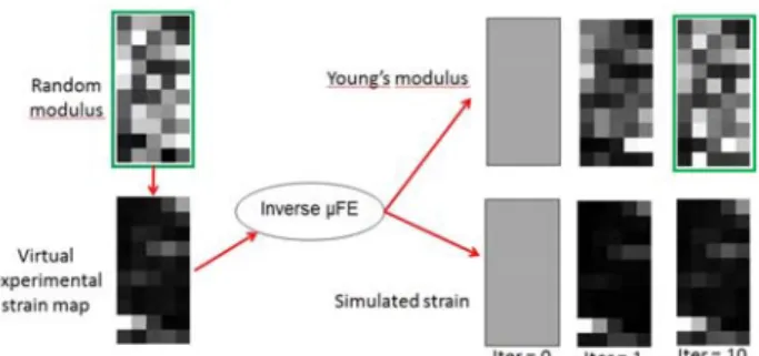
Figure 2: Strain map of a) specimen loaded at 3% appar-ent strain, b) of single trabeculae and c) µFE with experi-mental BC (note: different color scales for a, b and c) For verification of the inverse µFE algorithm a random Young’s modulus distribution in 2D was used to create a virtual experimental strain (Figure 3). For this virtual experimental strain, the inverse µFE algorithm was run for 10 iterations starting from an initial guess (iter=0) using a homogenous Young’s modulus providing updated distributions of Young’s modulus approaching the “real” distribution defined for the virtual case (Figure 3).
Figure 3: Inverse µFE applied to random modulus
Discussion
With 10 successfully measured samples we could show that IGFA using SRµCT was feasible for larger number of specimens, providing strain maps, visual inspection and quantitative analysis (Figure 2a and b). Furthermore, local strains were successfully derived and experimental boundary conditions imposed on µFE simulations based on IGFA experiments (Figure 2c). The µFE derived strain patterns using a homogenous Young’s modulus differed from the experimental strain (Figure 2c vs. 2b) supporting the need of a heterogeneous modulus distribution for locally accurate µFE simulations. The presented experi-mental and computational framework allowed the inverse µFE algorithm to be applied to experimental IGFA data. The test case for the inverse µFE successfully converged towards the virtual modulus distribution (Figure 3, green box). From this we conclude that a Young’s modulus distribution can be calculated that allows µFE simulations to be accurate. Currently, large scale inverse µFE simula-tions are running on all samples. From the resulting mod-ulus distributions relations between density and Young’s modulus as well as between location and modulus can be investigated. Incorporating such relations in µFE simula-tions will improve the local accuracy of µFE simulasimula-tions.
Acknowledgement
The authors would like to thank Marco Hitz for technical support. Alina Levchuk and Sandro Badilatti are acknowledged for their support during the experiments.
Bibliography
[1] R. Zauel, Y. N. Yeni, et al., J. Biomech. Eng., vol. 128, pp. 1-6, 2006.
[2] T. Gross, D. H. Pahr, et al., Comput. Methods
Biomech. Biomed. Engin., vol. 15, pp. 1137-1144,
2012.
[3] A. Nazarian and R. Müller, J. Biomech., vol. 37, pp. 55-65, Jan 2004.
[4] D. Christen, A. Levchuk, et al., J. Mech. Behav.
Biomed. Mater., vol. 8, pp. 184-193, Apr 2012.
[5] A. Maniatty, N. Zabaras, et al., Journal of
Engineering Mechanics-Asce, vol. 115, pp.
1303-1317, Jun 1989.
[6] P. Schneider, A. Levchuk, et al., Biomedizinische
Technik/Biomedical Engineering, vol. 55, pp. 8-10,