HAL Id: tel-03162841
https://tel.archives-ouvertes.fr/tel-03162841
Submitted on 8 Mar 2021
HAL is a multi-disciplinary open access
archive for the deposit and dissemination of sci-entific research documents, whether they are pub-lished or not. The documents may come from teaching and research institutions in France or abroad, or from public or private research centers.
L’archive ouverte pluridisciplinaire HAL, est destinée au dépôt et à la diffusion de documents scientifiques de niveau recherche, publiés ou non, émanant des établissements d’enseignement et de recherche français ou étrangers, des laboratoires publics ou privés.
Hongjian Wu
To cite this version:
Hongjian Wu. Process Modeling and Planning for Robotic Cold Spray Based Additive Manufacturing. Material chemistry. Université Bourgogne Franche-Comté, 2020. English. �NNT : 2020UBFCA026�. �tel-03162841�
THESE DE DOCTORAT DE L’ETABLISSEMENT UNIVERSITE BOURGOGNE FRANCHE-COMTE
PREPAREE A L’UNIVERSITE DE TECHNOLOGIE DE BELFORT-MONTBELIARD
Ecole doctorale n° 37
Sciences physiques pour l’ingénieur et microtechniques - SPIM Doctorat de Sciences pour l'Ingénieur
Par
Mr. Hongjian WU
Process Modeling and Planning for Robotic Cold Spray Based Additive Manufacturing
Thèse présentée et soutenue à UTBM Site de Sévenans, le 15 Décembre 2020
Composition du Jury :
Mr.Pasquale Daniele CAVALIERE Professeur, Université de Salento Rapporteur Mr. J Paulo Da Silva BARTOLO Professeur, Université de Manchester Rapporteur
Mr. Kondo Hloindo ADJALLAH Professeur, Université de Lorraine Examinateur (président) Mr. Hanlin LIAO Professeur, UTBM Examinateur
Mr. Sihao DENG Maître de Conférences-HDR, UTBM Directeur de thèse Mr. Rija Nirina RAOELISON Maître de Conférences UTBM Codirecteur de thèse
I
General introduction
Cold gas dynamic spraying or cold spraying is a newly developed solid-state powders deposition technique that allows conversion of powders into a solid coating on substrates. During the deposition process, metal powders are accelerated by high-pressure gas flow through a convergent-divergent de-Laval nozzle at very high velocities. They remain at a temperature below the melting point and impact on a solid surface that results in strong plastic deformation and thus a coating formation. Nowadays, cold spraying is widely used to prepare various functional coatings, to restore damaged metal components and recently to fabricate freestanding 3D metal components. Industrial robots are widely used due to their high stability and highly accurate motion. The robot offline programming technology allows for reducing burden and difficulties of programming, for improving the accuracy that makes the cold spray additive method viable for complex parts.
Recently, both industrial and academic communities are paying more and more attention to cold spray additive manufacturing, especially for the direct manufacturing of soft metal components. In comparison with other additive manufacturing technologies, many advantages make it unique in fabricating freestanding metal components. For example, cold spray processes can deposit temperature-sensitive materials without phase transformation or grain growth. It also can be used for the fabrication of multi-material and gradient deposits, and its high production efficiency is expected to make breakthrough in the field of large parts rapid manufacturing. Today, the latest developments in the cold spray industry require more new methods and processes to improve its manufacturing accuracy, flexibility and reliability, to be more competitive. Therefore, the work of this thesis aims to research new process implementation to enhance cold spray additive manufacturing. For that purpose, our work will mainly focus on robotized cold spraying processes, simulation, and planning under the following organization:
The first chapter mainly introduces the cold spray technology including its basic principle and applications, and foremost, the basic information of industrial robots. Due to their high performance, the industrial robots have widely used in the field of CS to perform all kinds of spraying tasks. As cold spraying is currently extended to the manufacturing of complex 3D parts, it is necessary to develop an auxiliary system specifically to provide an ideal
II
The second chapter proposes a concept of modular system for designing and implementing a new cold spray additive manufacturing framework. In this study, a new cold spray additive manufacturing system is developed based on the conventional cold spray system. At the same time, various different technology and application will be integrated into our current system. This chapter also focuses on decomposing the current cold spray additive manufacturing system into different modules to understand the physical and functional relationships between the key elements of the entire system. This physical and functional modularity is a useful to promote hybrid additive manufacturing processes. According to the different applications and purposes, the current cold spray additive manufacturing system is divided into five modules: spray module, robot module, in-situ measurement module, inter-process module and post-process module. One of our major objectives is to investigate if the modular system is suitable to revolutionize the cold spray additive manufacturing method.
In the next chapter (chapter 3), a new approach for cold spray process and coating thickness simulation will be developed. Generally, in addition to the development of coating structure and performance, the thickness distribution accuracy is also an important requirement particularly for the manufacturing of complex components by cold spraying. Indeed, meeting the requirements of coating thickness distribution is critical for both longevity and performance of the cold sprayed components. This chapter will address a development of simulation method to assess the coating thickness distribution during a cold spray deposition. Our approach will be based on a three-dimensional geometric model using a Gaussian distribution law. This model considers also the relative deposition efficiency depending on different robot kinematic parameters. The next is the implementation of the 3D geometric coating thickness model into the off-line programming software RobotStudio™ as a module of the software TST, so that it could be coupled with robotic trajectories and processing parameters to simulate coating deposition.The prediction capability of the model will be discussed through comparison with several experimental results.
Chapter 4 investigates the development of stable layer-building strategy to enhance the molding ability of cold spray based on the system we develop in the previous chapter. In practice, a major difficulty of the cold spray deposition is the formation of triangle-like deposition profile that acts as reflexion surface and limits thereby the application of cold spray additive manufacturing. Therefore, a stable layer-by-layer building strategy is a major
III
a combination of different parameters. This work aims to find the suitable combination of parameters and they role in determining the layer geometry, and thus on the component built-up process.
The last chapter (Chapter 5) gives a restitution of the various conclusions that supports this method as a potential general additive manufacturing principle making the cold spray assisted by a 3D strategy model, a real layer-by-layer additive manufacturing process for various 3D complex shape. Current limitations will be also addressed with future prospects. Note that an appendix part provides some theoretical considerations related to topology and 3D geometric transformations we use for the coating simulation model.
IV
General introduction ... I
Chapter 1 Introduction ... 1
1.1 Cold spray technology ... 2
1.1.1 Principle of cold spray ... 2
1.1.2 Spraying parameters in cold spray ... 4
1.1.3 Kinematic parameters in cold spray ... 5
1.1.4 Applications of cold spray ... 10
1.2 Industrial robot ... 13
1.2.1 Multi-axis robot system ... 14
1.2.2 Robot technical specification ... 16
1.2.3 Robot programming ... 21
1.3 Robot off-line programming software ... 24
1.3.1 RobotStudio™ ... 25
1.3.2 Necessity of auxiliary system for cold spray application ... 28
1.3.3 Thermal Spray Toolkit (TST) ... 28
1.4 Conclusion and objectives ... 31
References ... 33
Chapter 2 Design and implementation of modular framework for CSAM ... 39
2.1 CSAM system ... 40
2.1.1 Introduction ... 40
2.1.2 Framework structure ... 41
2.1.3 Manufacturing Procedure ... 49
2.2 Manufacturing strategy ... 52
2.2.1 Process simulation for prediction and optimization... 55
2.2.2 Spray method for stable layer building ... 57
V
Chapter 3 Cold spray process modeling and simulation ... 64
3.1 Introduction and state of the art ... 65
3.2 Coating profile model ... 68
3.2.1 Single coating profile modelling ... 68
3.2.2 Continuous coating profile model ... 72
3.3 Effects of operating parameters on coating thickness ... 73
3.3.1 Experimental details... 74
3.3.2 Effects of spray angle ... 75
3.3.3 Effects of nozzle traverse speed ... 77
3.3.4 Effects spray distance ... 78
3.4 Evaluation of coating thickness by ProfileKit ... 79
3.4.1 3D Coating thickness simulation under RobotStudio™ ... 80
3.4.2 Experimental evaluation ... 84
3.5 Conclusion ... 91
References ... 93
Chapter 4 Stable layer-building strategy to enhance cold spray based additive manufacturing 96 4.1 Introduction and state of the art ... 97
4.2 Stable layer-building method for CSAM ... 99
4.2.1 Cold spray single-track analysis ... 100
4.2.2 Spray strategy... 106
4.3 Simulation verification... 108
4.3.1 Simulation process ... 108
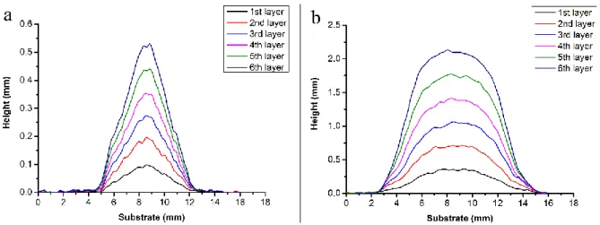
4.3.2 Simulation results and discussions... 110
VI
4.5 Conclusion ... 119
References ... 119
Chapter 5 Conclusion and prospects ... 121
5.1 Conclusion ... 122
5.2 Prospects ... 123
Annexes... 125
VII
Chapter 1 Introduction
Figure 1.1 Different thermal spraying techniques with different particle velocity and gas
temperature. ... 3
Figure 1.2 Schematic diagram of the CS system. ... 4
Figure 1.3 Kinematic parameters in the cold spraying process. ... 5
Figure 1.4 Influence of spray distance. ... 7
Figure 1.5 Schematic of spray angle. ... 8
Figure 1.6 Schematic of scanning step. ... 9
Figure 1.7 Commonly used zig-zag path in CS. ... 9
Figure 1.8 (a) Nozzle traverse speed distribution along the spiral trajectory; (b) The original and CS repaired damaged workpiece. ... 11
Figure 1.9 AM in the broad and narrow sense. ... 12
Figure 1.10 ABB IRB 2400 consisting of (a) manipulator with 6 axes and (b) controller system. ... 15
Figure 1.11 Coordinate systems of industrial robot. ... 17
Figure 1.12 Working envelope of ABB IRB 2400/16 robot. ... 18
Figure 1.13 Payload of ABB IRB 2400/16 robot. ... 19
Figure 1.14 An example of robot cooperation using robot offline programming software. ... 24
Figure 1.15 Procedure of an off-line programming. ... 27
Figure 1.16 Modules in Thermal Spray Toolkit (TST) ... 29
Figure 1.17 Spray trajectory generation under PathKit. ... 29
Figure 1.18 (a) the user interface of ProfileKit of coating profile simulation in 2D. (b) the user interface of ProfileKit of coating thickness simulation in 3D. ... 30
Chapter 2 Design and implementation of modular framework for CSAM Figure 2.1 Schematic diagram of the CSAM system. ... 41
Figure 2.2 Different nozzle for CSAM. ... 43
Figure 2.3 Different configuration manner: (a) the robot holds the spray gun; (b) the spray gun is fixed. ... 44 Figure 2.4 (a) CS deposits scanning via the 3D profilometer; (d) data collection and
VIII
Figure 2.6 Schematic representation of common HIP process. ... 49 Figure 2.7 Flowchart of CSAM process. ... 50 Figure 2.8 Triangular tessellation scheme for the production of primitive shapes . ... 53 Figure 2.9 titanium component constructed with an internal channel, prepared by dissolving aluminum . ... 53 Figure 2.10 Schematic of the fabrication process of a part manufactured using CS and topology optimization technology . ... 54 Figure 2.11 Schematic of the fabrication process of CSAM pyramidal fin arrays heat sink .
... 55 Figure 2.12 CSAM processing with RobotStudio ™. ... 56 Figure 2.13 Scheme of layer-by-layer CSAM process. ... 58 Figure 2.14 Measuring the layer morphology in real-time: (a)by normal spraying; (b) by topology technique. ... 59 Figure 2.15 (a) result of normal spraying; (b) result of the current spraying strategy (with deviations and disturbances); (c) result of on-line adaptive control. ... 59
Chapter 3 Cold spray process modeling and simulation
Figure 3.1 Coating condition of shadow effect. ... 68 Figure 3.2 Schematic of single coating profile model on X-Y plane (red line) and X1-Y1 plane (blue line). θ and β are the spray angle on X-Y plane and X1-Y1 plane respectively. a is the angle between Z axis and Z1 axis. 𝜓 is the deflection angle (the angle between Z axis and ab line, as well as AB line). 𝛾 is the angle between ab line and AB line. ... 70 Figure 3.3 (a) Creation of rays and intersection on a flat; (b) Creation of cylinders on a flat; (c) Single coating profile model on a flat; (d) Creation of rays and intersection on a non-planar; (e) Creation of cylinders on a non-planar; (f) Single coating profile model on a non-planar. ... 71 Figure 3.4 Schematic of coating thickness distribution model. ... 72 Figure 3.5 (a) Discrete single coating profile with overlaps; (b) Continuous single coating profile on a flat; (c) Continuous single coating profile on a curved surface; (d) Continuous single coating profile on a complex surface. ... 73
IX
Figure 3.7 Results of coating thickness distribution at spray angle of 90°, 80°, 70°, 60°, 50° respectively. ... 76 Figure 3.8 Effects of spray angle on weight gain and relative deposition efficiency of 7075 Al coating. ... 77 Figure 3.9 Effects of Nozzle traverse speeds (20–100 mm/s) on coating thickness and peak correction factor of Al7075 coating. ... 78 Figure 3.10 Effects of spray distance (from 10 to 45 mm) on coating thickness and relative deposition efficiency of 7075Al coating. ... 79 Figure 3.11 The user interface:(a) for basic parameters setting and coating simulation; (b) for coating simulation base on the real robot kinematic data; (c)for measuring the coating thickness; (d) for measuring the coating thickness. ... 81 Figure 3.12 Coating thickness simulation in RobotStudio™. (a) Generation of trajectory; (b) Signal of nozzle travel; (c) target points for coating thickness simulation; (d) Coating thickness distribution... 83 Figure 3.13 Calculate and measure coating thickness. (a) Coating thickness at the specified location; (b) coating cross-sectional profile. ... 84 Figure 3.14 Experimental result; (b) simulation result. ... 86 Figure 3.15 Comparison of experimental and simulation results of coating thickness. .. 87 Figure 3.16 The main view and top view of the workpiece with a shadow effect. ... 88 Figure 3.17 (a) Generation of trajectory; (b) target points for coating thickness simulation.
... 89 Figure 3.18 (a) Experimental and (b) simulation results of CS deposition on workpiece with shadow effect. ... 90 Figure 3.19 Comparison of experimental and simulation results of coating thickness at (a) cross-section 1, (b) cross-section 2 and (c) cross-section 3. ... 91
Chapter 4 Stable layer-building strategy to enhance cold spray based additive manufacturing
Figure 4.1 Schematic of particle impact conditions in cases with (a) high deposition efficiency phase and (b) low deposition efficiency phase ... 98 Figure 4.2 Schematic of the triangular-tessellation strategy proposed by J. Pattison ... 99
X
Figure 4.5 Profiles of the single tracks deposited at different numbers of nozzle pass
measured by the 3D profiler. ... 102
Figure 4.6 Effects of the number of scanning pass on relative deposition efficiency. ... 103
Figure 4.7 (a) Single tracks deposited at different nozzle traverse speed (b) Profiles of single tracks measured by the 3D profiler... 103
Figure 4.8 Effects of the nozzle traverse speed on relative deposition ratio. ... 104
Figure 4.9 (a) Single tracks deposited at different spray angles (b) Profiles of the single tracks measured by the 3D profiler. ... 105
Figure 4.10 Effects of the nozzle traverse speed on relative deposition efficiency. ... 105
Figure 4.11 Gaussian curve. ... 106
Figure 4.12 Schematic of CSAM spray strategy for thick and vertical walls... 107
Figure 4.13 Schematic of CSAM spray strategy for large blocks or thick coatings. ... 108
Figure 4.14 Schematic of simulate operation. ... 109
Figure 4.15 Lateral view of spray strategy simulation in a situation where the deflection angle was 30º (θ=30º), and the offset distance s changed. ... 110
Figure 4.16 The cross-sectional profile based on the simulation in Figure 4.15. ... 111
Figure 4.17 Lateral view of spray strategy simulation in a situation where the offset distance was 2σ (s=2σ), and the deflection angle θ changed. ... 112
Figure 4.18 The cross-sectional profile based on the simulation results in Figure 4.17. ... 113
Figure 4.19 Comparison results between appending d (the value of nozzle retreat) and without it. ... 114
Figure 4.20 The cross-sectional profile based on the simulation results in Figure 4.19. ... 114
Figure 4.21 Experiment results at the deflection angle of 30º (θ = 30º), and the offset distance was 0 mm, σ mm, 2 σ mm, 3 σ mm, 4 σ mm, respectively (s = was 0 mm, σ mm, 2 σ mm, 3 σ mm, 4 σ mm). ... 115
Figure 4.22 Experiment results at the offset distance of 2 σ mm (s= 2 σ mm), and the deflection angle was 10º, 20º, 30º, 40º, respectively (θ =10º, 20º, 30º, 40º)... 116
Figure 4.23 (a) Cross-sectional view sprayed track using optical microscope; (a′) Optical micrograph of coatings; (b) Each sprayed track morphology measured by a 3D profiler. ... 117
XI
created on a flat surface; (c) a thick and vertical curved wall was created on a flat surface; (d) a thick and vertical wall was created on a curved surface. ... 118
Annexes
Figure 6.1 Model topology. ... 127 Figure 6.2 Schematic diagram of model topology. ... 127 Figure 6.3 Shifting the position of a three-dimensional object using translation vector T.
... 130 Figure 6.4 (a) Rotation of an object about the z axis; (b) Rotation of an object about the x axis; (c) Rotation of an object about the y axis. ... 131 Figure 6.5 Scaling objects relative to the original point. ... 131 Figure 6.6 Scaling objects relative to a selected fixed point (xf, yf, zf). ... 132
XII
Table 1.1 Axis motion specification of robot ABB IRB 2400/16. ... 21 Table 3.1 Operating parameters used for effect analysis of the different robot kinematic parameters. ... 75 Table 3.2 Distance between two discrete points under different TCP speeds. ... 83 Table 3.3 Operating parameter details used for experiments. ... 85 Table 3.4 Average and standard deviation of coating thickness, as well as absolute and relative error of simulated results with experimental ones. ... 87 Table 3.5 The absolute and relative error of simulated results compared with experimental ones based on different cross-sections. ... 91 Table 4.1 Detailed description of operating parameters. ... 101 Table 4.2 Detailed description of parameters used in simulation. ... 109 Table 4.3 The relative deposition efficiency of the different deflection angle in simulation.
... 113 Table 4.4 The relative deposition efficiency of the different deflection angle in the experiment... 116
1
Chapter 1
2
1.1 Cold spray technology
In the mid-1980s, a new spraying technique called cold-gas dynamic spraying or cold spraying (CS) was initially developed by a group of scientists from the Institute of Theoretical and Applied Mechanics of the Siberian Branch of the Russian Academy of Sciences (ITAM of RAS) in Novosibirsk, Russia [1,2]. For the modern manufacturing industry, surface technology is important and necessary because it has specific abilities to provide corrosion protection, wear control, damage repair, fouling protection and temperature/oxidation protection, etc. The sprayed coating has excellence performance including structural homogeneity, high density, high purity, notable cohesive strength, and frequently moderate compressive residual stresses. As an emergent technology, CS has many advantages that makes it uniquely competitive among various thermal spraying technologies [1–4]. For example, being a non-thermal or low-temperature process, CS allows spraying thermally sensitive materials without the risk of melting, oxidation, thermal decomposition, crystallization, grain growth, or phase transformations. In addition, the high speed and energy of sprayed particles can provide high deposition efficiency. Therefore, CS has been applied to prepare various functional coatings [2,5,6] and to restore damaged metal components [7–10] as well as to fabricate freestanding metal parts [9–12]. During the deposition process, the spray gun needs to be precisely controlled to achieve the desired coating thickness or the final shape of the deposit. Thus, industrial robots have been widely used in the field of CS due to their high performance, such as high accuracy, high repeatability, high flexibility, etc.
1.1.1 Principle of cold spray
Generally speaking, CS belongs to the wide family of thermal spray technology. As shown in Figure 1.1, due to its low gas temperature and high particle velocity, CS can be separated from other thermal spray processes [2,4]. Figure 1.2 shows a typical CS system which consists of high-pressure compressed gas sources, power sources, a powder feeder, a spray gun and an industrial robot. The gas source is separated into two different gas lines: one is fed to the gas heater as propellant gas and the other is sent to the powder feeder (carrier gas) to drive the powders into the nozzle. The propellant gas can be heated. The powder feeder can provide continuous and controllable feeding. During a spraying process, metal powders with a size distribution in between 1 and 50 μm are accelerated by high-pressure gas flow through a
3
convergent-divergent de-Laval nozzle to reach a high velocity (500–1200 m/s) [2,4]. Particles remain at a temperature lower than the melting point and then impact against a solid surface to form a coating [2]. The industrial robot arm is used to perform the motion of the spray gun in order to achieve controllable, safe and accurate spraying path.
Figure 1.1 Different thermal spraying techniques with different particle velocity and gas temperature.
There are two types of operating parameters in CS: the process parameters and the parameters related to the robot motion. The process parameters generally include the feedstock data and the gas condition [13–15]. These parameters govern the in-flight behaviour of the particles as well as their deformation during the collision onto the substrate. The second category of parameters refer specifically to the kinematic parameter of the spray gun which is in fact controlled by the industrial robot via a robot trajectory programming [16–20]. In the following section, these parameters will be illustrated in details.
4
Figure 1.2 Schematic diagram of the CS system.
1.1.2 Spraying parameters in cold spray
Many publications have described the relationship between the spraying parameters and the coating characteristics as well as the coating structures [1,4,14]. Only when the pre-set spraying parameters permit the sprayed particles to reach the material-related critical speed, the particle/substrate or interparticle interfaces form a dense coating [21,22].
Generally, the propellant in CS can be air, argon, nitrogen, or helium. The gas nature has a particularly important role on the particle acceleration. Different gas sources affect the particle acceleration and impact velocity due to their different average molar mass [23–25]. For example, helium gas leads to higher increases in the particle velocity due to its lower molar mass [23]. Normally, the gas temperature and pressure refer to the parameters of the propelling gas. In CS, the maximum gas temperature is about 900°C [26]. The temperature setting is mainly determined according to the sprayed material. For example, the spraying temperature for pure copper powder is generally set in between 400-600 °C [27,28].
Since the temperature of the working gas is significantly lower than the melting point of the material, there will be no oxidation and phase change. The optimal temperature setting can not only conducive to the increase of the particle speed and the deposition efficiency, but also minimizes the effect of high temperatures on the material performance and the substrate. The
5
working gas pressure of CS is generally set in between 1.5~3.5MPa [24,26]. The working gas expands from the high pressure at the nozzle inlet to normal pressure, resulting in a supersonic airflow which varies with the nozzle structure and size, working gas type, gas pressure and temperature, powder particle size and density and other factors.
1.1.3
Kinematic parameters in cold spray
As mentioned above, industrial robots are widely used in field of CS due to their high stability and high accuracy of manipulation and motion, leading to the fact that the coating quality is affected directly by the robot kinematics [17–20]. Therefore, the CS kinematic parameters are actually a series of parameters manipulated and controlled by the robot. Figure 1.3 illustrates the general process of spraying gun motion, and the involving kinematic parameters are listed below:
o Spray trajectory
o Relative speed between nozzle and substrate o Spray distance
o Spray angle o Scanning step o Over-length
6
1.1.3.1 Spray trajectory
The spray trajectory, also called spray path, is a point set of spraying targets that are connected to each other by robotic programming. The aim of spray trajectory planning is to enable the coating to cover the entire object surface uniformly. Spray trajectory not only influences the coating thickness and distribution, but also the property of coating, especially the coating anisotropy[16,29–31]. Therefore, it is very important to plan the spraying path before spraying. With the increase of complex workpiece geometry, path programming has evolved from the initial manual manner to the current computer-aided automatic programming based on different algorithms [16,18,32], especially the usage of robot offline programming technology that improves the capability and reliability of path planning.
1.1.3.2 Nozzle traverse speed
The nozzle traverse speed is the moving speed of the robot in relation to the substrate. The relative moving speed between the nozzle and the substrate is referred to as nozzle traverse speed. The nozzle traverse speed equals to the moving speed of the robot. It is one of the most important parameters that can influence the mass distribution and the coating thickness [19,20,33]. The faster the nozzle travels, the fewer the deposited particles. Correspondingly, the coating thickness will also decrease in a certain period of time. In addition, the slower the nozzle moves, the longer the heating source exposition on the same area of the substrate surface, that leads to the deterioration of the coating quality because of local over-heating and residual stress [34–36].
In order to obtain a desired coating with uniform thickness and performance, appropriate and stable nozzle traverse speed is required. Generally, the effective moving speed of a robot during a deposition cannot be maintained at the predefined value due to the factor of inertia and motor performance. For this reason, influences of the inertia of the nozzle setup and performance limitation on the robot speed should be eliminated in spraying processes. Nowadays, some studies have been performed to improve the stability of robot performance by kinematic optimisation [37,38].
1.1.3.3 Spray distance
7
substrate surface, which will affect the particle final states reaching the substrate, and thereby the coating thickness and deposition efficiency [18].
Generally speaking, there exists a critical velocity of particle for a given material. Only the sprayed particles reaching a velocity higher than this critical value can adhere on the substrate to form a coating. As shown in Figure 1.4, the spray distance will directly influence the flight duration of particles from the nozzle exit to the substrate, and definitely affects the acceleration of particles [33,39]. There is an optimum distance for an optimum deposition efficiency [3,33]. Therefore, an appropriate value of spray distance should be defined and keep constant during the operating process.
Figure 1.4 Influence of spray distance.
1.1.3.4 Spray angle
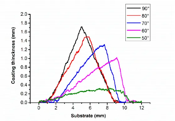
The spray angle is the angle between the nozzle and the surface of the substrate (Figure 1.5). Generally, in the CS process, the nozzle should be kept perpendicular to the substrate surface to have a maximum deposition efficiency. In Li.et al.'s report [40], the spray angle has little effect on the deposition efficiency in the angle range of 80-90°.
8
Figure 1.5 Schematic of spray angle.
In any case, it is certain that the inclined spray angle increases the particle loss and decreases the deposition efficiency due to the particle rebound during the impact on the substrate. The porosity of the coating will increase if the spray angle decreases from 90°. Therefore, the most active manner is that the spray angle should be kept at about 90°, that is easier to achieve for a plane surface. However, if the robot axes will reach their rotation limit at a certain point on the workpiece, especially for the workpiece with a complex shape, the robot has to compromise the spray angle to obtain a smoother scanning speed and coating quality. This has been proved to be feasible [40]. The spray angle between 90° and 45° is considered acceptable by striking a balance between deposition efficiency and the coating quality.
1.1.3.5 Scanning step
The scanning step refers to the interval between two successive scanning tracks when a coating is deposited by a multi-track trajectory (Figure 1.6). It is the key factor for the flatness and the thickness of a coating. The optimal value of the scanning step can result in a uniform coating. If the scan step is too small, the coating surface roughness will become rather low. If the scan step is too large, the flatness of coating will be decreased and the coating thickness distribution will become uneven. Besides, different scanning steps will lead to the different distribution of the track-to-track profile, thereby affecting the distribution of residual stress and pores [41,42].
9
Figure 1.6 Schematic of scanning step.
1.1.3.6 Over-length
Generally, in the spraying processes, a round-trip alternating path is always used to scan the entire surface, such as the commonly used zig-zag path, as shown in Figure 1.7. Here, a part of the trajectory that exceeds the boundary of the workpiece is a parameter called over-length. When changing the scanning direction in between two successive passes, the robot will go through a process of deceleration and re-acceleration in order to overcome its own inertia and the weight of the nozzle. Therefore, it is necessary to reserve a certain over-length to allow the robot to re-reach the predefined speed to ensure a constant robot speed in the surface area of the substrate. It is required to avoid unnecessary waste of materials by choosing an appropriate value of over-length.
10
1.1.4 Applications of cold spray
As mentioned above, CS is a newly developed solid-state deposition technique that allows conversion of powders into a solid coating structure without local melting, phase transformation, grain growth, etc. Nowadays, CS has been widely applied as a coating technology in a broad range of industries, including aerospace, automotive, energy, medical, marine and other fields [2,9,10] .
CSed deposits provide effective protection against high temperature, corrosion, erosion, oxidation and chemicals [4]. For example, the CSed Al-5% Mg coating is a viable corrosion coating on ZE41A-T5 magnesium [43]. The Ni-20Cr cold-spray coating is very useful in developing high-temperature oxidation resistance for T22 and SA 516 boiler steels [44]. With the development of CS technology, the fundamentals of the process are now better understood and more available equipment has been developed to better perform this manipulation. Except for preparing various functional coatings, CS can be used for reconstruction or repair of damaged metal components or to fabricate free-standing metal components [9,10,45]. In the next parts, CS based repairing and additive manufacturing will be introduced respectively.
1.1.4.1 Cold spray repair
With the rapid development of modern industrial sectors, many long-term important components suffer from varying degrees of damage due to corrosion, collision, wear, fatigue, or other reasons. They have to be removed from service. However, replacing or producing a new part will likely lead to high costs and time-consuming, that would encourage companies to renew the damaged components instead of replacing them. As a result, developing economically sustainable and highly reliable maintenance services and repair strategies are paid more attention.
Nowadays, there are several types of metal manufacturing technology that have been used for the remanufacturing of parts, like laser metal deposition (LMD) [46,47] and selective laser melting (SLM) [48,49], as well as laser beam build-up welding [50,51], etc. However, among these techniques, high-power electron beams or high-frequency laser radiations are used for heating or melting materials but can lead to unsatisfactory results such as oxidations, grain growth, residual thermal stresses, and phase transformations.
11
repair of damaged metal components, especially in the aircraft industry. Compared to other repair methods (laser beam build-up welding, metal inert gas welding, and laser cladding), CS enables the recovery of defective areas without thermally affecting the base material and is proven as a cost-effective repair process [9,10]. To date, it has been successfully applied to repair various damaged components due to its capability to avoid any thermal damage to the underlying substrate material, and unique ability to retain the original properties of the feedstock powder.
Typical examples are restorations of a mechanically damaged gas turbines of an aircraft [52], reconditioning the housings of oil pumps on aircraft engines [53], refurbishment of a damaged aluminium hydraulic valve body [54] and worn aluminium mold [45], etc. In a recent work, a special spiral trajectory was developed for repairing damaged parts with cold spray [29]. Figure 1.8 shows this spiral trajectory and a repaired coupon. The specific trajectory is composed of two opposite spirals, one for entering and the other exit, which ensures the stable movement of the robot during repair, and thus provides a uniform coating. This method can match the coating with the original damaged defect shape to avoid excessive material deposition and to reduce post-processing work. In this work, the spiral trajectory included various nozzle traverses speed in inverse proportion to the crater depth to produce a homogenous deposit and to save feedstock.
Figure 1.8 (a) Nozzle traverse speed distribution along the spiral trajectory; (b) The original and CS repaired damaged workpiece.
1.1.4.2 Cold spray based additive manufacturing
Additive manufacturing (AM), also called rapid manufacturing or 3D printing, is the general term for a series of technologies that build 3D objects by adding materials layer by layer (whether the material is plastic, metal, concrete or human tissue). In 1981, the Nagoya
12
Municipal Industrial Research Institute came up with an idea of 3D printing inspired by a photo-hardening polymer technology [55]. Note that the term 3D printing began to be used around 1993 when the Massachusetts Institute of Technology developed the first powder bed process using inkjet print heads [56].
AM uses the gradual accumulation of materials to manufacture solid parts, which is different from traditional material removal-cutting technology. What AM technology has in common is the use of computers, 3D modeling software (computer-aided design or CAD), special machinery and equipment, and layering materials. Once the CAD sketch is generated, the AM device reads the data from the CAD file and lays down or adds successive layers of liquid, powder, sheet material or other materials in a layer-by-layer manner to create a 3D object [57]. As the development of AM, technology practitioners have put forward the concepts of narrow and generalized AM (Figure 1.9 [58])). Narrow sense AM is a series of technologies characterized by the combination of different energy sources and CAD/CAM technology, layering and accumulating materials, such as selective laser melting (SLM) [59,60] and selective laser sintering (SLS) [61], as well as wire and arc additive manufacturing (WAAM) [62], etc. The generalized AM is a relatively broad technology group, which is based on the accumulation of materials and aims to directly manufacture parts of various sizes. Such a typical process is thermal spraying, physical vapor deposition (PVD) [63] or electro-chemical deposition [64], etc. In addition, according to the type and method of processing materials, AM can be divided into metal forming, non-metal forming, and bio-material forming.
13
Nowadays, metal-related AM technology has become the focus of the global industry. CS has attracted much attention because of its great potential in solid-state forming metal components. In fact, this technology now is regarded as a potentially competitive AM due to the ability to build 3D objects when the CS gun is attached to a robot. Nowadays, with the development of technology, it has gradually occupied its place in the field of AM. In comparison with other AM technologies, many advantages make it unique in fabricating freestanding metal components. For example, CS processes can deposit temperature-sensitive materials without phase transformation or grain growth. Moreover, CS can be used for the fabrication of multi-material and gradient deposits, and its high production efficiency is expected to make breakthrough in the rapid manufacturing of large parts. To date, some companies or research institutions have intensively invested in the CSAM process and have achieved various results. For example, General Electric company (GE) builds large amounts of components for aviation’s jet engines by using the CSAM system. They also used two robots to produce large metal components for the first time, where one robot held the component and moved it to a precise position, while the other one held the spray gun to spray materials on the component [65]. Titomic company has adopted the CS process to spray titanium or titanium alloy materials onto a scaffold to produce a load-bearing structure [66]. There is no doubt that CSAM will be more widely used in the field of direct metal manufacturing and will eventually develop and innovate in the direction of commercialisation.
All the CS applications, especially CS based repair and AM, require precise control of the kinematic parameters during the spraying process. These parameters not only ensure the feasibility of CS based applications, but also the quality of the CSed deposits, including geometry and mechanical properties. Therefore, the application of industrial robots in CS is particularly important. The next section will introduce industrial robots in detail.
1.2 Industrial robot
Generally, a robot is a machine capable of carrying out a complex series of actions automatically. It is often used to replace humans to complete a certain task, especially in those repetitive and dangerous tasks that humans are not suitable for, or are unable to do because of the size limitations or even those extreme environments such as outer space or deep ocean. Nowadays, many different kinds of robot have been developed affecting the way people live and work, such as industrial robots, mobile robots, collaborative robots, biomorphic robots,
14
military robots and so on. Among these categories, industrial robots are currently the most widely used and most mature one.
Since the United States developed the world's first industrial robot in 1962, industrial robot technology and its products have developed rapidly, and are now widely adopted in the field of industrial manufacturing and processing [67]. Typical applications of industrial robots include welding, painting, packing, assembly, stacking, product inspection and testing, which are accomplished with high efficiency and precision. As long as the process is well programmed and prepared, productivity can be improved largely by robots.
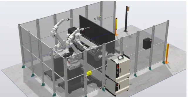
In the field of CS and thermal spraying, a spray gun is usually attached to a robot's end-effector to deposit materials on the substrate surface. Stable and precisely control on CS parameters is important and necessary for a desirable coating. Robot-assisted CS system allows the precision and stability performance that manual operating cannot meet. Last but not least, industrial robots can protect operators without potential harm resulting from the extreme working environment such as high temperature, noise, dust.
Commonly used industrial robots include FUNUC Robots, MOTOMAN Robots, ABB Robots and KUKA Robots, etc. In this thesis, all spraying processes are performed by an ABB IRB2400-16 robot. In this section, Multi-axis robot system, as well as its basic performance, will be introduced.
1.2.1 Multi-axis robot system
The Multi-axis robot system is an automatically controlled, reprogrammable, multipurpose manipulator with three or more axes. Generally, the number of axes for a simple manipulator such as a CNC machine is in between 2 and 3, and in between 3 and 6 for the programmable robots [67]. Besides, the degree of freedom is equal to the number of axes. Therefore, multi-axis robot system with greater number of axes can perform more complex actions and tasks. Figure 1.10 shows a typical 6-axis robot system which mainly consists of two parts including the manipulator and its controller system.
15
Figure 1.10 ABB IRB 2400 consisting of (a) manipulator with 6 axes and (b) controller system.
The manipulator is the six-axis robot body. As shown in Figure 1.10 (a) [68], Axis 1, located at the robot base, allows the robot to rotate from left to right; Axis 2 is the axis powering the movement of the entire lower arm, which allows the lower arm of the robot to extend forward and backward; Axis 3 allows the upper arm to raise and lower as well as to reach behind the body, extending the robot's work envelope; Axis 4 allows rotating the upper arm in a circular motion; Axis 5 is responsible for the pitch and yaw motion, allowing the wrist of the robot arm, to tilt up and down; Axis 6 is responsible for a twisting motion. It allows rotating freely with a capacity of more than a 360-degree rotation in either clockwise or counter-clockwise direction. There is a flange on the sixth axis, which can be used to attach tools like welding devices, spray guns, grinding and deburring devices, grippers and so on.
In addition, the controller system contains a control cabinet and its electronics, which are mainly used to control the manipulator, external axes and other peripheral equipment, etc. As shown in Figure 1.10 (b), a teach pendant connected with the control cabinet is used to display robot status, to control and program robot motion. Operators can use the joystick or buttons on the teach pendant to move the robot with a defined speed. Besides, robot programs prepared on the PC can also be synchronized to the robot control system via the disk drive shown in Figure 1.10 (b), and displayed on the screen of teach pendant. In the following section, basic performances of multi-axis robot system will be presented in detail.
16
1.2.2 Robot technical specification
1.2.2.1 Degree of freedom
Degree of freedom refers to the freedom of movement of a rigid body in three-dimensional space. Specifically, the body is free to change its position forward or backward (surge), up or down (heave), left or right (sway) in three perpendicular axes, combined with changes in orientation through rotation about three perpendicular axes, often termed yaw (normal axis), pitch (transverse axis), and roll (longitudinal axis) [66]. In a mechanic context, the number of degrees of freedom is equal to the total number of independent displacements or aspects of motion, and can also be regarded as the number of axes. A typical industrial robot used in CS or in thermal spray has a six degree of freedom (Figure 1.10).
1.2.2.2 Robot coordinate systems
The coordinate system is important for any industrial robot to perform a proper motion. Generally, the coordinate system as defined by geometry includes Cartesian Coordinate System, Polar Coordinate System, Cylindrical, or Spherical Coordinate Systems. Industrial robots with 6 degrees of freedom mostly use the Cartesian Coordinate System. Figure.1.11 shows five coordinate systems used in robot system, including world coordinates, base coordinates, tool coordinates, user coordinates and object coordinates [69]. The detailed definitions are as follows:
17
Figure 1.11 Coordinate systems of industrial robot.
The world coordinate system defines a reference to the floor which is the starting point for the other coordinate systems. People often use the origin of the robot base as world coordinate system. Therefore, the world coordinate system generally equals to the base coordinate system. Base coordinate system is the base framework attached to the base of the robot. Itdefines the position of the base relative to the world coordinate system.
The tool coordinate system is freely definable. It is attached to the end of arm of tooling. When no tool has been installed on the robot, the origin of the coordinate system is at the center of the robot's sixth axis flange. The origin of the tool coordinate system is called Tool Center Point (TCP) and is used for tools. In CS applications, especially in AM or repair, TCP needs to be redefined, and its position is usually defined at the impact point on the substrate, which is located on the projection line from the nozzle outlet, considering the pre-set spray distance. Besides, there are two different programming ways for the use of TCP. If the spray gun is attached to the robot, TCP will be defined as being held by the robot and moving with the robot during the spraying process. If the spray gun is fixed at an appropriate position while the substrate or the formed part attaches to the robot, TCP will not be defined as being held by the robot and kept stationary at the defined position.
18
The user coordinate system specifies the position of a fixture or a workpiece manipulator. It can be defined as a movable user coordinate system if a work object is placed on an external mechanical unit. The object coordinate system specifies how a workpiece is positioned in a fixture or a workpiece manipulator.
1.2.2.3 Working envelop
A robot's work envelope refers to the working volume which can be reached by the center of the end effector of the Robot arm. In other words, it is the maximum overall area within which the robot arm can move. Figure 1.12 displays the working envelop of ABB IRB 2400/16 robot [68]. This shape is created when the robot reaches forward, backward, up and down. So, the robot's range of movement depends on the different robot properties such as length/diameter of each joint component. What is more, the working envelope is important for a particular application. For CS applications, the trajectory and the robot's motion should be controlled within the limits of the working envelop.
Figure 1.12 Working envelop of ABB IRB 2400/16 robot.
1.2.2.4 Payload
Robot payload or carrying capacity is the weight a robot arm can lift, that is based on the size of the robot and the power of the actuator. Therefore, it is very important to consider the robot application when determining the maximum payload. For safety reasons, the total weight,
19
including the tools installed on the end effector of the robot cannot exceed the maximum payload of the robot. It should be noted that the maximum payload is not a constant value and depends on the size of the tool, or exactly, the position of the tool's gravity centre.
As shown in Figure 1.13, it illustrates the maximum weight permitted for load mounting on the mounting flange at different positions of a robot IRB 2400/16 from ABB Company [68], where L is the distance in X-Y plane from Z-axis to the gravity centre. The maximum own moment of inertia on the total handling weight also should be considered. These parameters can be found in advance in the corresponding Robotics Technical Manual.
Figure 1.13 Payload of ABB IRB 2400/16 robot.
1.2.2.5 Speed
The robot speed mentioned here refers to the linear speed of the TCP moving around in the world coordinate system frame. Similarly to the other robot specifications, the robot speed is a very important characteristic for evaluating the robot performance, depending on the size, power, and other features of the robot. Ordinarily, the robot speed and the rotation speed of
20
each axis have their limits. If the distance for acceleration or deceleration is not enough, the robot could not reach the predefined speed. However, the constant or smooth motion of the robot is very important for lots of applications including spraying, painting and welding, etc. The robot speed that deviates from the predefined value cannot ensure product quality. Therefore, it is very important to ensure a constant robot speed concerning robot kinematics.
Actually, in CS, different nozzle traverse speeds are applied according to the desired coating thickness and the specific application. For example, the nozzle traverse speed is chosen from 40 mm/s up to 200 mm/s [33] generally to achieve a full coating deposition. Sometimes, a nozzle traverse speed [70] as high as 500 mm/s is used to obtain the single-particle deposition on the substrate, which is used for the study of bonding mechanism and particle deformation behavior. However, during CS, the path direction constantly changes to cover the entire surface of the substrate. Especially when performing some complex spraying path, the robot speed cannot maintain a constant predefined speed. As a result, it is essential to optimize the robotic kinematics parameters or to find a compromise between robot speed and spray angle.
1.2.2.6 Joint motion
The desired angles or positions of the end-effector motion is achieved by moving all the robot joints. The motion state of each axis of the robot can be described through three indicators: joint position, joint velocity, and joint acceleration. For the joint position, it represents the value of axis rotation at a given time, with a unit of degree. Normally, each axis of the robot has its corresponding rotation limit. Table 1.1 lists the axis motion specification of robot ABB IRB 2400/16 [68]. It can be found that axis 6 permits the largest range of motion, while axis 3 permits the smallest range. The joint position of each axis decides the TCP position and orientation within the working envelop. A smooth changing of the joint position within its rotation limit is conducive to a better axis motion performance. Otherwise, it will cause the axis servo motor to spend more energy to complete the robot motion, that will cause more fluctuations of the TCP speed.
The joint speed is the angular speed of an axis with a unit of degree per second (°/s). It is defined by the derivative of the joint position with respect to time. As another variable to evaluate the axis performance, the joint speed represents how fast an axis rotates, whose limit is based on the servomotor performance. As shown in Table 1.1, each axis of the robot has its corresponding joint speed. And axis 6 has the maximum axis speed, that is, this axis has the
21
most sensitive motion performance. Similarly, a sudden changing of the joint speed will increase the load on the control system and will probably reach the limit of the drive system.
Table 1.1 Axis motion specification of robot ABB IRB 2400/16.
Axis Range of Movement, Maximum axis speed, /s Maximum axis acceleration, /s² 1 +180 to -180 150 298.734 2 +110 to -100 150 84.959 3 +65 to -60 150 356.740 4 +200 to -200 360 638.927 5 +120 to -120 360 637.599 6 +400 to -400 450 830.221
In addition. the joint acceleration is to evaluate how joint speed varies, with a unit of °/s2. Generally, the greater the acceleration of the joint, the faster the response of the axis to the corresponding command, and the higher the accuracy. However, the servo motor must provide greater power to obtain the larger joint acceleration that is required to achieve the desired speed, and this has a certain impact on the mechanical longevity of the system. In other words, lower joint acceleration or sustained joint acceleration can reduce mechanical wear. Moreover, the three indicators of the joint are related to each other. In order to improve the robot performance and maintain the TCP speed, it is important to make sure that all the joint positions are within limits. Besides, the joint speed of all axes is constant or smoothly changes.
1.2.3 Robot programming
Compared to traditional machines, the main advantage of industrial robots is their programmability. Robots can perform arbitrary sequences of predefined motions. In CS applications, the main task of the industrial robot is to execute the spraying trajectory with high precision. The planning and generation of the spraying trajectories are based on the shape of the workpiece to be sprayed and different operating parameters. Thus, an efficient and proper programming method is necessary for trajectory generation and post-analysis.
Currently, the methods of robotic programming involve the on-line teaching [71] and off-line programming [16,19]. The choice of the method to use mainly depends on the type and
22
complexity of the project. Most robot programming uses an online teaching method, which is appropriate and efficient for certain simple tasks. However, for those complex movements that require higher accuracy, offline programming should be used to define the robot's movement in order to perform tasks that cannot be accomplished by on-line teaching method. In this section, these two methods of robotic programming will be presented.
1.2.3.1 On-line programming technique
Industrial robots generally consist of three parts: a controller, a robot arm, and a teach pendant [67,68]. The teach pendant is the remote controller of the robot, which is equipped with a user operation interface software and buttons, moving handles, touch screen, etc. The operator controls the robot to complete the specified actions through these human-computer interaction functions. This process is called online programming or teaching programming. Traditionally, it is the most commonly used robotic programming method in most industries.
In general, the tool and its assembly are first installed on the end-effector of robot (wrist). A Tool Center Point (TCP) should be defined based on the tool and the task, that is usually located at the end of the tool or at the point of contact. The operator uses the manual control on the teach pendant to control the robot and moves the TCP to the desired position, and then stores the information of the position in a series of motion commands (including the position and orientation of the TCP). After storing all target points and robot motion commands, the corresponding trajectory program can be then tested. It is worth mentioning that industrial robots have good position repeatability, that is, after teaching, the robot can run the same program repeatedly, and the accuracy of returning to the same spatial position point can reach the level of ten microns to hundreds of microns.
The advantages of this programming method are its low learning cost and easy use. In the process of online programming process, operators are required to perform on-site operations in the working unit of the robot. However, since this method requires many manually operated robot movements, the programming process will be tedious and time-consuming. Depending on the complexity of the task, this may take days or even weeks. In addition, the robot needs to leave the production line during online programming so the production will be interrupted. Generally, online robot programming requires experienced engineers to debug on-site and run the program repeatedly to achieve the desired effect. For CS, the working range of the spray gun, the nozzle travel speed, the spray distance and the spray angle, etc, need to be considered
23
for the programming. However, for tasks that require high complexity and accuracy as well asrepeated modifications, the online programming method may not be suitable. Thus, the next section will introduce the second programming method, called offline programming method, which aims to handle complex programming tasks.
1.2.3.2 Off-line programming technique
Robot offline programming refers to "virtual" programming of the robot on the computer (PC) through related software tools [72,73]. Programmers need to use CAD models to offer a more scientific programming strategy. This process includes creating CAD models, robot path planning, creating motion programs, and robot motion simulation. When using this method for programming, there is no need to stop the robot in production, so it will not hinder the production operations.
With the development of robot technology and the continuous expansion of its application fields, offline programming technology has gradually become a popular programming method, which is mainly used to complete some complex programming tasks. Currently, this technology has been widely used in welding, laser cutting, thermal spraying, CNC machining and other fields, to deal with some complex programming tasks. In conclusion, the robotic off-line programming technology provides a complete solution for industrial robots, from trajectory generation, parameter selection to process simulation and trajectory optimization. The trajectory of the robot can be generated by using the geometric data of the workpiece to ensure the accuracy of the trajectory, and at the same time provides more optimization strategies while reducing also the occurrence of collision accidents.
Robot offline programming technology is even more essential in CS application. First of all, an accurate and reasonable spray trajectory is a necessary condition for ideal coatings. The robot offline programming technology can provide optimized spraying path and reliable programming [16,19]. In addition, for complex shapes, online programming is difficult to complete with the correct definition of the trajectory point. During the spraying process, it must ensure that the spraying direction is perpendicular to the surface of the workpiece, and at the same time it must ensure also that the coating can evenly cover the entire surface of the workpiece. Offline programming is an accurate programming method based on the CAD model. This allows the robot to easily adjust the tool operation direction and the starting pose of the robot to avoid the singularity state and obtain the most optimized path.
24
In addition, CS is not only used to prepare various functional coatings on the surface of various complex parts as a coating technique, but also to repair various damaged metal components as a repair technology, and to fabricate freestanding metal parts as an AM technology. Since many applications are no longer just a process of producing simple coatings, Computer-aided design (CAD) and Computer-aided manufacturing (CAM) are needed to provide the ideal spray strategy, including generating trajectories, simulating the process and collision detection. Robot offline programming technology can be used as a new production capacity and modernization application to provide desirable solutions in the process. The next section will introduce application software used for offline programming.
1.3 Robot off-line programming software
Robot offline programming technology requires the application of related software systems, called robot offline programming software [72]. Many robot manufacturers have developed their own robot offline programming systems compatible with their robots. The software operator can create a three-dimensional virtual scene of the entire actual workstation and uses the related functions provided by the software to accomplish many programming tasks that cannot be completed by online programming. As shown in Figure.1.14, this is a typical case of cooperation between multirobot using offline programming technology.
Figure 1.14 An example of robot cooperation using robot offline programming software. Nowadays, there is various robot offline programming software used in the world. For example, RobotStudio™ is a powerful off-line programming software developed by Asea
25
Brown Bovrie Ltd (ABB) that enables very realistic simulations of robot motion[69]; RobotMaster [74] is an offline programming software developed by Hypertherm Robot Software Co that is compatible with most robot brands on the market, including KUKA, ABB, Fanuc, Motoman, Panasonic, etc. and integrates advanced functions including robot programming, simulation and code generation functions. In the following section, we will introduce RobotStudio™, which is the offline programming software used for the studies in this thesis.
1.3.1 RobotStudio™
RobotStudio ™ is a commercial software provided by ABB company. It is specifically developed for performing robotic tasks including programming, trajectory simulation, and collision detection, etc. RobotStudio™ is based on ABB Virtual Controller technology, which is the same as a software embedded and running in real robots [69]. The technique makes it possible to graphically create a virtual robotic site like the real site. Therefore, users can use the software to specify the robot's motion, automatically form executable code and then synchronize it to the actual robot. RobotStudio ™ provides the ability to design the robot program in a computer with a learning programming method. The advantages of RobotStudio ™ are as below:
All types of robot models of ABB products are available in the Robot system library. Commonly used geometric models such as STL, IGES, STEP, ASCII, ACIS and CATIA can be imported directly into RobotStudio ™ as digital components for modeling.
Robotic programming and simulation including the detection of collisions in the graphic environment ensure the safety of the operator and the equipment.
The program is designed and created in a computer so that it can be prepared in advance even though the robot is still in production.
RobotStudio™ provides an interface for users to personalize development according to specific requirements.
Figure 1.15 shows the general process of programming using RobotStudio™, which is suitable for various industrial applications, including CS.
• Generally, the first step is to establish a virtual workstation with the same configuration as the actual spray shop, including the same type of robot, spray gun and tools, and the
26
same placement between the various elements. The advantage of the virtual robot workstation is that it can truly reflect the actual spraying process. In addition, it is convenient to change the spraying procedure at any time and observe whether the various components interfere with each other, thereby preventing collisions between the equipment effectively.
• Then, the CAD model of the workpiece to be processed is imported into the corresponding virtual robot workstation and is placed in the operation position. • After that, a tool coordinate system should be defined, known as the tool centre point
(TCP), to specify the tool’s centre point position and its orientation.
• Then, a workpiece coordinate system, also called workobject, is used to define workpiece origin and coordinate orientation. Each position is specified in the workobject coordinate. This means that even if a fixture or workpiece is moved, only the workobject coordinate system needs to be redefined, then all the defined points will be revised accordingly. Besides, if a tool is replaced, the original program can still be used, unchanged, by making a new definition of the tool.
• The next step is to create a robot trajectory with the help of CAD files.It is easier and more accurate to obtain and define a target point position, which will result in a trajectory with higher precision.
• After generating the robot trajectory, simulation can be carried out through the function of the simulation module in Robotstudio. According to the results of the simulation, the robot trajectory and the process strategy can be adjusted in the feedback loop to achieve the desired result.
• Once the trajectory of the robot is confirmed, the corresponding program can be downloaded to the actual robot system for calibration, testing and application.
27
28
1.3.2 Necessity of auxiliary system for cold spray application
Generally, RobotStudio™ or other offline programming software can meet the needs of general applications. Operators can generate an appropriate trajectory according to the CAD model of the workpiece. For example, the trajectory can be easily created on a curved intersection or an edge of the workpiece for the application of welding or cutting. As for CS process, the trajectory consists of paths separated by the constant scan step to guarantee that the coating covers the entire surface of the substrate. Besides, for the purpose of high coating quality, several operating parameters including spray angle and spray distance must be constant. The nozzle should be perpendicular to the substrate surface to ensure high deposition efficiency.
However, it is not easy to create parallel spray paths on curved substrate surfaces, which is time-consuming and lacks precision even under off-line programming software. Moreover, CS based additive repair or manufacturing is no longer a process of producing simple coatings but requires more and advanced and complicated paths to meet various spraying tasks. Exactly, CS repair needs to generate a trajectory that matches the original damaged defect shape in order to avoid excessive material deposition and reduce post-processing work, and CSAM needs to create a shaping path adapting CS characteristics. Obviously, the basic function including trajectory generation in RobotStudio™ cannot meet the above-mentioned cases.
Therefore, in order to satisfy the specific requirements of the new application in the CS, it is necessary to develop software based on the off-line programming platform to provide the appropriate spray strategy quickly and precisely. RobotStudio™ allows the developers to develop different kind of custom applications or Add-Ins as a new feature in its application. LERMPS (Laboratoire d’Etudes et de Recherches sur les Matériaux, les Procédés et les Surfaces) has developed an add-in application program named Thermal Spray Toolkit (TST) in the framework of RobotStudio™ [16,20]. In the next part, the main functions of TST will be briefly presented.
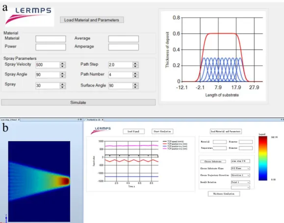
1.3.3 Thermal Spray Toolkit (TST)
TST is a RobotStudio™ based extension software developed for the generation of trajectory in thermal spray applications, and all its functions are also suitable for CS. Figure 1.16 shows the four basic modules of TST.
29
Figure 1.16 Modules in Thermal Spray Toolkit (TST)
Here, PathKit enables the creation of robotic trajectories according to the geometry of workpiece. In this module, one method is presented using orthogonal planes to cut the substrate surface, then a series of scanning curves can be generated. Meanwhile, the normal vector is calculated to define the orientation of the nozzle on every point of the curves. PathKit uses this method to generate robot trajectories for thermal spraying in the offline programming software RobotStudio™ [75,76]. It can automatically and quickly generate trajectories according to the shape of the workpiece that meets the required operating parameters (as shown in the Figure 1.17).
Figure 1.17 Spray trajectory generation under PathKit.
ProfileKit module is developed for the purpose of the coating deposition simulation. Currently, a coating thickness model based on the numerical method was developed and was

![Figure 2.8 Triangular tessellation scheme for the production of primitive shapes [27]](https://thumb-eu.123doks.com/thumbv2/123doknet/14552628.725799/68.892.211.684.101.460/figure-triangular-tessellation-scheme-production-primitive-shapes.webp)
![Figure 2.10 Schematic of the fabrication process of a part manufactured using CS and topology optimization technology [30]](https://thumb-eu.123doks.com/thumbv2/123doknet/14552628.725799/69.892.219.677.156.935/figure-schematic-fabrication-process-manufactured-topology-optimization-technology.webp)
![Figure 2.11 Schematic of the fabrication process of CSAM pyramidal fin arrays heat sink [31]](https://thumb-eu.123doks.com/thumbv2/123doknet/14552628.725799/70.892.186.711.107.366/figure-schematic-fabrication-process-csam-pyramidal-arrays-heat.webp)