HAL Id: tel-01756399
https://tel.archives-ouvertes.fr/tel-01756399v2
Submitted on 14 May 2018HAL is a multi-disciplinary open access
archive for the deposit and dissemination of sci-entific research documents, whether they are pub-lished or not. The documents may come from teaching and research institutions in France or abroad, or from public or private research centers.
L’archive ouverte pluridisciplinaire HAL, est destinée au dépôt et à la diffusion de documents scientifiques de niveau recherche, publiés ou non, émanant des établissements d’enseignement et de recherche français ou étrangers, des laboratoires publics ou privés.
Development of new dosimetric standards for low energy
X-rays (
≤ 50 keV) used in contact radiotherapy
Abdullah Abudra’A
To cite this version:
Abdullah Abudra’A. Development of new dosimetric standards for low energy X-rays (≤ 50 keV) used in contact radiotherapy. Nuclear Experiment [nucl-ex]. Université Paris-Saclay, 2017. English. �NNT : 2017SACLS489�. �tel-01756399v2�
Development of new dosimetric
standards for low energy X-rays
(≤ 50 keV) used in contact radiotherapy
Thèse de doctorat de l'Université Paris-Saclay préparée à l’université Paris-Sud École doctorale n°576 : Particules Hadrons Energie et Noyau, Instrumentation, Image, Cosmos et Simulation (PHENIICS) Spécialité de doctorat : Radio et Hadron-thérapies
Thèse présentée et soutenue à Gif-sur-Yvette, le 11/12/2017, par
Abdullah ABUDRA’A
Composition du Jury :Marc VERDERI Président
Directeur de recherche, Ecole Polytechnique Laboratoire Leprince-Ringuet (Palaiseau)
Aurélie DESBREE Rapporteur
Ingénieur chercheur, Institut de Radioprotection et de Sûreté Nucléaire (IRSN) - Laboratoire d’Evaluation de la Dose Interne (Fontenay-aux-Roses)
Régine GSCHWIND Rapporteur
Professeur des universités, Université de Franche-Comté Laboratoire Chrono-Environnement UMR (Montbéliard)
Albert LISBONA Examinateur
Physicien médical, Institut de cancérologie de l’Ouest Centre René Gauducheau (Saint Herblain)
Ramona ITTI Examinateur
Physicien médical, Hôpital Saint Louis
Service de Cancérologie et Radiothérapie (Paris)
Isabelle AUBINEAU-LANIECE Directeur de thèse
Professeur, Commissariat à l'énergie atomique et aux énergies alternatives - CEA saclay/LIST/ LNHB (Gif-Sur-Yvette)
Christel STIEN Invité
Ingénieur chercheur, Commissariat à l'énergie atomique et aux énergies alternatives - CEA saclay/LIST/ LNHB (Gif-Sur-Yvette) NNT : 2 0 1 7 S A CL S 4 8 9
Université Paris-Saclay
Espace Technologique / Immeuble Discovery
Route de l’Orme aux Merisiers RD 128 / 91190 Saint-Aubin, France
Titre : Développement d'une référence métrologique pour les faisceaux X de basse énergie utilisés en radiothérapie de contact Mots clés : Radiothérapie de contact, référence primaire, curiethérapie électronique, RX de basses énergies INTRABEAM®
Résumé : La curiethérapie électronique, également appelée radiothérapie de contact, est une technique de traitement du cancer utilisant
des rayons X de faible énergie (≤ 50 keV) générés par des tubes à rayons X miniaturisés et positionnés au contact des tissus à irradier. La miniaturisation des générateurs à rayons X a conduit au développement de nouveaux systèmes de traitement, dont le plus répandu dans le monde et le seul utilisé en France est le système INTRABEAM® commercialisé par la société Zeiss. Au-delà du bénéfice médical, les
avantages potentiels de la curiethérapie électronique sont une diminution drastique de l'inconfort du patient combinée à un moindre coût de traitement. Ainsi, dans le cadre du cancer du sein qui correspond à l’application principale de l’INTRABEAM, cette technique remplace la trentaine de séances de radiothérapie externe classiquement prescrite suite à l’exérèse du volume tumoral par une seule et unique séance délivrée en 20 à 50 minutes au bloc opératoire directement après l’acte chirurgical alors que la patiente est encore sous anesthésie. Cette radiothérapie peropératoire (RTPO) associe au mini générateur de rayons X des applicateurs qui, en sénologie, correspondent à des sphères de différents diamètres conçues pour épouser au mieux la cavité tumorale résultant de l’exérèse. La dose délivrée en RTPO est classiquement de l'ordre de 20 Gy en surface du lit tumoral et diminue rapidement avec la profondeur afin de préserver les tissus sains voisins (< 1 Gy après quelques cm). En France, le 1er traitement par RTPO a eu lieu à Nantes fin 2011.
Aujourd’hui, une dizaine de centres hospitaliers français propose des traitements par RTPO au moyen de la technique INTRABEAM®.
Très rapidement, plusieurs physiciens médicaux ont exprimé au laboratoire français de métrologie de la dose (LNHB), leur besoin de raccordement dosimétrique à une référence indépendante du constructeur. Ce besoin a été réaffirmé par la Haute Autorité de Santé (HAS) dans un rapport sur l’évaluation de la RTPO dans le cancer du sein, édité en avril 2016.
Le présent travail vise à renforcer la sécurité d’emploi d’appareils de RTPO par rayons X de basse énergie (< 50 keV). Cependant, afin de répondre aux physiciens médicaux français et du fait de contraintes temporelles, l’étude est ici limitée au système INTRABEAM associé au seul applicateur sphérique de 4 cm de diamètre. Le travail a été articulé autour de trois axes.
Le premier a concerné l’établissement et le transfert d’une référence primaire en termes de dose absorbée dans l’eau à 1 cm de profondeur. La méthodologie a été développée et ensuite appliquée pour le système INTRABEAM® associé à un applicateur sphérique de 4 cm, pour
lequel, la référence primaire a été réalisée.
Le deuxième axe a eu pour objet la détermination de la distribution spatiale de dose autour de la source considérée par l’utilisation de gels dosimétriques et par calcul de type Monte Carlo. L’hydrogel à base de Fricke, utilisé ici, est lu par imagerie par résonance magnétique à l’hôpital d’Orsay. Ce gel a été étalonné en dose pour des photons d’énergie inférieure à 50 keV puis utilisé pour déterminer les profils de doses autour de la source INTRABEAM® associée à l’applicateur sphérique de 4 cm de diamètre dans les plans axial et transverse
incluant le centre de la source INTRABEAM®.
Quant au dernier axe, il s’est agi de confronter des données dosimétriques fournies par la société Zeiss, concernant l’INTRABEAM® en
utilisation à l’hôpital St-Louis à Paris, à celles obtenues au cours de la présente étude pour le même système. Des différences
significatives ont été trouvées entre les doses délivrées par Zeiss et celles obtenues dans la présente étude. Une étude indépendante menée par le PTB pour une autre configuration de source INTRABEAM® a conduit à des observations comparables. L’approche adoptée par
Zeiss a ainsi été investiguée dans le présent travail et une cause de divergence a été proposée.
Title: Development of new dosimetric standards for low energy X-rays (≤ 50 keV) used in contact radiotherapy Keywords: Electronic brachytherapy, Primary standards, Low-energy X-rays, INTRABEAM®
Abstract: Electronic Brachytherapy (eBT), also called contact radiotherapy, is a cancer treatment technique using low energy X-Rays (≤
50 keV) generated by X-Ray tubes which are placed in close contact with the treated lesions. The latest evolutions of miniaturized X-Ray tubes led to the development of new treatment systems, such as the INTRABEAM® system of the ZEISS Company which is the most
available eBT system and the only one currently used in France. Beside its medical benefit, the potential major advantages of treatment by eBT are the drastic decrease in patient discomfort and treatment cost. In the case of breast cancer treatment with such technique, the treatment is given in a single session that lasts 20 to 50 minutes where a high dose, in the order of 20 Gy, is delivered to the tumor bed surface in contact with spherical applicators associated to the X-Ray source. The delivered dose decreases rapidly with depth (< 1 Gy after a few centimeters) enabling to preserve neighboring healthy tissues. In France, the first IORT treatment performed was in Nantes in 2011. Today, ten medical centers offer IORT treatment using the INTRABEAM® system. Consequently, several medical physicists addressed to
the French national metrology laboratory for ionizing radiation (LNHB) their need for a dosimetric traceability with a reference
independent from the manufacturer. This need was reaffirmed by the French Authority for Health (HAS), in their report on the evaluation of the IORT for breast cancer treatment published in April 2016.
This thesis work is a contribution to the metrological work initiated by LNHB for enhancing the safety of employing IORT by eBT systems. It was limited, within the thesis period, to the INTRABEAM® system associated with a 4 cm diameter spherical applicator. The
thesis work was oriented towards three main objectives.
The first one concerned the establishment and the transfer of a primary dosimetric standard, in terms of absorbed dose to water at 1 cm depth in water. The methodology was developed and applied on the INTRABEAM® system with 4 cm spherical applicator, for which, the
dosimetric reference was established.
The second objective was to use a dosimetric gel and the Monte Carlo method to assess the 3D spatial distribution of the relative absorbed dose delivered by such a system. The dosimetric gel system used was a Fricke-based hydrogel read by Magnetic Resonance Imaging at Service Hospitalier Frédéric Joliot in Orsay (SHFJ). The gel reading was calibrated, in terms of absorbed dose for low energy X-Rays (< 50 keV), and then used to define the relative dose distributions of the INTRABEAM® X-Ray source associated with the 4 cm spherical
applicator in the axial and transverse planes of the X-Ray source probe tip.
The last objective was to compare the dosimetric data delivered by Zeiss, for the INTRABEAM® system used at St. Louis hospital in
Paris, by the ones obtained in the current study for the same system. Significant discrepancies were found from this comparison between the doses delivered by Zeiss and those obtained in the current study. Discrepancies were also observed in a separate work conducted by the PTB under a different INTRABEAM® configuration. Some reasons of these discrepancies are outlined and discussed in this study.
Acknowledgments
Et voilà, it’s the end of this “adventure”. An adventure that I was so glad to start yet thrilled to finish. Actually, it’s so bizarre this feeling, once you’re in, you strive to pop out, and once it’s done, you want to jump back in. Well ... in fact, not really!
Several persons have actually participated, in a way or another, to accomplish this work. Words succeed most of time to express gratitude yet falls drastically when comes to certain persons who leaves you out of words. At least, I’ll do my best!
I would like to express my appreciation to Valentin BLIDEANU, director of “laboratiore de métrologie de la dose (LMD)”, and Loïc LE NOIR DE CARLAN, director of “Henri Becquerel National Laboratory (LNHB)”, for giving me the chance to get into this adventure and to be part of the LNHB/LMD team. I’m also so grateful for the cancerology & radiotherapy service at Saint Louis hospital in Paris for giving us an access to their INTRABEAM® system, and more practically, for madam Ramona ITTI for all the help and expertise she provided for this work.
I would like also to express my deep gratitude to Isabelle AUBINEAU-LANIECE, my research supervisor, Marc DENOZIERE and Christel STIEN, my research tutors, for their patient guidance, enthusiastic encouragement and useful critiques on this research work. Also, with a great respect and acknowledgement, I thank the jury members for the time and efforts they conferred to examine this work.
I wish to acknowledge the help and demonstrations provided by Jean and Juan in the field of Monte Carlo simulations, and the rich discussions and guidance led by Johan “Le HdO” in the fields of instrumentations, spectroscopy, and DIY (bricolage); See how beautiful the measurement systems we have developed together! Know what, they exist, Really! … no, no I don’t mean the aliens, even more exceptional! I mean these wise characters who escort you throughout adventures as in fairytales! He’s one of them, Bruno CHAUVENET. Actually, without him, this work would not have been accomplished. THANK YOU SO MUCH Bruno.
I want to extend my gratitude to all my colleagues at LMD for their kindness and help, for the work environment they have, and for all the good moments we spent together. I will definitely always remember the funny and warm-hearted Nelly & the “petit” discussions with you Dominique.
The shiny brilliant funny colorful and helpful couple (Fabien & Mélanie). You guys are so adorable. You actually are one of the best things I had through my thesis. Thanks for everything 😊
The Ph.D. title looks cool, huh… in fact what even cooler are the moments you live and the experience you share with your Ph.D. compatriots. I want to thank “le Capitaine” Stéphane, Sybelle and Isabelle with whom I shared the first months of my thesis, Héléna for all the good, and bad, stories we shared together. As well, the whole wonderful international group of “homeless fellas” and especially the kind Monika (keep us impressed with your artistic nail-polish), LiVia (with a V this time and not an F), Alessia (el bella italiana), Oscardo, Aninda, Hector, Bianca, Mohcine, Mario, Anshuman and surely my precious buddy Malik Shukeir (it’s been 11 years already, and wherever I go, it’s a pleasure to find him there!). To the three awesome Post-docs, Nadia & Anne-Laure (les superb Mamies) and Guillaume, who have been always present to share lovely discussions during the coffee-breaks, and beyond 😉 many many thanks.
They say “True friends never apart, maybe in distance but never in heart”. I totally agree, and hence, I want to thank my beloved friends: Alaa Al-Najjar, Obada Al-Ali, Mutaz Kalabani, Khamees Al-Jazarah, Nabrawi, Abdullah Darwish, and the trio Hussam and Ayman² for their constant supportive calls and messages. I have particularly appreciated your travel to be present at my defense beautiful Mireeeeen & Pierre, and you priceless Gryffindor gang, thanks for being always around.
I want to thank each one in my Jordanian family here in France: Laith (le parrain), Hazim, Fadous, Hussam, Mutaz, Lara, Tasneem, Malik, Rania, Nassima, Rostum, Wafa (the best storyteller) and my valuable “host-family” Jordan and Malak.
To the special person who accompanied me along this adventure: the fastidious French teacher, the TripAdvisor, the friend and lover… for every part you fill in my life, Merci Alice.
I thought I was the happiest, once I finished this adventure, till I called my parents… The enormous delight they had in their voices recalled me how my life is completely different just because they are always by my side. My treasure: elder brother Mohammed (one of a kind) and Montaha, Ibrahim & Ruba, Ahmed & Tahani, Suad & Mohammed and you our “little” Fatin, I am so lucky for having you all. At last, for sure, I won’t forget the kitties and teddy bears of my big family: Sarah, Tala, Layan, Ahmed (Sultan) and the last, but not the least, the brand-new little angel, P’tit Abdullah.
I might have forgot to thank you, yes you who’s reading these lines, by name in the previous lines, I am really sorry, and believe me, I’ll be so happy to thank you in person!
To the heroes fighting against cancer
…
anywhere and in any manner, we’ve never been closer to defeat this
intruder… So, never cease, even for a single instant, before winning
Table of contents
INTRODUCTION ...
5Chapter 1: Materials and methods ...
81.1. Intraoperative radiotherapy by electronic brachytherapy
...
81.1.1. Electronic brachytherapy (contact X-Ray therapy) ... 8
1.1.2. Conventional and miniature X-Ray generators (purpose and principles)... 9
1.1.3. Available systems and sources ... 10
1.1.4. INTRABEAM® system by Carl ZEISS ... 12
1.2. Dosimetric quantities ... 14
1.2.1. Air kerma (Kair) ... 14
1.2.2. Absorbed dose (D) ... 15
1.2.3. Relation between kerma and absorbed dose (charged-particle equilibrium) ... 15
1.2.4. Low-energy photon specificities (dosimetry of low-energy photons) ... 16
1.3. Dosimetry of kilovoltage X-Ray beams ... 16
1.3.1. Primary standards for low-energy X-Ray beams ... 17
1.3.2. Secondary dose measurements – transfer chambers ... 19
1.3.3. Relative dose measurements (1, 2 or 3D) ... 20
1.3.3.1. Detectors for 1D and 2D dose measurements ... 20
1.3.3.2. 3D dose measurements ... 21
1.3.3.3. The gel dosimetry method used for this study ... 25
1.3.3.3.1. Gel characteristics and principle... 25
1.3.3.3.2. Magnetic Resonance Imaging (MRI) ... 26
1.3.3.3.3. Principle of R2 determination ... 28
1.3.4. X-Ray beams spectrometry ... 29
1.3.5. Monte Carlo simulations ... 30
1.4. Dose metrology of low-energy photon beams ... 31
1.4.1. The metrological chain of traceability for dosimetric quantities ... 32
1.4.1.1. Different actors ... 32
1.4.1.2. Reference beam qualities and HVLs ... 33
1.4.2. Metrological traceability of IORT beams ... 34
1.4.2.1. Indirect traceability – Application of existing protocols ... 34
1.4.2.3.1. IAEA - TRS 277 & 398 ... 34
2
1.4.2.2. Direct traceability (for electronic brachytherapy) ... 35
1.4.2.3.1. PTB-CMI calibration method ... 35
1.4.2.3.2. NIST calibration method (for AXXENT) ... 37
1.4.2.3. Dosimetry and calibration of the IB-XRS with spherical applicators by Zeiss ... 38
Chapter 2: Establishment and transfer of a dosimetric reference in terms of
absorbed dose to water at 1 cm in water D
w,1cm ... 422.1. Methodology adopted to realize the dosimetric reference, Dw, 1cm, for the INTRABEAM® source with spherical applicators... 43
2.2. Characterization & reproduction of IB spectra at LNHB ... 45
2.2.1. Measurements of IB photon energy spectra ... 45
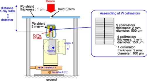
2.2.1.1. Measurement setups ... 46
2.2.1.2. Photon energy spectra... 48
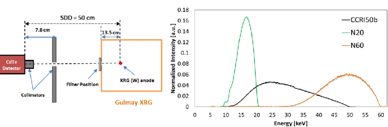
2.2.2. Reproduction of the IB spectra by the conventional XRG at LNHB ... 50
2.2.2.1. Choice and calculations of adequate filters for each spectrum... 51
2.2.2.2. Measurement of reproduced spectra ... 51
2.2.3. Comparison and equivalence of reproduced spectra to those of IB ... 52
2.3. Developing a MC model of the IB-XRS with a spherical applicator of 4 cm in diameter .... 53
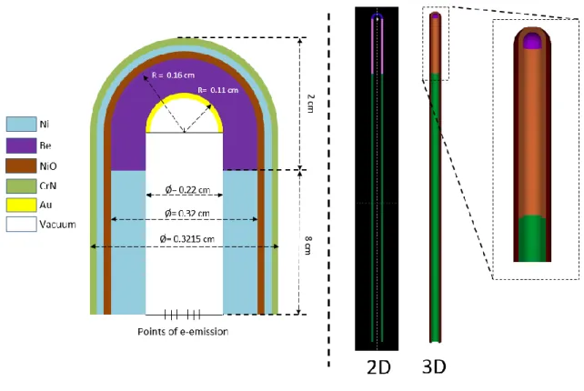
2.3.1. Modeling of the IB-XRS and of the 4 cm applicator ... 54
2.3.1.1. Geometries and materials ... 54
2.3.1.2. Materials and simulation parameters ... 56
2.3.2. Validation of the MC model ... 58
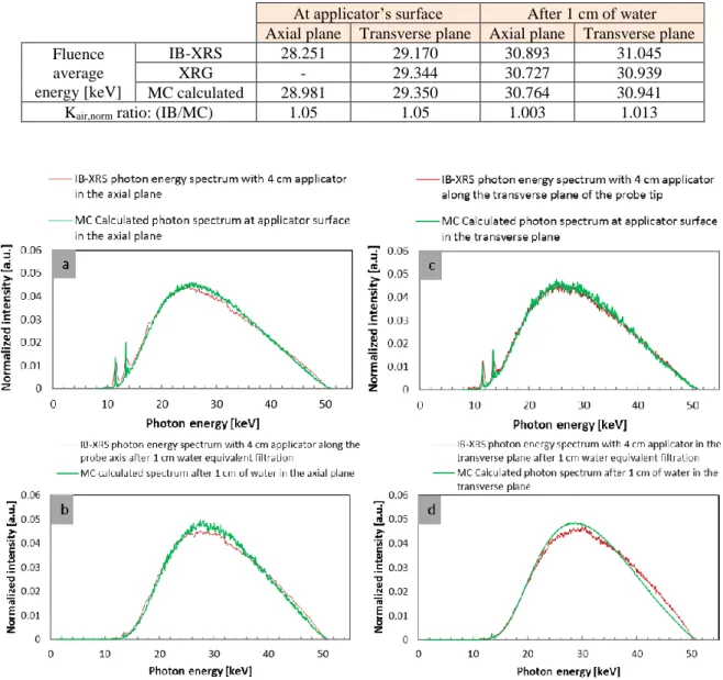
2.3.2.1. Calculations of beams at surface and after 1 cm of water ... 58
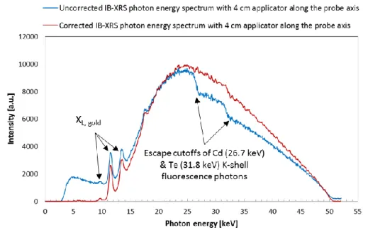
2.3.2.2. Comparison of the MC calculated to the measured IB spectra ... 59
2.3.3. PSF creation ... 61
2.4. Determination of 𝐷𝑤, 1𝑐𝑚 for IB with 4 cm spherical applicator ... 61
2.4.1. Determination of the reference air kerma rate, 𝐾air, ref ... 61
2.4.1.1. Using correction factors determined with the conventional method ... 63
2.4.1.2. Using a global correction factor calculated by MC simulations ... 63
2.4.1.3. Results and comparison ... 65
2.4.2. Calibration of transfer ionization chambers under reproduced INTRABEAM beams . 67 2.4.3. Measurements of INTRABEAM 𝐾air, IB𝑚𝑒𝑎𝑠𝑢𝑟𝑒𝑑 ... 69
2.4.4. MC calculations of the conversion factor, 𝐹(𝐾air, IB to 𝐷w, 1 cm) ... 73
2.4.4.1. Calculation of 𝐾air, IBMC under measurement conditions ... 73
2.4.4.2. Calculation of 𝐷w, 1cm𝑀𝐶 along the probe axis ... 76
2.4.5. Calculation of the absorbed dose rate to water at 1 cm ... 79
3
Chapter 3: Determination of the absorbed dose profiles around the IB-XRS
using a dosimetric gel ...
843.1. Calibration of the dosimetric gel ... 84
3.1.1. Calibration methodology ... 85
3.1.2. Experimental design ... 87
3.1.2.1. Choice of beam qualities ... 87
3.1.2.2. Air kerma rate of the chosen beams ... 87
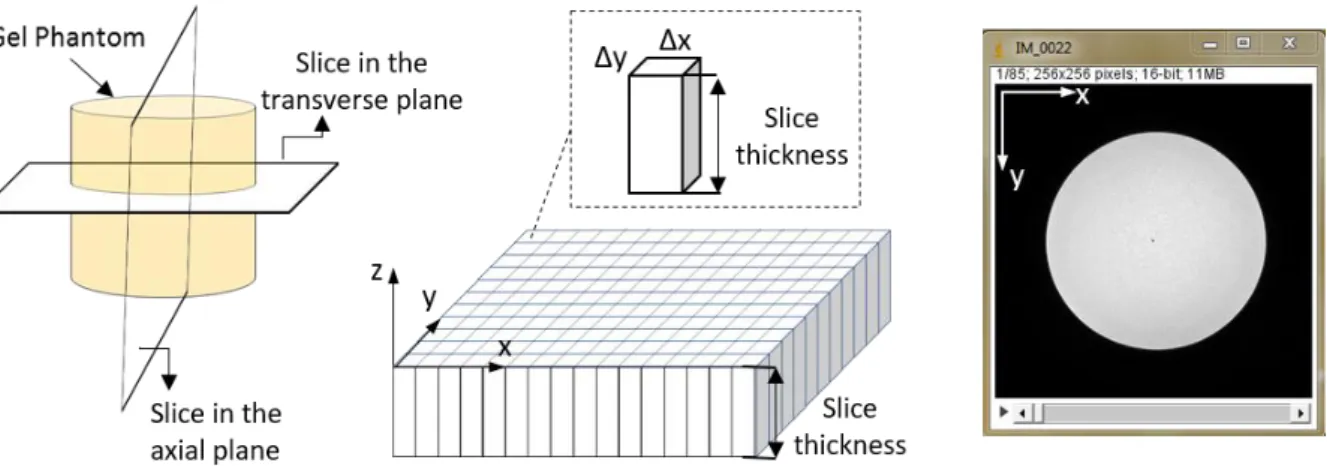
3.1.2.3. Gel phantoms design ... 88
3.1.3. Determination of 𝑅2(𝑧) ... 89
3.1.3.1. Preparation and irradiation of gel phantoms... 89
3.1.3.2. Phantoms reading by MRI ... 90
3.1.3.3. Calculations of 𝑅2(𝑧) ... 92
3.1.4. Determination of the absorbed dose profiles 𝐷gel(𝑧) in gel phantoms ... 95
3.1.4.1. MC calculation of 𝐷gel, MC(𝑧) and 𝐸(𝑧) ... 95
3.1.4.2. MC calculation of 𝐾air, MC ... 98
3.1.4.3. Determination of 𝐷gel(𝑧) ... 99
3.1.5. Establishment of the calibration curve ... 101
3.1.5.1. Calculation of R2,0 values ... 101
3.1.5.2. Determination of ∆𝑅2(𝑧) values and gel calibration ... 102
3.2. Absorbed dose profiles in gel around the IB-XRS ... 105
3.2.1. Phantom design, gel preparation and irradiation ... 105
3.2.2. Gel response reading by RMI ... 106
3.2.3. Correction for the B1-field inhomogeneity ... 108
3.2.4. Determination of the absorbed dose profiles in gel ... 109
3.3. Absorbed dose profiles in water around the IB-XRS ... 111
3.3.1. MC calculation of the relative absorbed dose to gel profiles and validation of the calibration procedure ... 111
3.3.2. MC calculation of conversion factors to go from gel to water dose profiles ... 113
3.3.3. Determination of the absorbed dose profiles in water ... 113
Summary ... 117
Chapter 4: Analysis of the INTRABEAM® dosimetric methods and dose
distributions ...
1204.1. Comparison of INTRABEAM® doses to the LNHB and the PTB-CMI primary standards 120 4.2. Analysis of the absorbed dose to water method, TARGIT, provided by ZEISS ... 122
4 4.2.2. Absorbed dose to water determination by the methods used by Zeiss for the
INTRABEAM® dosimetry ... 124
4.2.3. Comparison between the two methods (expressions 1 and 2) ... 124
4.2.4. Conclusions on the comparison ... 125
4.3. Confrontation of the absolute dose distributions established in the present work with the ones delivered by the Zeiss Company ... 126
4.3.1. Determination of absolute dose distributions ... 127
4.3.2. Comparison of the dose distributions of the current study to the one delivered by ZEISS ... ... 127
Summary ... 129
General Conclusion and perspectives ...
131References
...
135APPENDIX-A ...
143APPENDIX-B ...
145APPENDIX-C...
146APPENDIX-D ...
148 D.1. Rectangular ROI ... 148 D.2. Annular ROI ... 149APPENDIX-E ...
1525
INTRODUCTION
Electronic BrachyTherapy (eBT), also called contact radiotherapy, is a cancer treatment technique using low energy X-Rays (≤ 50 keV) generated by X-Ray tubes which are placed in close contact with the treated lesions. The latest evolutions of miniaturized X-Ray tubes led to the development of new treatment systems, such as the INTRABEAM® system manufactured by the Company ZEISS. The INTRABEAM® is the most available eBT system in the world and the only one used in France.
Beside its medical benefit, the potential major advantages of treatment by eBT are the drastic decrease in patient discomfort and treatment cost. In addition, in the case of breast cancer treatment, which is the main application of the INTRABEAM®, the treatment is applied after the lumpectomy, when the patient is still under general anesthesia in the operating room; that is why eBT is considered as an IntraOperative RadioTherapy (IORT) technique. The treatment is given in a single session that lasts 20 to 50 minutes. This is equivalent to the about 30 regular sessions classically prescribed for treatment with an external radiotherapy technique.
In IORT treatment of breast cancer by eBT, spherical applicators of different sizes, intended to fit into the cavity left after tumor excision, are mounted on miniaturized X-Ray generators. A high dose, in the order of 20 Gy, is delivered to the tumor bed surface in contact with the applicator. The dose decreases rapidly with depth (< 1 Gy after a few centimeters) enabling to preserve neighboring healthy tissues. In France, the first IORT treatment performed was in Nantes in 2011, while today, ten medical centers offer IORT treatment using the INTRABEAM® system. Consequently, several medical physicists addressed to the French national metrology laboratory for ionizing radiation (LNHB) their need for a dosimetric traceability with a reference independent from the manufacturer. This need was reaffirmed by the French Authority for Health (HAS), in their report on the evaluation of the IORT for breast cancer treatment published in April 2016.
This work is a contribution to the metrological work initiated by the LNHB for enhancing the safety of employing IORT by eBT systems. However, in order to respond to the need of French medical physicists within the time constraints of a thesis, the study was limited to the INTRABEAM® system associated with a 4-cm in diameter, spherical applicator.
The thesis work was oriented towards three main objectives: the first objective was the establishment and the transfer of a primary dosimetric standard, in terms of absorbed dose to water at 1 cm depth in water, the second objective was to use a dosimetric gel and the Monte Carlo method to assess the 3D spatial distribution of the relative absorbed dose delivered by such a system and the last objective was to compare the dosimetric data delivered by Zeiss, for the INTRABEAM® system used at St. Louis hospital in Paris, with the ones obtained in the current study for the same system.
This manuscript presents the work realized in response to these objectives, it is divided into four main chapters:
• The first chapter, named “Materials and methods”, gives a global view on the IORT technique using eBT systems with a focus on the INTRABEAM®. It reminds the main dosimetric quantities and dosimetry principles related to the kilovoltage X-Ray beams.
6 The metrology of low energy photons comprising the different available dosimetry protocols, dose traceability and established primary standards for eBT systems are lastly presented.
• The second chapter covers the first objective. It describes the methodology adopted to realize the dosimetric reference for the INTRABEAM® source with spherical applicators. It presents the different steps completed to determine the dosimetric reference for the INTRABEAM® system associated with a 4-cm spherical applicator. The characterization and reproduction of INTRABEAM® photonspectra at LNHB, as well as the development of a MC model of the INTRABEAM® X-Ray source with a 4-cm spherical applicator, are presented in this chapter.
• The third chapter deals with the second objective. The methodology developed to characterize and calibrate the dosimetric gel in the photon low-energy range, and the resulting calibration function are detailed. The calibrated gel was then used to define the relative absorbed dose profiles in gel and water around the INTRABEAM® X-Ray source with a 4-cm spherical applicator.
• The fourth and last chapter addresses the last objective. The dose values obtained according to the manufacturer’s procedure for the INTRABEAM® system were compared to those determined by the LNHB primary standard. To complete the confrontation of the dosimetric data delivered by the Zeiss Company, some data involving another comparison performed by the PTB using its primary standard and considering a bare miniaturized X-Ray INTRABEAM source were also considered. On this basis, a further analysis was performed on the “TARGIT” method used originally by ZEISS for the INTRABEAM® dosimetry. Finally, the dose distributions established in the present work with the ones delivered by Zeiss were confronted.
These chapters are followed by a general conclusion and some perspectives concerning the future evolutions and improvements of the current work.
7
Chapter 1
8
1. Materials and methods
1.1. Intraoperative radiotherapy by electronic brachytherapy
The clinical applications of radiation therapy have a major role in cancer treatment. Each radiotherapy technique aims at having specific advantages over the others. The treatment cost, period, efficiency and patient’s comfort are amongst main goals intended by all techniques. A main challenge of all treatments is to deliver the highest dose to tumor cells while leaving healthy tissues spared.
IntraOperative RadioTherapy (IORT), as the name implies, is a radiotherapy technique where irradiation is delivered during surgery. A high dose, in the order of 10-20 Gy, is delivered in a single session to the surgically exposed internal organ, tumor or tumor bed. The IORT can be applied with other treatment modalities, such as chemotherapy and external beam radiotherapy that are used to shrink the tumor, and hence, simplifying the subsequent surgical resection [1].
Since the first use of IORT in the 1960s [2], different modalities relying on the IORT technique have been developed, such as Intraoperative Electron Radiotherapy, High Dose Rate brachytherapy, Orthovoltage IORT and electronic brachytherapy (low kilovoltage) IORT. Intraoperative radiotherapy using electrons has been the favored approach over orthovoltage beams because of better dose homogeneity, decreased treatment time and less bone absorption attributed to the photoelectric effect. However, orthovoltage IORT has advantages in certain clinical settings and is generally more cost-effective. Recently, electronic brachytherapy devices have become commercially available [3]. This later technique will be discussed in more detail in the next section.
1.1.1. Electronic brachytherapy (contact X-Ray therapy)
Brachytherapy (the Greek prefix “brachy” literally means “short”, “close” or “near”) techniques were firstly developed in the 1930s using radioactive sources. The name was adopted since the radiation source, used in treatment, is placed in contact, or close to the tissues to be treated. Lately, due to the development of small-sized electronic X-Ray generators, which replaced the radioactive sources, a new name was settled, i.e. electronic BrachyTherapy (eBT) or, as also called, contact X-Ray therapy.
Electronic Brachytherapy (eBT) is a cancer treatment technique, in which, the irradiator material, comprising an X-Ray generator and a variety of applicators (each applicator corresponds to a type of treatment), is placed in direct, or close, contact with the tumor. eBT uses the radiobiological properties of low-energy X-Rays, emitted by an X-Ray generator with a high voltage (≤ 50 kV) to treat cancer.
The latest evolutions of X-Ray tubes rehabilitated the interest of clinicians. It empowered the replacement of radioactive sources used in the treatment of certain types of cancer by brachytherapy techniques. For the last ten years, it has been the subject of clinical studies through which its efficiency was proven for intraoperative treatments of breast cancers [4]. Beside its medical benefit, the potential major advantages of eBT are: less requirements for protective shielding (low energy X-Rays) during the treatment and increased radiobiological
9 effectiveness [5]. It also allows to drastically decrease patient discomfort, treatment duration and cost [6].
1.1.2. Conventional and miniature X-Ray generators (purpose and
principles)
Since their discovery by W. Röntgen in 1895, numerous applications of X-Rays have been demonstrated and implemented. X-Ray generators have also evolved, and are currently used in a variety of domains including medicine.
The concept of X-Ray generators is still almost the same since its development in the late 19th century. An X-Ray tube is a simple vacuum (~10-6 mbar) tube that contains a cathode and an anode under an electric potential difference, as described in Figure 1.1 (left). The tube current (expressed in milliamperes [mA]) passes through the cathode filament to produce electrons by thermoelectrical effect (thermionic emission). Under the effect of the electric potential applied to the X-Ray tube, these electrons are accelerated towards the anode, where they decelerate, which leads to the emission of X-Rays and heating up the anode. The high voltage (HV) value determines the quality (penetrability) of the generated X-Rays, and the tube current determines the quantity of emitted X-Rays (photon flux).
Figure 1.1. Schemes of (left) an X-Ray tube (image extracted from Jacaranda Physics 1 [7]) and (right) a target atom showing the four possible X-Ray production cases: events (1-3) result in bremsstrahlung production with the emission of a continuous energy spectrum of X-Ray photons, event 4 demonstrates characteristic radiation emission [8].
The emitted X-Rays are distributed in energy according to a continuous spectrum with some discrete peaks. When the highly energetic electrons interact with the X-Ray tube anode, they lose their kinetic energy, partially or totally, as demonstrated in Figure 1.1 (right). This loss in energy is caused either by the interaction with the nucleus or an inner-shell electron. The interaction with the nucleus results in the conversion of the kinetic energy into electromagnetic radiation known as bremsstrahlung (or braking radiation). The interaction distance results in different amounts of energy loss (higher close to the nucleus). The emitted X-Ray photons then form a continuous energy spectrum up to a maximum energy corresponding to the initial kinetic energy of the most energetic electrons. The interaction with an inner-shell electron removes it from the atom; this is consequently followed by an atomic electron rearrangement and the emission of discrete-energy X-Ray photons. These photons are characteristic for each element,
10 and contribute to the X-Ray spectrum in the form of monoenergetic peaks added to the continuous spectrum.
Miniaturized X-Ray Tubes have emerged as a cutting-edge application of nanotechnology, possessing massive potential for use in various important fields, including precision medical therapy. Miniature X-Ray tubes deliver high doses from the closest possible distance. The word “miniature” implies “very small” and refers to the tube size. Some authors define that “miniature” refers to a tube size of less than 10 mm diameter [9].
The operating principle of miniature X-Ray tubes is almost the same as the conventional X-Ray tubes. However, in addition to thermionic emission, cold emission cathodes, based on field-electron (FE) emission technique, are also used. FE emission refers to the extraction of a free electron from a non-insulating solid surface exposed to a high electric field. FE is based on the phenomenon of electron tunneling where an electron penetrates through a potential barrier due to the large applied electric field. Since this process has a weak dependence on the temperature of the emitter, FE is also known as cold emission and subsequently the FE cathodes are called cold cathodes.
The miniaturizing of thermionic emission X-Ray tubes has been achieved by using thermionic dispenser cathodes. The dispenser cathodes have a limited lifetime in non-ultrahigh vacuum at which X-Ray tubes are generally operated. Indeed, this type of electron sources interacts with the residual gas molecules, leading to the deactivation of the emitter and thus to the limitation of its lifetime. The necessary prerequisite for fabricating a miniaturized X-Ray tube able to work for a large number of hours is therefore to employ a cold cathode made of one of the most common materials used as FE X-Ray sources such as carbon nanotubes [10], and other carbon nanomaterials, e.g., carbon nanofibers.
A variety of clinical systems are now available for treatment using eBT, each of them has its own miniature X-Ray generator and corresponding applicators. The next section describes several available eBT systems employing miniature X-Ray generator.
1.1.3. Available systems and sources
Over the past decades, eBT systems have seen a remarkable development. More than 400 systems are now available worldwide. The operating parameters differ from one manufacturer to another. Table 1.1 gives a summary of the existing systems and some of their operational parameters while Figure 1.2 shows their spectral distributions and the radial dose functions of some devices. Information given in this part mostly relies on the review article of D. J Eaton (2015) [11].
eBT devices were barely used until the 1960s when the Philips RT50 (Philips Healthcare, Amsterdam, Netherlands) was produced and made available on the market. This device was intended for endocavitary treatment of rectum and skin cancers. While it was progressively abandoned, the Papillon 50 contact radiotherapy system (Ariane Medical Systems Ltd, Derby, UK), with a collimated X-Ray source, was developed and then released in 2008 to replace the RT50. In the Papillon 50, electrons are accelerated into an evacuated copper tube to hit a rhenium transmission target. Photons are then produced in an approximately isotropic distribution but collimated by cones of increasing diameter to give a fixed aperture angle of 45°. A dose of 90 Gy to the tissue surface in three fractions is delivered by an “internal superficial” method where the applicator end is inserted into the rectum and placed against the lesion.
11 Seventeen applicators for skin lesions treatment are also available whereas breast IORT is under development.
The Xoft® Axxent® system (iCAD Inac., Nashua, New Hamphire, USA) is a miniature X-Ray tube integrated with a cooling sheath into a multi-lumen catheter, first released in 2006. The position of the source may be stepped along the length of the catheter, as for a high dose rate (HDR) radioactive source. Unlike the INTRABEAM® system described below, Xoft® sources have a limited lifetime of about 3 hours or 10 treatments. However, the dose rate is higher and the depth dose falls off less steeply. Source strength is verified using an internal well chamber before each treatment. Balloon catheters are used to treat early stage breast cancer with IORT. Dose distributions are similar to the MammoSite® balloon catheter (Cytec Industries Inc., Mountain View, California, USA) used with iridium-192 (192Ir) HDR sources. Multiple studies have described the dosimetric characteristics for different applicators [12–14].
The Esteya® eBT system (Elekta AB-Nucletron, Stockholm, Sweden) is a mobile collimated miniature X-Ray source released in late 2013 and designed specifically for treatment of skin lesions. Surface applicators with a flattening filter are used to give a dose distribution similar to the Valencia 192Ir HDR applicator, produced by the same manufacturer. The tube current is varied to give an approximately constant treatment time. The dosimetry of the unit has been described by Garcia-Martinez et al. [15]. They found that the flatness and symmetry of the system were within 5 %, along with a sharper penumbra and shallower depth dose than the Valencia or Leipzig HDR applicators (Elekta AB-Nucletron).
Figure 1.2. (Left) photon energy spectra of different electronic brachytherapy devices normalized to the value at 35 keV (except for iodine-125). (Right) Radial dose functions normalized to the value at 1 cm distance. Data collected from different sources and presented in the review article of D.J Eaton [11].
Photoelectric therapy (Xstrahl Ltd, Camberley, UK) is a new product launched in late 2014, also aimed at treating skin lesions. This system is a compact ultralight mobile unit with built-in cooling, easy-to-shape collimation and flattening filters to give a uniform dose profile.
Finally, the SRT-100™ (Sensus Healthcare, Boca Raton, Florida, USA) is another mobile collimated low-kilovoltage unit specifically aimed at treating skin lesions, but with focus-to-skin distance (FSD) and field sizes comparable to a standard kilovoltage therapy unit, such as the Xstrahl 100 or 150 series. This device is an example of the overlap between conventional superficial units and eBT devices.
12 Table 1.1. Operating parameters and usage of current eBT systems, clinical applications in bold refer to the primary application of the machine. These data are extracted from D. J Eaton article [11].
Machine name Approx. # of units worldwide Clinical applications Approximate treatment time Accelerating potential, tube current Geometry INTRABEAM® 250 Skin, Breast, Intracranial, Kyphoplasty, other 25-40 min (sphere) & 5-30 min (surface) applicators 50 kV, 0.04 mA Point source (probe tip)
Xoft® >150 Skin, Breast, Vaginal 10-25 min (balloon), 5-10 (surface) and 10-15 min (endocavitary) 50 kV, 0.3 mA Point source (catheter)
Papillon 11 Rectum, Skin,
Breast 2 min 50 kV, 2.7 mA Collimated source
Esteya® 10 Skin 2 min 70 kV, 0.5-1.6
mA Collimated source
Photoelectric
therapy 1 Skin 1-2 min 80 kV, 1.3 mA Collimated source
SRT-100™ 150 Skin 1-2 min 50-100 kV,
8-10 mA Collimated source
1.1.4. INTRABEAM® system by Carl ZEISS
The ZEISS INTRABEAM®(Carl Zeiss Surgical GmbH, Oberkochen, Germany) system is a compact mobile X-Ray source originally used in the treatment of brain tumors in the early 1990’s [16]. It has subsequently been used for other indications, after the development of its applicators, and since 1998 it is primarily used for IORT of breast cancer [2]. It is composed of a miniaturized X-Ray generator (XRS-4), a floor stand ensuring a precise and easy positioning of the irradiation head in the patient’s body and a user terminal connected to a control console, to set and monitor treatment parameters and to communicate data, as shown on Figure 1.3. In addition, a quality control equipment are also supplied with the system [17].
Figure 1.3. (Left) INTRABEAM® Floor stand. (Right, top), X-Ray generator of the INTRABEAM system. (Right,
bottom) Control Unit PRS 500 controlling and monitoring the XRS-4 miniaturized linear accelerator (X-Ray generator) during the treatment.
13 Electrons emitted by a heated cathode wire are accelerated to a potential of 50 kV (40 kV potential is also accessible) and collimated using an electromagnetic deflector. The resulting electron beam is then guided through a 10 cm long probe (external Ø = 3.2 mm) toward a gold target, of a thickness of 1 µm, covering the inner surface of the hemispherical probe tip. Finally, the interactions of electrons with the gold target lead to the production of X-Rays in an approximately 4π distribution, as seen in Figure 1.4.
Figure 1.4. (Left) schematic of the INTRABEAM X-Ray miniaturized generator; (right) external dose distributions of the needle applicator in water. (Data taken from zeiss.com)
Different sizes and shapes of applicators allow to treat different types of cancer, i.e. gastrointestinal [18], spinal metastasis [19] and skin [20,21]. The treatment times depend on the chosen applicator size and prescribed dose (10-20 Gy) and vary between 2 to 50 minutes. The dosimetry and quality assurance of the INTRABEAM® system have been reviewed in different publications [17,22,23].
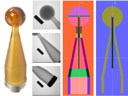
INTRABEAM® spherical applicators are used for breast cancer treatment [4,24]. They are mounted on the X-Ray source, with the probe tip placed at the center of the applicator sphere, to give a homogenous dose at the applicator surface. The applicator is inserted into the tumor cavity after excision to treat the tumor bed. The applicator spheres are made of biocompatible polyetherimide material, trade name Ultem®, whose density ranges from 1.27 to 1.51 g/cm3. To give a good conformance of the applicator surface to the tumor cavity, the outer diameters of spherical applicators range from 1.5 cm to 5 cm, by steps of 0.5 cm. They are solid with an inner cavity (radius equal to 2.8 mm) where the probe is inserted. For the applicators with a diameter smaller than 3 cm, an aluminum “flattening filter” is added into this cavity to produce a spherical flattening field (Figure 1.5). To attach the applicator to the X-Ray source, a metal ring in stainless steel is added to its shank end [2,25].
Figure 1.5. (Left) INTRABEAM® spherical applicators, (middle) computed tomography image showing the cross-section of 1.5, 3, 3.5 & 5 cm diameter applicator ends, the brighter part around the inner cavity refers to the internal aluminum filter [26] and (right) homogenous dose distribution around a spherical applicator (zeiss.com)
14
1.2. Dosimetric quantities
Radiation dosimetry is the science of measurement of ionizing radiation effect on matter. It includes the development and implementation of measuring instruments and methods, including Monte-Carlo simulation codes, that can be used for a quantitative determination, measurements or calculations of the energy deposited in a given medium by directly or indirectly ionizing radiation. The effects of radiation on matter depend on the nature of radiation, its energy, its intensity and the medium nature in which radiation interacts. The dosimetric quantities have been defined to provide a physical measure that can be correlated with the actual or potential effects of radiation. The most commonly used dosimetric quantities for health applications, i.e. air kerma and absorbed dose to water, are described in the following subsections. In general, they can be expressed as the product of a radiometric quantity multiplied by an interaction coefficient [27].
1.2.1. Air kerma (K
air)
The quantity “kerma” (an acronym for Kinetic Energy Released per unit MAss), K, characterizes the energy transferred to a given material by a beam of indirectly ionizing radiation (photons or neutrons). It is the quotient of the sum of the initial kinetic energies, dEtr, of all the charged particles liberated by uncharged particles (photons in our case) into a mass of material, dm, (air in our case, and hence comes the name, air kerma, Kair). The unit of kerma is J.kg−1, called gray (Gy), where 1 Gy is equal to 1 J.kg-1. The kerma rate, 𝐾̇, refers to the variation of kerma, dK, over a time interval dt, and has the unit Gy.s-1 [27].
Kerma can be expended in two distinct ways. The first is the collision kerma, 𝐾col, which corresponds to the part of the initial energy of the liberated charged particles that is spent through Coulomb interactions with atomic electrons of the medium, leading to ionizations and excitations along their track. The second is called the radiative kerma, 𝐾rad, that corresponds to the part of the initial energy of the liberated charged particles that is spent through the production of radiative photons, which carry energy far from their track. Those photons can be bremsstrahlung photons, fluorescence X-Ray photons, emitted after hard (knock-on) collisions, or, after a photon energy transfer through pair production, the part of annihilation-photon energy that corresponds to the kinetic energy of the positron when annihilated. The total kerma is therefore equal to the sum of these two components (𝐾 = 𝐾col+ 𝐾rad) [1].
For photon beams, the total kerma at a point in a medium, K, can be related to the energy distribution of photon energy fluence, 𝛹𝐸(𝐸), at the same point, given the corresponding values of mass energy transfer coefficients, (𝜇tr⁄ ), as follows: 𝜌
𝐾 = d𝐸tr
d𝑚 = ∫ 𝛹𝐸(𝐸) ( 𝜇tr
𝜌 (𝐸)) d𝐸
Remark
The historical quantity exposure should no longer be used, being presently replaced by air kerma for practical applications. The exposure [27], X, is defined as the quotient of dQ over dm, where dQ is the absolute value of the mean total charge of the ions of one sign produced when all the electrons and positrons liberated or created by photons incident on a mass dm of dry air are completely stopped in dry air. The unit of exposure is C.kg-1, the older roentgen (R) unit corresponding to 2.58×10⁻⁴ C.kg-1.
15 The exposure could be considered as the ionization equivalent of collision kerma for photons in air [1]. To relate these two quantities, W, the mean energy expended in air per ion pair formed, divided by the elementary charge, i.e. W/e, is introduced. The value of W/e for dry air is 33.97 J.C-1 [28]. The relation between exposure and collision air kerma can then be written as follows: 𝑋 = d𝑄 d𝑚[C. kg −1] = 𝐾 col,air[J. kg−1] × 𝑒 𝑊[C. J −1]
1.2.2. Absorbed dose (D)
The quantity “absorbed dose” characterizes the energy imparted to matter. It is defined as the quotient of the mean energy, d𝜀̅, imparted into a volume of matter by ionization radiation (sum of all deposited energies), by the mass of that volume, dm [27]. The absorbed dose has the same unit as kerma, namely gray [J. kg-1]. The absorbed dose rate 𝐷̇ [Gy.s-1] is defined as the variation of the absorbed dose over a period of time dt, divided by dt.
For photons, the released secondary charged particles deposit some of their kinetic energy along their track into the volume. This energy deposition does not take place at the same location as the transfer of energy described by kerma. However, at some point in the medium, kerma could be used as an approximation of the absorbed dose. At this point, the kerma value approaches that of the absorbed dose, provided that charged-particle equilibrium (explained in the next section) exists and radiative losses are negligible, i.e. kerma and collision kerma can be considered equal.
1.2.3. Relation between kerma and absorbed dose (charged-particle
equilibrium)
To attain Charged-Particle Equilibrium (CPE) in a certain volume, the number of charged particles, of a certain type and energy, entering the volume should be equal to that of charged particles leaving it. It can be shown, as demonstrated in Figure 1.6, that for a collimated photon beam impinging a given volume of matter, this situation can be obtained for distances travelled in this volume larger than the maximum charged particle range. Before, the absorbed dose starts from a very low value, and progressively builds up as more and more secondary charged particles deposit energy.
Figure 1.6. Relationship between kerma and absorbed dose, with and without significant attenuation of photon beam in matter as a function of depth in matter. Both graphs are plotted in a logarithmic scale for the kerma or dose axis.
16 In the volume where CPE exists, absorbed dose becomes strictly equal to collision kerma, and to kerma when radiative losses are negligible [29]. Thus, in the case where CPE is achieved, the absorbed dose, total kerma and collision kerma can be related by the following equation:
𝐷 = 𝐾𝑐𝑜𝑙 = 𝐾(1 − g̅)
where g̅, the radiative fraction, is the average fraction of the energy transferred to electrons that is lost through radiative processes. For dosimetric calculations, this relation could be directly related to 𝛹𝐸(𝐸), at the same point, given the corresponding values of mass energy absorption coefficients, (𝜇en⁄ ), as follows: 𝜌 𝐷 = 𝐾(1 − g̅) = ∫ Ψ𝐸(𝐸) ( 𝜇tr 𝜌 (1 − 𝑔)) 𝑑𝐸 = ∫ Ψ𝐸(𝐸) ( 𝜇en 𝜌 ) 𝑑𝐸
1.2.4. Low-energy photon specificities (dosimetry of low-energy photons)
The low-energy range of X-Rays refers to X-Ray beams with half-value layers (HVL, presented later in section 2.4.1.2) of up to 3 mm of aluminum and generating potentials of up to 100 kV. The division into low- and medium-energy ranges is intended to reflect the two distinct types of radiation therapy for which kilovoltage X-Rays are used, i.e., ‘superficial’ and ‘deep’ (‘orthovoltage’). The boundary between the two ranges is not strict and has an overlap between 80 kV, 2 mm Al and 100 kV, 3 mm Al [30].
Low-energy photons have some main specific properties that govern their dosimetry formalism. The photoelectric effect becomes significant and even can be the predominant interaction over the Compton effect. It varies strongly with both photon energy and atomic number. This energy dependence requires a greater knowledge of the photon energy fluence spectrum, 𝛹𝐸(𝐸), and its variation over depth inside the material. Thus, kerma will vary noticeably with changing photon energy (especially for materials with high atomic number).
In this range of energy, bremsstrahlung production is negligible in water and air [31,32] (i.e. g̅ = 0). This means that, the mass energy transfer coefficient and the mass energy absorption coefficient are equal (µen = µtr), and hence, the relation between the kerma and the collision kerma becomes: K = Kcol.
Photon mean free paths in this energy range are much higher than the ranges of the electrons which they produce. Therefore, charged particle equilibrium is easily established in volumes in which the photon fluence can be considered homogeneous [33]. Thus, with no bremsstrahlung and with CPE established, we can conclude that kerma and absorbed dose are equal after a very short penetration depth (depends on charged particles range) in an irradiated medium.
1.3. Dosimetry of kilovoltage X-Ray beams
For the dosimetry of low-energy photons, two types of dosimeters are discussed in this section. On the one hand, the primary standard dosimeters, which refer to instruments of the highest metrological level, provide an absolute value of the quantity to measure and require no calibration in terms of the quantity of interest, and on the other hand, secondary (as a transfer or relative) dosimeters, which are used along with the primary standard, are to be calibrated in a reference beam and are then used for measurements in users’ practical conditions in institutes and hospitals.
17 Relative secondary dosimetry is used to determine, in relative terms, the radiation dose at a point (1D), or dose distributions in a plan (2D) or in a volume (3D). To convert the relative value of a relative dosimeter into an absolute dosimetric quantity, a calibration coefficient is to be applied.
The following sections discuss first the instruments used for the primary and transfer measurements of low-energy X-Ray beams. Then, the most widely recognized relative (secondary) dosimeters, used for relative dosimetry (with a focus on the one specifically used in the present study), are presented. At last, a section about Monte Carlo simulation codes that are used as an additional tool to characterize radiation beams in dosimetric terms.
1.3.1. Primary standards for low-energy X-Ray beams
The Free-Air ionization Chamber (FAC) is the reference instrument (primary standard) for air kerma measurement in low-energy X-Ray beams [29,34]. The notion “free-air” is due to the absence of influence, in principle, of the chamber window or walls, and hence, the interactions of photons and secondary electrons are expected to occur almost exclusively in air. FACs essentially allow to measure the quantity exposure, yet the quantity air kerma is mostly used [35]. There are different types of FACs. The model mostly used is the plane-parallel type. In this work, a plane-parallel plate free-air chamber is used. This FAC, named WK07, was developed and characterized at LNHB, in a previous work of W. Ksouri [36], for reference air kerma measurements for low-energy photon beams.
A schematic plan view of a plane-parallel type FAC is shown in Figure 1.7. To measure the air kerma of an X-Ray beam, the diaphragm at the front of the FAC is aligned with the central axis; it delimits the cross section of the photon beam which enters the chamber. Those photons that enter the diaphragm aperture interact with air in the chamber and produce secondary electrons (e.g. e1, e2, e3). In the chamber, a high voltage is applied between two electrodes consisting of parallel plates. The collection electrode, connected to an electrometer, is isolated from the rest of the lower plate establishing the guard electrodes. This defines a region of air, of length l, so-called the collection volume (shaded and marked V’), from which charges are collected and measured as ionization current [29]. The volume V, named the interaction volume, is defined as the intersection of the collection volume V’ and the volume occupied by the beam. In order to know V accurately, the electric field lines must be strictly parallel; this is ensured by correcting the electric field distortions by applying adapted voltages to the wires surrounding the volume of air.
While electrons are slowed down, charges are liberated and swept in the electric field between the plates. The parallel plates are equidistant from the X-Ray beam axis. Their distance from the beam is intended to be sufficiently large so that most of the secondary electrons, such as e1, come to rest within the air of the chamber. The ionizations produced by electrons such as
e2 out of the collection volume, and then lost, must be compensated by charges from other electrons such as e3. This occurs since the chamber is designed to ensure charged particle equilibrium in this volume; air thickness before and behind the collection volume is larger than the maximum electron range.
With the preceding conditions and after correcting for some phenomena (such as: ion recombination, contribution of scattered photons, electron losses, etc.), the collected charge is equal to the charge liberated by all the secondary electrons set in motion after photon
18 interactions in the volume V. The collected charge is then proportional to the sum of the initial kinetic energies of those electrons, and hence, to the air kerma. The effective center of origin of electrons is the geometric center of V and V’ called P’. The reference point P at which air kerma is to be determined is placed at the center of the diaphragm aperture. Therefore, a correction factor for attenuation in air between P’ and P allows to get air kerma at this reference point P.
Figure 1.7. Schematic view of a typical standard free-air ionization chamber [29]
The air kerma rate in the reference plane is derived from the following expression:
𝐾̇
air=
𝐼 𝜌air ∙ 𝑉×
𝑊air 𝑒×
1 1−𝘨̅× ∏ 𝑘
𝑖 𝑖 ,where I/(ρair V) is the specific ionization current. I is the net ionization current, i.e. the current resulting from the charges created by ionizing radiation in reference atmospheric conditions, i.e. 1013.25 hPa, 293.15 K, and 0 % relative humidity. A product of correction factors, ∏𝑖𝑘𝑖, is introduced to correct for the limitations of the free-air chamber.
Some correction factors are applied to the measured current to deal with the atmospheric conditions during the measurements (kp, kT, and kH respectiveley for pressure, temperature and humidity), for ion recombination (ks) and for polarization (kpol).
Further correction factors, listed below, are also applied. These factors depend on the design and operation of the free-air chamber:
- the field distortion correction factor (kd) dealing with the potential lack of parallelism of the electric field applied between the electrodes which can impact the interaction volume (volume
V in Figure 1.7);
- the wall transmission correction factor (kp) dealing with the contribution to the ionization current of the radiation that could cross the walls of the chamber;
- the aperture transmission correction factor (kl) correcting for the contribution of the radiation crossing the aperture diaphragm of the chamber;
- the scattered radiation correction factor (ksc) correcting for the contribution of the photons that are scattered in the chamber volume;
19 - the correction factor for electron loss (ke) dealing with the potential loss of charge due secondary electrons losing part of their initial kinetic energy out of the collection volume (volume V’ in Figure 1.7) of the chamber (in the walls, in the electrodes);
- the air attenuation correction factor (ka) correcting for the attenuation of the photon fluence in air between the interaction volume of the chamber and the reference point.
Moreover, the electrometer must be capable of measuring the very small output current which ranges from femto-amperes to pico-amperes, depending on the chamber design, radiation dose rate and applied voltage.
Water calorimetry is also used as a primary standard in radiation dosimetry [37,38]. It is used in LNHB for the primary measurement of absorbed dose to water for medium-energy X-Rays [39] as well as in other laboratories [40], yet the minimum energy voltage covered was of 70 kV.
1.3.2. Secondary dose measurements – transfer chambers
The secondary standard chambers recommended for low-energy X-Rays are the plane-parallel type ionization chambers. The chamber must have an entrance window consisting of a thin membrane of a thickness in the range of 2 to 3 mg/cm². The characteristics of plane-parallel ionization chambers used for X-Ray dosimetry at low energy are given in the TRS 398 [30].
The ionization chamber used in this work is the PTW soft X-Ray ionization chamber type-23342 [41], shown in Figure 1.8-A. Its energy dependence is optimized for the measurements of either kerma free in air or absorbed dose to water in a PMMA phantom. It has a very flat energy response, as shown in Figure 1.8-B, in the range from 10 kV to 100 kV, a vented sensitive volume of 0.02 cm3, and a very thin flat entrance window of 0.03 mm polyethylene (2.5 mg/cm²).
Figure 1.8. (A) Schematic view of the PTW Soft X-Ray chamber 23342. The top image shows the collection volume (Ø=5.2 mm) and the sensitive volume (Ø=3 mm) of the chamber, images at the middle and bottom are top and side views of the chamber, respectively. All dimensions are in mm. (B) Typical energy response values of soft X-Ray chamber type 23342 for air kerma and absorbed dose to water. Data are extracted from the chamber manual provided by the manufacturer [42].
20
1.3.3. Relative dose measurements (1, 2 or 3D)
Relative dosimetry is used to define, in a relative way, either the dose at a point (1D) or a dose distribution in a plane (2D) or in a bulk geometry (3D). To convert relative doses obtained using a relative dosimeter into absolute dose values, a calibration coefficient, traceable to a primary standard, is to be applied.
The difference, in properties, of radiation dosimeters rules their choice for relative dose measurements. Dosimeters are characterized by their accuracy and precision, dose or dose-rate dependence, energy response, directional dependence and spatial resolution [1]. Since these characteristics are more or less achieved by one dosimeter to another, the choice of the proper dosimeter should take into account the measurement conditions, radiation type and the radiation properties; for example, ionization chambers are recommended for beam calibrations (reference dosimetry as in the previous section) and other dosimeters are particularly suitable for the evaluation of spatial dose distributions or for dose verification.
1.3.3.1. Detectors for 1D and 2D dose measurements
A range of dosimeters are available for relative dose measurements in the domain of low-energy X-Ray beams. Thermoluminescent dosimeters and radiochromic films are among the most widely recognized dosimeters for 1D and 2D measurements, respectively. These two detectors are presented in this section.
ThermoLuminescent Dosimeters (TLDs) are largely used in radiation dosimetry measurements. They are based on the phenomena of thermally activated phosphorescence [1]. They are available in different forms (e.g. ribbons, chips, etc.) and made of different materials such as LiF:Mg,Ti, Li2B4O7:Mn and CaSO4:Dy. TLDs have the properties of being small in size, reusable, near tissue equivalent for most beam energies and of high sensitivity. However, many TLDs have a large variation in energy response for low energy X-Ray beams [43,44]; the variation in response is up to 40 % for X-Ray beams in the energy range from (20–250) keV compared to cobalt-60 [45].
TLDs have been used for the dosimetry of kilovoltage X-Ray beams with applications including measurements of skin doses, dosimetric verification within tissue equivalent phantoms, for comparing against planning system (TPS) calculations, and quality assurance testing of kilovoltage X-Ray beams [46]. TLDs have also been used to measure backscatter factors (BSF)s of kilovoltage X-Ray beams [47].
The radiochromic film, used for almost 30 year [48], is a well-known type of film for 2D relative dosimetry determination. The most commonly used one is the GafChromic film. It has a nearly tissue equivalent composition that changes color upon exposure to radiation [1]. Among their several advantages, radiochromic films offer a high spatial resolution suitable for the measurement of steep dose gradients around brachytherapy sources [49].
Radiochromic films have also been used in the photon low-energy range with IORT devices. A study with an INTREABEAM® source has revealed significant changes in the response of several radiochromic film types for small changes in the X-Rays spectrum [50]. This is in contrast to previous studies which have reported smaller or negligible energy dependence for similar film types [51,52]. Another study with “Papillon 50” reported the high heterogeneity of applicator shapes that may prevent the proper use of traditional measurements
21 such as those from EBT2 films [53]. Thus, although radiochromic films provide a convenient and relatively quick mean to measure relative dose distributions, their use should be considered with caution regarding the different aspects just mentioned.
1.3.3.2. 3D dose measurements
It is possible to perform dosimetric measurements in all three dimensions using several dosimetric methods. Quasi-3D dosimetry was achieved by interpolating points or 2D detectors measurements, such as: TLDs, ion chambers and films [54,55]. However, isotropic and high-resolution 3D dosimetry is not readily achievable with these methods without a prohibitive amount of effort. Gel dosimeters are the only dosimeters capable of providing this high-resolution dose distribution in the three dimensions, without needing inter- or extra-polation, unlike TLD or films.
Gel dosimeters are based on quantifying the effects of radiation-induced chemical changes occurring within some volume of material [56,57]. The amount of the chemical changes must be related to the absorbed dose, these changes must be able to be spatially fixed and localized in the irradiated volume by some imaging technique [58]. Their use for clinic applications requires high reproducibility and stability.
The choice of a relative dosimeter instead of another is based on several criteria, such as spatial resolution, accuracy and precision. Among them, gel dosimeters are those providing the most advantageous properties for measurements in terms of absorbed dose to water around an isotropic source. Actually, it can easily be shaped around the INTRABEAM® source and applicators, and provide a good spatial resolution in all 3 dimensions, as will be seen in this work.
Several gel dosimetry systems are currently used. Three major classes of chemical dosimeters are available: the Fricke-based and Polymer gels, which are mostly investigated, and more recently, the novel radiochromic dosimetry systems. These dosimeters can be associated with one or more readout (imaging) methods to form a 3D dosimetry system. The principles of these three dosimeters and main readout systems are summarized in Table 1.2 and discussed in the following sections.
22 Table 1.2. A review of the main classes of 3D chemical dosimeters. It shows the basic mechanisms for interaction and conventional readout mechanisms (with typical dose sensitivity). The dose sensitivities listed are rough ranges only as the sensitivity for a given dosimeter is highly dependent on the system preparation and readout details. More complete summaries detailing these characteristics are available in instructive reviews [56,59,60]. The acronyms for the polymer gel dosimeters follow common convention [56]. Table extracted from L J Schreiner article [58].
A. The three-major 3D chemical dosimeters
i. Fricke-based gel dosimetry
3D Fricke (or ferrous sulfate) dosimetry is based on the oxidation of ferrous ions into ferric ones under irradiation by reaction with water radiolysis products. It was first proposed by Gore
et al. [61] who investigated the Nuclear Magnetic Resonance (NMR) relaxation properties of
irradiated Fricke solutions. They showed that radiation-induced changes, where ferrous ions (Fe2+) are turned into ferric ions (Fe3+), could be quantified using NMR measurements, since ferric ions have a greater influence on proton relaxation times than ferrous ions. This work enabled the imaging of 3D dose distributions by Magnetic Resonance Imaging (MRI) after the dispersion of Fricke solutions into a gel matrix [62].
The use of Fricke-based gel dosimeters suffers from the diffusion of Fe3+ ions in gel, which restricts the time between irradiation and measurement to one hour, including acquisition time [63,64]. Moreover, this restriction tends to limit the use of Fricke gel dosimeter to entities that have an access to a MRI device.
![Figure 1.7. Schematic view of a typical standard free-air ionization chamber [29]](https://thumb-eu.123doks.com/thumbv2/123doknet/14495261.718192/27.892.176.716.253.541/figure-schematic-view-typical-standard-free-ionization-chamber.webp)
![Figure 1.17. Setup of reference air kerma measurement and photon spectrometry at NIST [119]](https://thumb-eu.123doks.com/thumbv2/123doknet/14495261.718192/46.892.164.725.588.1014/figure-setup-reference-kerma-measurement-photon-spectrometry-nist.webp)