HAL Id: tel-01451708
https://tel.archives-ouvertes.fr/tel-01451708
Submitted on 1 Feb 2017HAL is a multi-disciplinary open access
archive for the deposit and dissemination of sci-entific research documents, whether they are pub-lished or not. The documents may come from teaching and research institutions in France or abroad, or from public or private research centers.
L’archive ouverte pluridisciplinaire HAL, est destinée au dépôt et à la diffusion de documents scientifiques de niveau recherche, publiés ou non, émanant des établissements d’enseignement et de recherche français ou étrangers, des laboratoires publics ou privés.
method and modelling language for mechatronic systems
engineering
Chen Zheng
To cite this version:
Chen Zheng. Design and integration of multi-disciplinary interfaces : method and modelling lan-guage for mechatronic systems engineering. Mechanics [physics.med-ph]. Université de Technologie de Compiègne, 2015. English. �NNT : 2015COMP2241�. �tel-01451708�
Par Chen ZHENG
Thèse présentée
pour l’obtention du grade
de Docteur de l’UTC
Design and integration of multi-disciplinary
interfaces
: method and modelling language for
mechatronic systems engineering
N°d’ordre : Ecole doctorale n°71 : Science pour l’Ingénieur
THÈSE DE DOCTORAT
pour obtenir le grade de docteur délivré par
L’UNIVERSITE DE TECHNOLOGIE DE COMPIEGNE
Spécialité Mécanique Avancée
Présentée le 14 décembre 2015 et soutenue publiquement par
Chen ZHENG
Design and Integration of Multi-disciplinary Interfaces: Method and
Modelling Language for Mechatronic Systems Engineering
Membres du jury :
RIERA Bernard, Professeur des Universités, Université de Reims Champagne Ardenne,
rapporteur
YAN Xiu-Tian, Professor, University of Strathclyde, rapporteur
BRICOGNE Matthieu, Enseignant Chercheur, Université de Technologie de Compiègne,
examinateur
EYNARD Benoît, Enseignant Chercheur HDR, Université de Technologie de Compiègne,
directeur de thèse
LE DUIGOU Julien, Enseignant Chercheur, Université de Technologie de Compiègne,
codirecteur de thèse
GIRARD Philippe, Professeur des Universités, Université de Bordeaux, examinateur
HEHENBERGER Peter, Associate Professor, Johannes Kepler University Linz,
examinateur
LAMARQUE Frédéric, Professeur des Universités, Université de Technologie de
Compiègne, examinateur
TABLE OF CONTENTS
LIST OF FIGURES ... 5 LIST OF TABLES ... 8 LIST OF ACRONYMS ... 9 ACKNOWLEDGEMENT ... 10 THESIS STRUCTURE... 12 SCIENTIFIC CONTEXT AND RESEARCH QUESTIONS ... 14 1.1 CONTEXT ... 14 1.1.1 Concept and history of mechatronics ... 14 1.1.2 Development trends of mechatronics engineering ... 16 1.2 SCIENTIFIC PROBLEMS AND RESEARCH OBJECTIVES ... 24 1.2.1 Scientific problems ... 24 1.2.2 Research objectives ... 25 1.3 RESEARCH QUESTIONS ... 26 1.3.1 Research questions related to the design process ... 26 1.3.2 Research questions related to the design data ... 28 1.3.3 Relationship between the two main research questions ... 29 STATE OF THE ART ... 31 2.1 PRODUCT DESIGN ... 31 2.1.1 Product Lifecycle Management ... 32 2.1.2 Systems Engineering ... 35 2.1.3 Synthesis of two product design approaches: PLM and SE ... 40 2.2 DESIGN METHODS FOR MECHATRONIC ENGINEERING ... 41 2.2.1 Sequential design process ... 41 2.2.2 V‐model and its variants ... 43 2.2.3 Hierarchical design model ... 49 2.2.4 Assessment of existing design methods for mechatronic engineering ... 50 2.3 PRODUCT MODELS FOR MECHATRONIC ENGINEERING ... 52 2.3.1 STEP (STandard for the Exchange of Product) ... 52 2.3.2 CPM (Core Product Model) ... 54 2.3.3 PPO (Product‐Process‐Organisation) Model ... 56 2.3.4 Assessment of existing product models for mechatronic engineering ... 57
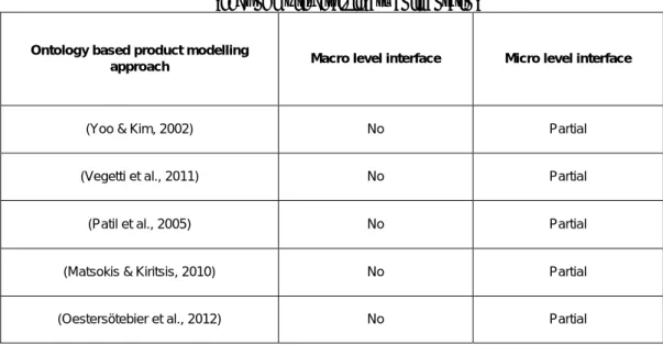
2.4 ONTOLOGY‐BASED PRODUCT MODELLING APPROACHES FOR MECHATRONIC ENGINEERING ... 60 2.4.1 Basic concept of ontology ... 60 2.4.2 Current research works on ontology‐based product modelling approaches ... 60 2.4.3 Assessment of existing ontology based product modelling approaches ... 62 2.5 SUMMARY AND ASSESSMENT OF STUDIED RESEARCH WORKS ... 63 2.5 RESEARCH APPROACHES ... 64 PROPOSITIONS ... 66 3.1 MULTI‐DISCIPLINARY INTERFACE MODEL ... 66 3.1.1 Introduction of LEGO Mindstorms used for training the basics of mechatronic engineering ... 67 3.1.2 Interface classification ... 71 3.1.3 Interface model ... 82 3.1.4 Interface compatibility rules for design of mechatronic systems ... 88 3.1.5 Synthesis of multi‐disciplinary interface model ... 92 3.2 DESIGN METHODOLOGY BASED ON MULTI‐DISCIPLINARY INTERFACE MODEL ... 93 3.2.1 General design process ... 93 3.2.2 Design phases ... 94 3.2.3 Achievement of macro level and micro level collaboration ... 105 3.3 SUMMARY ... 107 CASE STUDY ... 108 4.1 DEMONSTRATOR DEVELOPMENT ... 109 4.1.1 Introduction of 3DEXPERIENCE Platform ... 109 4.1.2 Implementation of the design methodology ... 110 4.1.3 Implementation of the multi‐disciplinary interface model ... 112 4.2 3D MEASUREMENT SYSTEM ... 117 4.2.1 System design sub‐process ... 118 4.2.2 Discipline‐specific design sub‐process ... 123 4.2.3 Synthesis of case study ... 131 4.3 SUMMARY ... 132 CONCLUSIONS AND FUTURE WORK ... 135 5.1 SUMMARY ON THE RESEARCH QUESTIONS... 135 5.2 RESEARCH CONTRIBUTIONS TO DESIGN OF MECHATRONIC SYSTEMS ... 139 5.3 FUTURE WORK ... 141 REFERENCES ... 145 LIST OF PUBLICATIONS ... 159
ABSTRACT ... 160
70
RESUME... 164
List of Figures
FIGURE 1.1HISTORICAL DEVELOPMENT OF MECHANICAL, ELECTRONIC AND MECHATRONIC SYSTEMS
(ISERMANN,2007) ... 16
FIGURE 1.2DETAILED DESCRIPTION OF MECHATRONIC SYSTEM (CRAIG &MARCHI,1996) ... 16
FIGURE 1.3MECHANICAL SYSTEMS INTEGRATING ELECTRONICS IN INTERACTION WITH INFORMATION AND POWER (SCHÖNER,2004) ... 18
FIGURE 1.4DIFFERENT INTEGRATION LEVELS IN MECHATRONIC SYSTEMS (PENAS,PLATEAUX, CHOLEY,&RIVIERE,2009) ... 21
FIGURE 1.5RELATIONSHIP BETWEEN THE RESEARCH QUESTIONS ... 32
FIGURE 2.1CONCEPTUAL PLM SYSTEM ARCHITECTURE (RACHURI ET AL.,2005) ... 35
FIGURE 2.2SYSTEMS ENGINEERING PROCESS (LEONARD,1999) ... 38
FIGURE 2.3SE DESCRIBED BY ANSI/EIA632(MARTIN,2000) ... 39
FIGURE 2.4SE DESCRIBED BY IEEE1220(DORAN,2004) ... 40
FIGURE 2.5ISO/IEC15288PROCESS MODEL (ISO/IEC15288,2002) ... 41
FIGURE 2.6SEQUENTIAL DESIGN PROCESS (ALVAREZ CABRERA ET AL.,2010) ... 44
FIGURE 2.7V-MODEL (DEPARTMENT OF TRANSPORTATION,2007) ... 46
FIGURE 2.8VDI GUIDELINE 2206(VDI2206,2003) ... 47
FIGURE 2.9DEVELOPMENT PROCESS BASED ON SE AND RFLP(KLEINER &KRAMER,2013) ... 48
FIGURE 2.10UML CLASS DIAGRAM OF THE CORE PRODUCT MODEL (FENVES ET AL.,2006) ... 57
FIGURE 2.11INTERFACE FEATURE OF EMBEDDED SYSTEM MODEL (ZHA ET AL.,2005) ... 58
FIGURE 2.12PRODUCT MODEL CLASS DIAGRAM (NOËL,ROUCOULES,&TEISSANDIER,2005) ... 59
FIGURE 2.13PROCESS MODEL DEVELOPED DURING THE IPPOP PROJECT (NOWAK ET AL.,2004) ... 60
FIGURE 3.1MECHATRONICS AND LEGO ... 71
FIGURE 3.2EXAMPLES OF LEGO TECHNIC PIECES (DIMENSIONSGUIDE,2011) ... 71
FIGURE 3.3PROGRAMMING BLOCKS OF LEGOMINDSTORM ... 72
FIGURE 3.4POWER SUPPLY OF LEGOMINDSTORM ... 72
FIGURE 3.5SENSORS OF LEGOMINDSTORM ... 73
FIGURE 3.6ACTUATORS OF LEGOMINDSTORM ... 73
FIGURE 3.7EV3 BRICK OF LEGOMINDSTORM ... 74
FIGURE 3.8EXAMPLE OF GEOMETRIC INTERFACE ... 77
FIGURE 3.9EXAMPLE OF ENERGY INTERFACE ... 78
FIGURE 3.10EXAMPLE OF CONTROL INTERFACE ... 78
FIGURE 3.11EXAMPLE OF DATA INTERFACE ... 79
FIGURE 3.12EXAMPLE OF C-I-C ... 80
FIGURE 3.13EXAMPLE OF C-I-E ... 81
FIGURE 3.14EXAMPLES OF C-I-I AND I-I-I ... 82
FIGURE 3.15EXAMPLES OF I-I-E ... 83 FIGURE 3.16EXAMPLE OF AN INTERFACE CREATING POSITIVE EFFECTS AND UNINTENDED SIDE
-EFFECTS SIMULTANEOUSLY ... 84
FIGURE 3.17UML CLASS DIAGRAM OF INTERFACE AND ITS CLASSIFICATION... 84
FIGURE 3.18THREE TYPES OF PORTS EXISTING IN THE DIFFERENT INTERFACE CONFIGURATIONS .... 86
FIGURE 3.19UML CLASS DIAGRAM OF PORT ... 89
FIGURE 3.20UML CLASS DIAGRAM OF INTERFACE ... 90
FIGURE 3.21SOLUTIONS TO SOLVE INCOMPATIBLE INTERFACES ... 95
FIGURE 3.22EXAMPLE OF SOLUTIONS TO SOLVE INCOMPATIBLE INTERFACES ... 96
FIGURE 3.23GENERAL DESIGN PROCESS: AN EXTENDED V-MODEL ... 98
FIGURE 3.24CONSISTENCY BETWEEN DIFFERENT DESIGN PHASES DURING SYSTEM DESIGN PROCESS. 102
FIGURE 3.25CONSISTENCY IN THE THREE DESIGN PHASES FOR THE LEGO ROBOT ... 104
FIGURE 3.26UML ACTIVITY DIAGRAM FOR THE DISCIPLINE-SPECIFIC DESIGN SUB-PROCESS BASED ON MULTIDISCIPLINARY INTERFACE MODEL... 108
FIGURE 3.27INSTANCE OF THE INTERFACE BETWEEN THE RECHARGEABLE BATTERY AND THE EV3 BRICK ... 109
FIGURE 4.1VPMFUNCTIONAL LOGICAL EDITOR ... 114
FIGURE 4.2COMPONENT REPRESENTATION IN 3DEXPERIENCEPLATFORM ... 117
FIGURE 4.3ENVIRONMENT REPRESENTATION IN 3DEXPERIENCEPLATFORM ... 118
FIGURE 4.4INTERFACE REPRESENTATION IN 3DEXPERIENCEPLATFORM ... 119
FIGURE 4.5REPRESENTATION OF PORT AND ITS PARAMETERS IN 3DEXPERIENCEPLATFORM .... 120
FIGURE 4.6REQUIREMENTS SPECIFICATION USING WORD,ENOVIA AND 3DEXPERIENCE PLATFORM (KLEINER,2013) ... 115
FIGURE 4.7INTERFACE COMPATIBILITY RULE AND THE TEST RESULT ... 116
FIGURE 4.8PRINCIPLE OF THE MEASUREMENT MODE:(A)ACTIVE MODE 1(B)ACTIVE MODE 2(C) PROJECTED PATTERN (D)DEFORMED PATTERN ... 122
FIGURE 4.9FUNCTIONAL AND ARCHITECTURAL MODEL FOR 3D MEASUREMENT SYSTEM ... 126
FIGURE 4.10REPRESENTATION OF PATTERN PROJECTION SUB-SYSTEM ... 127
FIGURE 4.11INTERFACE (I1.1) BETWEEN THE INDUSTRIAL ENVIRONMENT (E1) AND THE IMAGE GUIDE (C1.13) ... 128
FIGURE 4.12IMAGE GUIDE DATA SHEET ... 128
FIGURE 4.13INSTANCE OF THE INCOMPATIBLE INTERFACE I1.1 ... 129
FIGURE 4.14SOLUTION 1 DEALING WITH THE INCOMPATIBLE INTERFACE I1.1 ... 130
FIGURE 4.15INSTANCE OF THE COMPATIBLE INTERFACE I1.1 ... 130
FIGURE 4.16INTERFACE (I1.12) BETWEEN THE DMD(C1.12) AND THE IMAGE GUIDE (C1.13) ... 130
FIGURE 4.17DMD DATA SHEET AND MAXIMUM IMAGE CIRCLE DIAMETER ... 131
FIGURE 4.18INSTANCE OF THE INCOMPATIBLE INTERFACE I1.12 ... 131
FIGURE 4.19SOLUTION 2 DEALING WITH THE INCOMPATIBLE INTERFACE I1.121 ... 132
FIGURE 4.20INSTANCE OF THE COMPATIBLE INTERFACE I1.1211 ... 132
FIGURE 4.22PART OF 3D MEASUREMENT SYSTEM ... 134
LIST OF TABLES
List of Tables
Table 1.1 Main research questions and their sub-questions ... 31 Table 2.1 Details of the evaluation for design methods ... 53 Table 2.2 Assessment of the design methods regarding needs of multi-disciplinary collaboration ... 54 Table 2.3 Details of the evaluation for product models ... 61 Table 2.4 Assessment of the product models regarding needs of multi-disciplinary integration 62 Table 2.5 Assessment of the ontology based product modelling approaches regarding needs of multi-disciplinary collaboration ... 65Table 3.1 Main limitations of previous classifications ... 76
Table 3.2 Five types of interfaces ... 80 Table 3.3 Mapping between main entities of multi-disciplinary interface model and their equivalent entities in other product models ... 92 Table 4.1 Requirements, functions, components and design teams/standard component ... 125
List of Acronyms
AFIS: Association Française d'Ingénierie SystèmeAP: Application Protocol BDD: Block Definition Diagram CAD: Computer Aided Design CAx: Computer Aided x CCD: Charge-Coupled Device CPM: Core Product Model CPS: Cyber-Physical Systems CVS: Concurrent Versions System DMD: Digital Micro-mirror Device
E-CAD: Electronic/Electrical Computer Aided Design EDM: Engineering Data Management
EES: Electrical/Electronic Engineering Solutions EIA: Electronic Industries Association
EMC: ElectroMagnetic Compatibility
E-PDM: Electronic/Electrical Product Data management ESM: Embedded System Model
FBS: Function–Behaviour–State GUI: Graphical User Interface HW: Hardware
IBD: Internal Block Diagram
IGES: Initial Graphics Exchange Specification
INCOSE: International Council on Systems Engineering IoT: Internet of Things
IPPOP: Integration of Product, Process and Organisation for improvement of engineering Performance
IT: Information Technology
M-CAD: Mechanical Computer Aided Design MPD: Modular Product Development
M-PDM: Mechanical Product Data management NIST: National Institute of Standards and Technology OCL: Object Constraint Language
PCA: Printed Circuit Assemblies PDM: Product Data management PLC: Product Life Cycle
PLM: Product Lifecycle Management PPO: Product-Process-Organisation
PSRL: Product Semantic Representation Language SCM: Software Configuration Management
SE: Systems Engineering SoS: System of Systems
STEP: STandard for the Exchange of Product SW: Software
UML: Unified Modelling Language XML: Extensible Markup Language
Acknowledgement
When I am writing of the last sentence of this thesis, I realise that this piece of work is much more than my one person’s effort. Without the support and help from my thesis supervisors, my family and my friends, I would not have arrived at this point. First, I would like to give my sincere gratitude to my supervisors, Professor Benoît Eynard and Associate Professor Julien Le Duigou, for the continuous support of my PhD study and research. Their patience, motivation, immense knowledge, and their inspiring guidance during my thesis deserve the most appreciation and respect in my
heart. It is really a great experience working with them. With their abundant research experience, they show me how to become an independent researcher.
Second, I would like to thank Associate Professor Matthieu Bricogne for his help and guidance throughout the three-year research. I benefited greatly for having useful opinions and comments in weekly meetings, which greatly help me for conducting the thorough research in the field of mechatronic systems engineering.
Third, I address my acknowledgments to Professor Frédéric Lamarque, Associate Professor Laurent Petit, Associate Professor Erwan Dupont and Ph.D student Yingfan Hou for their support of the case study on the 3D measurement system. All their constructive comments and advice that have enriched my work, the different exchanges of ideas and interpretations, the time devoted to interviews and their professional experiences and knowledge in the domain of design of system mechatronic systems.
Fourth, I express thanks to the reviewers, Professor RIERA Bernard from the Université de Reims Champagne and Professor YAN Xiu-Tian from the University of Strathclyde, for agreeing to bring my work thesis. It is an honour for me to extend my thanks to the members of the jury for the time and attention they devoted to reading this work and their criticism of it.
Fifth, I would not fail to acknowledge to the Department of Mechanical Design Engineering of the Laboratory Roberval at the University de Technologie de Compiègne (UTC), where the work presented in this thesis was conducted. I would further like to give my gratitude to the financial support from the program of China Scholarships Council (CSC).
Sixth, I would like to say, I really enjoy working in the friendly atmosphere in this department. I wish to take this opportunity to express my appreciation and thanks to all the students, professors, secretaries and staff for their friendly spirit. Especially, I would like to thank all the members of I101, they are Marina Bruneau, Fabien Michelin, Christophe Danjou, Fabien Mahut, Cong Cuong Pham and Jinhua Xiao. Finally, I would like to express special thanks to my parents and my girl friend, who provide me eternal love and supports. They encourage me to explore knowledge and teach me to be a man with responsibility. With all the love and faith, I believe that tomorrow is going to be better.
THESIS STRUCTURE
Thesis structure
The topic of this thesis is on design and integration of mechatronic systems. Mechatronic system is considered as the resulting integration of electrical/electronic system, mechanical parts and information processing. Therefore to enable a systematic design process of mechatronic systems with high integration level, the so-called “multi-disciplinary integration” is required. The interest of the thesis concerns how designers can achieve such multidisciplinary integration during the design process of mechatronic systems. The structure of the thesis is organised as follows: Chapter 1 introduces the context of the research, including the concept, the historical development and the technology trends of mechatronic system. Considering the technology trends of mechatronic systems, in order to achieve a more integrated mechatronic system, the research objectives are then pointed out. However, two scientific problems - process-based problems and design data-related problems are considered as the barriers which hinder the designers to achieve the multi-disciplinary integration. According to these scientific problems, the research questions are put forward.
Chapter 2 reviews relevant literature, which sets the stage for the need of this thesis research. Considering the research objective proposed in Chapter 1, this chapter focuses on the current studies on process models and product models, which are respectively considered as the potential solutions to address the process-based problems and design data-related problems. The evaluation results of the current studies shows that the multi-disciplinary interfaces in the mechatronic systems should be further studied and developed.
Chapter 3 focuses on the propositions on multi-disciplinary interface. In this chapter the approach of multi-disciplinary interface modelling is detailed to deal with the design data-related problems. A design methodology based on the multi-disciplinary interface modelling approach is then introduced in order to solve the process-based problems.
Chapter 4 proposes a demonstrator based on 3DEXPERIENCE Platform to demonstrate the feasibility the propositions. A 3D measurement system is adopted as
a case study to show how the propositions can be applied during the design process and to validate the expected improvements.
THESIS STRUCTURE
Chapter 5 summarises the research work of the thesis. It concludes the thesis with the contributions and limitations of the propositions. The future research directions are finally pointed out.
Scientific context and research
questions
Before concentrating on the research propositions, the thesis firstly provides the context by introducing the concept, the history and the technology trends. The research objectives will be then pointed out by regarding to nowadays technology trends. However, some problems still exist in current design of mechatronic systems. Considering the problems, the research questions will be finally pointed out.
1.1 Context
1.1.1 Concept and history of mechatronics
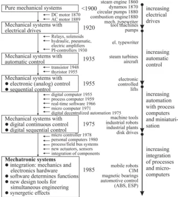
Mechanical systems have been used to generate motion, transfer forces and torque for many decades. The control systems have been gradually involved to manipulate the commanded variables of the mechanical systems (Isermann, 2007). This kind of evolution allows fulfilling much more functions compared to a pure mechanical system or pure control system. But all this could still be just called an automated system; mechatronics means more than this. Figure 1.1 summarizes the development from basic mechanical systems of the 19th century to mechatronic systems in the
1980s.
The term Mechatronics originated at the Yaskawa Corporation from the combination of mechanics and electronics in 1969. After the 1970s, the meaning of mechatronic has been broadened to include software and computation (Carryer, Ohline, & Kenny, 2011). Nowadays, mechatronics becomes the synergistic integration of mechanical parts with electrical/electronic systems and information processing (Tomizuka, 2002). Thus there are several definitions of mechatronics as a scientific discipline, but one of the most accurate definitions could be - “the synergistic integration of mechanical engineering with electronics and intelligent computer control in the design and manufacturing of industrial products and processes” (Kyura & Oho, 1996). An iconic description of such mechatronic system, multi-disciplinary design is presented in Figure. 1.2.
Figure 1.1 Historical development of mechanical, electronic and mechatronic systems (Isermann, 2007)
Figure 1.2 Detailed description of mechatronic system (Craig & Marchi, 1996)
With the development of technology, other disciplines (e.g. optics, hydraulics, pneumatics, etc.) are involved in the development of mechatronic systems
(Gausemeier, Frank, Donoth, & Kahl, 2009). The application domain of mechatronic systems have been accordingly enlarged, which leads to modern smart products. By now the concept and the historical development of mechatronic system have been introduced. This historical development indicates that the mechatronic systems become more and more integrated. According to the definition proposed by (Kyura & Oho, 1996), the design of mechatronic systems should focus not only on the synergistic integration for the products, but also on the integration of the several involved disciplines during the design processes. Therefore much more attention should be paid to such two kinds of integration in the future. The development trends of mechatronics engineering related to the product and the process will be introduced in next sub-sections.
1.1.2 Development trends of mechatronics engineering
The above sub-section introduces the basic concept of mechatronic systems and its development history, which reveals the two kinds of integration relevant to the design of mechatronic systems-integration related to the product and the process. This sub-section will present the development trends of mechatronics engineering from the two types of integration. Considering the technology trends of mechatronic systems, the research objectives are then pointed out.
1.1.2.1 Integration related to the product
The previous discussion indicates that the mechatronic systems become more and more integrated. The integration related to the product will be introduced in this sub-section. According to Bricogne, the integration related to the product can be divided into functional integration and physical integration (Bricogne, 2015).
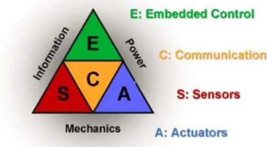
With the development of technology, more and more functionalities have been integrated into mechatronic systems. Figure 1.3 from (Schöner, 2004) presents such evolution, the different involved engineering disciplines and the overlaps between them. First, Actuators (A), represented on the right angle of the triangle, are added. They are in charge of managing actuation forces and speed. It can be regarded as the first combination of electronic and mechanical disciplines. To supply power to these actuators, external power is needed and generally provided by electrical engineering disciplines. The integration related to the product of mechatronic systems allows fulfilling more functions in more compact systems compared to a pure mechanical system or pure electronic system. “But all this could still be just called an automated
system; mechatronics means more than this” (Schöner, 2004). Mechatronic systems are the resulting product of a global concurrent engineering or integrated design process (Sohlenius, 1992; Tichkiewitch, 1994). This aspect will be detailed in the section, relative to process integration. Second, the Embedded control (E), comes “with the goal of an automatic or more reproducible process” (Schöner, 2004). On the top angle of the triangle, embedded systems, considered as the overlap between the electronic and software disciplines, have been gradually included in modern mechatronic systems for information processing (Marwedel, 2011). Third, the Sensors (S), on the left angle, allow the system to get detailed information about the status of the system and to fulfil correctly its functions to the various environmental conditions. It is considered as the overlap between the mechanical and IT disciplines. Finally, the Communication (C) is now considered as the central part of the system, especially for distributed systems.
It allows integrating the sub-system into the whole product/system.
Figure 1.3 Mechanical systems integrating electronics in interaction with information and power (Schöner, 2004)
Led by the development of several technologies, mechatronic systems are influenced by some new development trends. For instance, with the support of information processing and cyber technologies, the information and communication are much more closely integrated into mechatronic systems. During the 1990s, this trend shifted towards information processing being associated with personal computers processing (Marwedel, 2011). The convergence of information resources has happened and the entire physical world itself is gradually becoming a type of information system in the real time (Parwekar, 2011). Nowadays we are experiencing the fourth industrial revolution named information revolution (Hermann, Pentek, & Otto, 2015). In this context, the term Industry 4.0 was manifested for the first time at the
Hannover Fair with the presentation of “Industry 4.0” initiative (Jazdi, 2014). Based on the information and communication technologies, various types of systems, such as embedded systems, Cyber-Physical Systems (CPS), Internet of Things (IoT),
System of Systems (SoS) etc., have attracted the attention from both academia and industry. By making use of the above systems, Industry 4.0 provides a scenario in which human can monitor physical processes, create a virtual copy of the physical world and make decision.
The embedded system, as introduced before, can then be considered as the link between the cyber world and the physical systems. However, the strong link to physics has been stressed even more by introducing the term “Cyber-Physical Systems”. CPS are defined as “integrations of computation and physical processes” (Lee, 2008). CPS begins to focus on the integration of knowledge and engineering principles across the computational and engineering disciplines (network, control, software, human interaction, learning theory, as well as electrical, mechanical, chemical, biomedical, material science, and other engineering disciplines) to develop new CPS science and supporting technology (Baheti & Gill, 2011).
Another concept influencing mechatronic field is Internet of Things, which is quite similar to CPS. Firstly proposed by Kevin Ashton in a presentation in 1998 (Weber & Weber, 2010), IoT is defined as “a world where physical objects are seamlessly integrated into the information network, and where the physical objects can become active participants in business processes. Services are available to interact with these ‘smart objects’ over the Internet, query their state and any information associated with them, taking into account security and privacy issues” (Haller, Karnouskos, & Schroth, 2009). Over the IoT, CPS communicate and cooperate with each other and humans in real time (Hermann et al., 2015). However, the frontier between CPS and IoT has not been clearly identified since both concepts have been driven in parallel from two independent communities, although they have always been closely related (Koubaa & Andersson, 2009). CPS can be considered as an opportunity and a backbone to promote IoT concept and associated technologies. They are really closed to mechatronic systems, even if the focus is more on the software parts of the system, whereas mechatronic systems are traditionally more focused on the hardware parts of the system (Bricogne, 2015).
One example of research towards the implementation of IoT is the field of
“Intelligent product” (Hribernik, Ghrairi, Hans, & Thoben, 2011). (McFarlane, Sarma, Chirn, Wong, & Ashton, 2003) defines the intelligent product as “a physical and information based representation of an item which possesses a unique identification”. It is able to communicate efficiently with its environment, can collect and/or store data about itself, deploys a language to display its requirements, features and etc. It is capable of contributing to or making decisions relevant to its own destiny.
Mechatronic system can then be considered as a platform supporting the development of IoT/Intelligent product.
The above introduction of CPS and IoT indicates that there has been a growing interest in a class of systems, rather than a single complex system. Such class of systems is sometimes called Federation of Systems (FoS) or System of Systems (SoS) (Jamshidi, 2009). Like CPS, System of Systems (SoS) can also represent the new vistas for various applications, such as aerospace, manufacturing, military and so on (Samad & Parisini, 2011). (Carlock & Fenton, 2001) define SoS as “large-scale concurrent and distributed systems that are comprised of complex systems”. The principal differences between a thing being either a “system” (e.g., a mechatronic system) or a SoS are on the nature of a system’s composition (Boardman, 2006). The multi-disciplinary nature of SoS also requires close collaboration among several disciplines (Samad & Parisini, 2011). In summary, there is a tendency towards mechatronic systems which are envisioned as building blocks for the design of system of systems.
Above discussion indicates that more and more innovative functionalities have been integrated into mechatronic systems. For example, the integration of cyber technology that makes the products Internet-enabled improves innovative services to achieve, among other things, Internet-based diagnostics, maintenance, operation, etc. in a cost-effective and efficient manner (Jazdi, 2014). As a result, from the simple automated systems in which mechanical and electronic components are combined together, through the modern smart products in which various disciplines have been involved, to CPS, IoT and SoS into which cyber world has been integrated, new functionalities have been provided and become much more integrated than before thanks to the development of technology.
Besides the functional integration discussed previously, the physical level of mechatronic systems has become increasingly integrated as well. Several levels of physical integration of mechatronic systems related to product exist (Figure
1.4). The first kind of integration is called “separated components”. In this case, components are designed separately and are just incorporated in the same system thanks to cable. The second level of integration corresponds to the concept of “joined components”. The mechanical parts will be designed in order to place the electrical and/or the electronic parts in juxtaposition with each other. Distances between components have been reduced. The third kind of integration is called “included”: electronic components are spread out into the whole system, but this kind of integration does not achieve a “real” integration. Finally, the ultimate integration level is the “merged” components: electronics is integrated as close as possible to the
mechanical and electrical components. Parts are gathered in a consistent and functional manner and mechanical parts can also be used as signal transmitter. The contributions of this integration are various:
• Physical integration: spatial and weight optimisations,
• Functional integration: detection, communication, control/information processing allow the system to provide new functionalities and to be more reliable.
Figure 1.4 Different integration levels in mechatronic systems (Penas, Plateaux, Choley, & Rivière, 2009)
The development trends, as presented before, related to mechatronic systems show that the design of mechatronic systems has to integrate various disciplines. This complexity is linked to the increasing integration level and the wider range of collaborators involved. However, such integrated design is often hampered by lack of uniform interpretation of product modelling languages and terminologies, leading to rework when discrepancies are discovered (Bock, Zha, Suh, & Lee, 2010). Designers geographically and organizationally distributed in global economy worsen these problems (Shen & Barthès, 2008).
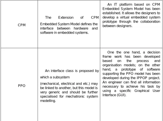
Product modelling yields product data models drawn from a wide variety of source as its results. A product model database which is generated by product modelling approach during the product development process should be able to support all the concerns of the whole product life cycle. Here the term product development process refers to those stages or phases from an initial concept to a proven prototype of the product (Krause et al., 1993). Therefore the product model can be also considered as an effective support for the design of mechatronic systems. Previous work in product modelling approach can be generally divided into two parts, model-based product (or product model in the thesis) and ontological techniques (Bock et al., 2010). Product models have been used much longer than ontological techniques and numerous product models have been developed, such as ISO 10303 (STEP, STandard for the Exchange of Product model data) (ISO 10303, 1994), the National Institute of Standards and Technology (NIST) Core Product Model (CPM) and its extensions
(Fenves, Foufou, Bock, & Sriram, 2006), and Product-ProcessOrganisation model (PPO) (Noël & Roucoules, 2008). They provide engineering-oriented language and the meaning of the language is not strictly specified. Therefore the product models define a syntactic data representation (Abdul-ghafour, Ghodous, & Shariat, 2012). Ontology is initially proposed as an important and natural means of representing real world things, or things intended for the real world (GómezPérez, Fernandez-Lopez, & Corcho, 2004). It has been recently applied to product modelling. Compared with product model, ontology defines a semantic data representation (Abdul-ghafour et al., 2012). It can give cleaner meaning to product models by interpreting them as physical things, rather than linguistic constructions such as modelling languages used by product models. Unlike the product model, the ontology is not tied to modelling languages for ease of use in the engineering community. Therefore the designers should give ontological meaning by making use of ontology languages for individual, physical objects or occurrences of behaviour when using it for product modelling (Bock et al., 2010). Efforts that combine ontology and modelling languages of product model have been made by current studies (Chungoora et al., 2013; Gil & Martin-Bautista, 2012; Sun, Fan, Shen, & Xiao, 2012).
The above introduction of the two product modelling approaches - product model and ontology introduces that both of them can be used as an effective support for the integration related to the product during the design of mechatronic systems, because they propose a natural means to help the designers to access, store, serve and reuse the design-related data during the design process. And meanwhile, the possibility of creating a standard representation of the design-related data which can be understood by the designers of different disciplines is also indicated by the nature of product model and ontology.
In this section, the integration related to the product has been presented as a great challenge for the design of mechatronic systems. Product modelling approach has been also introduced and is considered in this thesis as an effective support to the integration related to the product. However, in order to achieve the multi-discipline based integrated design of mechatronic systems, the design process has to be called for the coordination of the design teams of different disciplines. In other words, the collaboration among different expertise and disciplines during the design process of mechatronic system plays a key role to ensure that the results of their efforts are successful, especially to obtain an integrated system. Therefore, the second type of integration which has been discussed in next sub-section is related to the design process.
1.1.2.2 Integration related to the process
The integration related to the process requires a high level collaboration from both the designers and the various involved disciplines during the design process. The design of mechatronic systems calls for multi-disciplinary collaboration, the designers of which cannot master all the knowledge needed for the design, and sometimes the designers are separated in different areas and even different countries. That is the reason why collaborative and concurrent approaches for the design of mechatronic systems are so complex and so challenging. Such challenges will generally lead to a poor integration level. From the traditional sequential design (Pahl, Beitz, Feldhusen, & Grote, 2007) to the concurrent engineering (Li, Zhang, & Chen, 2001) numerous design methodologies have been proposed to organise the design process in order to achieve a high level multi-disciplinary integration during the design process of mechatronic systems. The historical development of mechatronic systems discussed in Section 1.1.1 indicates that the mechatronic systems become more and more integrated thanks to the convergence of technological diversity of from different disciplines. To keep up with such development trends of mechatronic systems, some new development methodologies have been proposed and are still under the study of academia and industry.
Agile development methods 1 were seen initially as software engineering methods in
which requirements and solutions evolve through collaboration between self-organising, cross-functional teams (Highsmith, 2002). They were initially viewed as best suited to small and non-critical projects with co-located teams (Abrahamsson, Conboy, & Wang, 2009). Therefore how to apply the agile development methods to the design of mechatronic systems is still a great challenge for the designers (Bricogne, 2015). On the one hand, the design of mechatronic systems is often considered as a large-scale project and the designers are often separated in different areas. On the other hand, the design process of mechatronic systems always requires a regulated environment in which the design process is expressed and adapted by careful tailoring. The constraints of current agile development methods about small projects and colocated teams have been addressed by several research studies on agile adoption by large teams (Cao, Mohan, Xu, & Ramesh, 2004; Kahkonen, 2004) and in distributed environment (Boland & Fitzgerald, 2004; Kircher, Jain, Corsaro, & Levine, 2001). However, the regulated environments required by the design of
mechatronic systems and the agile development methods are often seen as fundamentally incompatible. How an agile approach can be implemented successfully in a regulated environment is still under discussion (Cawley, Wang, & Richardson, 2010; Fitzgerald, Stol, O’Sullivan, & O’Brien, 2013).
Specific methods have been proposed according to the principles of agile development. How to use them during the design process of mechatronic systems have attracted more and more attention and research. Scrum, one specific method of agile development, is originally suggested for “managing product development project” and mainly used for software development projects (Boehm, 2002). However, Scrum has been extended and some examples in literature show that design methods based on Scrum have been provided to solve the multi-disciplinary problems existing in the design of mechatronic systems (Cooke, Maarten Bonnema, & Poelman, 2012; Grimheden, 2013; Stelzmann, 2011).
Increasing the integration of mechatronic systems and decreasing time for development and cost reduction require a lean development process. Lean development is rooted in the Toyota Production System from the 1950s (Womack, Jones, & Roos, 2007). The core ideas of lean development method are to eliminate waste, achieve quality first time, and focus on problem solving (Poppendieck & Poppendieck, 2003). Studies have been carried on to apply the lean development during the design process of mechatronic systems (Elezi,
Graebsch, Hellenbrand, & Lindemann, 2011; Hellenbrand & Lindemann, 2011; Jönsson, 2004).
The development trends of design processes for mechatronic systems proposed by the design methodologies discussed previously imply that the designers have been moving increasingly closer to the users (or customers) of their products. In other words, not only the collaboration of designers from different disciplines during the design process become more and more integrated, but the involvement of users (or customers) during the design process is becoming more and more important as well. The terms Co-design is proposed to describe such participatory design. Co-design, in a broader sense, refers to the creativity of designers and people not trained in design working together in the design development process (Sanders & Stappers, 2008). Various tools and methods of co-design have been proposed, such as Crowdsourcing, which is the act of taking a task traditionally performed by a designated agent and outsourcing it by making an open call to an undefined but large group of people (Howe, 2008), and Personas, which provide task scenarios describing how the users interact with the design (Long, 2009). Generally speaking, in co-design, the
boundaries of the roles are blurred. The user is granted the position of expert of his/her experience, and plays a large role in knowledge development, idea generation and concept development (Hribernik et al., 2011).
As discussed before, in order to achieve a high-level integration related to the process, the designers should focus on both the “coordination and the synchronisation of the different disciplines, specific development processes, activities, tasks and results across all fields” (Abramovici & Bellalouna, 2007) and “complex coherences and interactions between the disciplines” (Abramovici & Bellalouna, 2007). Furthermore, according to (Abramovici & Bellalouna, 2007), attention should be paid to “the comprehensive integration, configuration, change and release management across all disciplines”. The two previous sub-sections present the two types of multi-disciplinary integration during the design of mechatronic systems. The first type concerns the integration related to the product of mechatronic systems. This integration allows fulfilling more functions in more compact systems compared to a pure mechanical system or pure electronic system. The second type focuses on the integration related to the process. A well-organised collaborative and concurrent design of mechatronic system is required during the design process. By analysing the development trends of mechatronic systems, the scientific problems and the research objectives will be pointed out in next sub-section.
1.2 Scientific problems and research
objectives
1.2.1 Scientific problems
As depicted previously, in order to achieve the multi-disciplinary integration for the design of mechatronic systems, attention should be paid to the two types of integration: a design process with high-level multi-disciplinary collaboration and a mechatronic system with high-level functional and physical integration. The former raises “Process-based problems” while the latter brings up “Design data-related problems” (Abramovici & Bellalouna, 2007). According to (Abramovici & Bellalouna, 2007), “Process-based problems” are linked to the fact that the coordination and the synchronisation of the “different disciplines, specific development processes, activities, tasks and results across all fields is not sufficiently supported”, but also to the fact that complex “coherences and interactions between the
disciplines are considered in a late development phase”. Furthermore, “comprehensive integration, configuration, change and release management across all disciplines is little or barely supported” (Abramovici & Bellalouna, 2007).
The second kind of difficulties encountered during design of mechatronic systems, called “Design data-related problems” (Abramovici & Bellalouna, 2007), is related to the edition and management tools heterogeneity. For example, mechanical designers use Computer Aided x (CAx) applications to support the product development process. The data generated are generally stored in Mechanical Product Data Management (M-PDM) systems while electrical and electronic designers use Electrical/Electronic Engineering
Solutions (EES) to create data which are stored in Electronic/Electrical PDM (E-PDM). Software designers use development solutions to create source code that is managed thanks to Software Configuration Management (SCM) or Concurrent Versions System (CVS) systems. This heterogeneity in terms of product data, data models and data formats leads to several problems that can be summarised as no adequate multi-disciplinary integration of product data (Bricogne et al., 2010). However, neither academia nor industry has yet provided explicit solutions to solve such two kinds of problems. Considering the two kinds of problems existing in the design of mechatronic systems, the research objectives will be presented in next sub-section.
1.2.2 Research objectives
The two kinds of scientific problems related to the multi-disciplinary design of mechatronic systems discussed before reveal our research objectives in this sub-section. They can be divided into two parts.
The first research objective is relevant to the design data-related problems. As discussed before, both the functionality and the physical size of mechatronic systems become increasingly integrated and compact respectively and different disciplines have been gradually integrated into the design of mechatronic systems. However, due to the heterogeneous design data coming from different disciplines during the design process, lack of uniform interpretation of designrelated data often hamper such integrated design. Engineers distributed geographically and organizationally in global economies worsen these problems (Shen & Barthès, 2008). As a result, the first research objective is to provide a standard representation to link the design-related data created by different discipline during the design process. In other words, a
standard representation for the “interfaces” in mechatronic systems should be proposed. Such interfaces exist not only between sub-systems (or between sub-system and environment) designed by different disciplines, but also among the engineers who collaborate or coordinate by sharing information through formal or informal interaction. In order to achieve this objective, current product modelling approach should be further developed according to the mechatronic systems specificities. The second research objective is relevant to the process-based problems. A new design method which can realise a better coordination and synchronisation of the different disciplines and the engineers during the design processes should be achieved. To be more precise, this new design method should not only describe the generic procedure for the design of mechatronic systems from the identification of all requirements on the total system to a uservalidated system, but also support each design phase where individual engineers can proceed and react in unforeseen situations and structure design sub-tasks.
In order to achieve the research objectives, the research questions will be pointed out in next sub-section.
1.3
Research questions
As discussed before, in order to achieve a higher degree of multi-disciplinary integration for the design of mechatronic systems, the designers should focus not only on the synergistic integration for the products (i.e. integration related to the product), but also on the integration of the different involved disciplines during the design processes (i.e. integration related to the process). Therefore the main research questions addressed in this thesis are:
• Research questions related to the design process: How to achieve a multi-disciplinary and holistic process for the design of mechatronic systems? • Research questions related to the design data: How to manage data issued
from several discipline to support the multi-disciplinary integration during the design process of mechatronic system?
A series of sub-questions are listed below for each of the main research questions. 1.3.1 Research questions related to the design process
Two research sub-questions of design process can be identified hereafter:
How to support the macro level collaboration?
As mentioned by (Shetty & Kolk, 2010), mechatronic systems are often built from discipline homogeneous subsystems (mechanics, electrics/electronics and software). Concurrent engineering is a work methodology based on the parallelisation of design tasks carried out by different design teams (Sohlenius, 1992). It is of great importance as the design cost and development lead-time can be drastically reduced through the design tasks carried out at the same time (Wang, Shen, Xie, Neelamkavil, & Pardasani, 2002). Such concurrent engineering for the design of mechatronic system is carried on in a concurrent manner with a special focus on the subsystems and the interfaces among them (Wikander, Törngren, & Hanson, 2001). The macro level collaboration emphasises such discipline homogeneous collaboration from different design teams. It not only focuses on the assembly of the subsystems from different specific design disciplines, but pays special attention to the interfaces among them as well.
How to support the micro level collaboration
The design process of mechatronic system should also focus on the collaboration of the different designers, such as communication among designers, data sharing and exchange, etc. How to achieve the coordination of resources and designers has attracted increasing attention(Girard & Doumeingts, 2004).
The collaboration among the individuals is called in the thesis micro level collaboration. Traditionally, the micro level collaboration is often performed thanks to informal exchanges supported by e-mail, phone or regular meeting. In extreme collaboration, designers work physically together, i.e., at the same place, as long as they have to finish the task. Such traditional low-tech tools, like face-to-face discussion, whiteboards and flip charts, facilitate daily communication in several ways. On the one hand, designers can break out and start an instantaneous meeting as soon as a planned or unplanned issue arises. On the other hand, designers can become involved to prevent others from making uninformed decisions or immediately adapt their work to incorporate an unexpected result (Garcia, Kunz, Ekstrom, & Kiviniemi, 2004).
However, as discussed above, mechatronic systems have become more and more complex and integrated, and the designers are often geographically distributed. Therefore the low-tech collaboration tools such as face-to-face discussion are impossible for designers’ daily communications. With the support of information technology, the tools and applications including graphical modelling, numerical simulations and analyses, networked support and standard product models, the
collaboration among the designers, which provides an instantaneous information sharing, can be consequently achieved. Product Data Management (PDM) systems, one example of integration tool connecting many different areas of product development, manage productrelated information such as geometry, engineering drawings, project plans, product specifications, analysis results, bills of material, engineering change orders and many more (Eynard, Gallet, Nowak, & Roucoules, 2004; Xu & Liu, 2003). PDM can ensure that the right information is available to the right person at the right time and in the right form throughout the enterprise and many commercial PDM systems have been developed in recent years, such as
ENOVIA2 belonging to Dassault Systèmes, Teamcenter3 belonging to Siemens,
Windchill4 belonging to PTC and so on. But the detailed modelling method and the
framework of those commercial PDM systems are seldom reported (H. Tang, Guo, Huang, Li, & Li, 2015).
1.3.2 Research questions related to the design data
Section 1.2.1 presents the challenges relevant to the design data-related problems. By analysing these challenges, two research sub-questions of design data can be identified:
How to describe the macro-level interface?
During the design process of mechatronic system, a great number of subsystems are developed by discipline-specific design teams. With the purpose of two subsystems (or components) defined by different design teams to be interconnected, there must be compatible interfaces in mechanical, electronic/electrical and software disciplines (Thramboulidis, 2005), which are called in this thesis macro level interfaces. Such interfaces describe the associations between subsystems, both to indicate how subsystems should be joined in the final product and provide high-level guidance for the disciplinespecific design teams (Bettig & Gershenson, 2010). The macro level interfaces can help the design teams to achieve the basics for integration of the subsystems. By comparing the description of macro level interface with that of macro level collaboration described previously, macro level interface envisions to be an
2 http://www.3ds.com/products-services/enovia/ 3 http://www.plm.automation.siemens.com/
effective support for macro level collaboration during the design process of mechatronic design.
How to describe the micro-level interface?
The engineers need another kind of interface which allows them to exchange and share information or data during the design process of mechatronic system.
It intends to help designers to collaborate or coordinate by sharing information
through formal or informal interaction (Zha & Du, 2006). Such kind of interface, called micro level interface in this thesis, notifies the designers that their discipline-specific solutions have to be taken into account by other disciplines for their own solutions to manage conflicts between them. Because micro level interface has been built with a lot of information and included in many distributed computer systems to support the design process of mechatronic system, it fosters a better micro level collaboration. In summary, micro level interface can help engineers to have a well-organised concurrent engineering for the design process of mechatronic system, focusing on possible inconsistencies or poor integration.
1.3.3 Relationship between the two main research questions
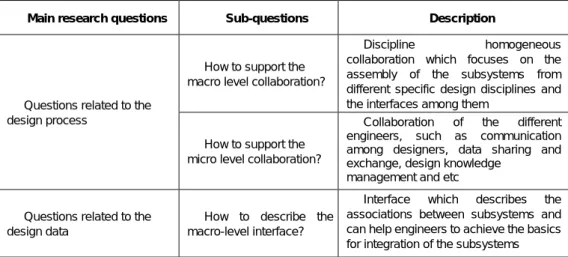
The sub-questions of the two main research questions have been presented before. Table 1.1 shows the summary of the two main research questions and their sub-questions.
Table 1.1 Main research questions and their sub-questions
Main research questions Sub-questions Description
Questions related to the design process
How to support the macro level collaboration?
Discipline homogeneous collaboration which focuses on the
assembly of the subsystems from different specific design disciplines and the interfaces among them
How to support the micro level collaboration?
Collaboration of the different engineers, such as communication among designers, data sharing and exchange, design knowledge
management and etc Questions related to the
design data
How to describe the macro-level interface?
Interface which describes the associations between subsystems and can help engineers to achieve the basics for integration of the subsystems
How to describe the micro-level interface?
Interface which allows engineers to exchange and share information or data from other disciplines and helps designers collaborate or coordinate through formal or informal interaction
In summary, design information can be classified into two categories: design process information and product information (Zha & Du, 2006). Macro level interface and micro level interface are considered as effective supports for macro level collaboration and micro level collaboration separately. Figure 1.5shows the relationship between the sub-questions of macro-level collaboration and macro-level interface and micro-level collaboration and micro-micro-level interface.
Figure 1.5 Relationship between the research questions
In order to position the research proposition relatively to current design methods and product models, next chapter will describe the state of the art followed by the research propositions.
State of the art
This chapter reviews current research works of mechatronics design. As above discussed, in order to achieve the multi-disciplinary design and integration of mechatronic systems, the design method and the product model are considered as the potential solutions to the main research questions presented in Chapter 1. In this chapter, two approaches, Product Lifecycle Management (PLM) and Systems Engineering (SE), are first reviewed. On the one hand, many design methods are considered as methodologies and supports of SE. On the other hand, various product models have been proposed to support Product Data Management (PDM) functions of PLM during the design process of mechatronic systems. Then, current research works on design methods and product models enabling mechatronic design and disciplinary integration in mechatronics are therefore presented. By analysing the evaluation results of design methods and product models, the research approaches will be introduced at the end of this chapter.
2.1 Product design
In this section, two approaches dealing with multi-disciplinary collaborative design of product with high level integration are presented. The first approach is Product Lifecycle Management (PLM). It covers all activities performed along the product lifecycle (Terzi, Bouras, Dutta, Garetti, & Kiritsis, 2010). Various product models supporting PDM functions of PLM during the design process of mechatronic systems have been proposed. The second approach is System Engineering (SE), which focuses on the design and management of complex engineering systems over their life cycles (Blanchard, 2008). Based on the general systems engineering process, many design methods have been proposed. As a result, before reviewing the current studies on product models and design methods, we will firstly go over these two approaches.
2.1.1 Product Lifecycle Management
2.1.1.1 Definition of PLM
The concept of the Product Life Cycle (PLC) has been introduced since the 1950s in order to describe every phase of a product goes through, from the first initial requirement until it is retired (Stark, 2011). In the early 1980s, the Computer Aided Design (CAD) systems have appeared. Then the Engineering Data Management (EDM) and the Product Data Management (PDM) emerged in the late1980s because the need to keep track of the increasing number of design data generated by CAD systems was recognised by the engineers in the manufacturing industries (Saaksvuori & Immonen, 2002). In order to fill the gap between the PDM and the enterprise business activities, during the 1990s, the concept of Product Lifecycle Management (PLM) was proposed. Different from the PDM system that mainly focuses on managing the product data, the PLM solution focuses on managing all the product-related knowledge throughout the different phases of the PLC (Ameri & Dutta, 2005). As defined by (Saaksvuori & Immonen, 2002), PLM is a “systematic, controlled concept for managing and developing products and related information”. It ensures “the management and the control of product process (product development, production and product marketing)” and provides “the order-delivery process, the control of product related information throughout the product life cycle, from the initial idea to the scrap yard” (Saaksvuori & Immonen, 2002).
2.1.1.2 PLM and PDM systems
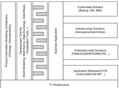
PLM systems are tools that assist a company in the implementation of PLM concept (Rachuri, Fenves, Sriram, & Wang, 2005). The full PLM system functionality can be achieved by the specific components shown in Figure 2.1. These are: (1) an Information Technology (IT) Infrastructure; (2) a Product Information Modelling Architecture; (3) a Development Toolkit and Environment; and (4) a set of Business Applications. The IT infrastructure is the foundation that includes hardware, software, and Internet technologies, underlying representation and computing languages, and distributed objects and components. PLM systems form the top of the corporate software hierarchy and frequently implemented so that they depend on subsidiary systems for detailed information capture and dissemination (Rachuri et al., 2005). Design of complex products, such as mechatronic systems, often requires the teams of designers from several disciplines and geographical distributed locations to work
together. The PDM functions of PLM are often used as an effective support enabling the collaboration during the design process of complex products. On the one hand, PDM is considered as a category of software that aims to store product data into a database. The information mentioned here includes CAD models, drawings and their associated documents (Eynard et al., 2004). On the other hand, PDM can also be considered as an integration tool connecting many different areas of product design, which ensures that the right information is available to the right person at the right time and in the right form throughout the enterprise (Xu & Liu, 2003).
Figure 2.1 Conceptual PLM system architecture (Rachuri et al., 2005)
A typical PDM system possesses a basic set of functions and features. These may include a database, sets of user-directed functions and sets of utility functions. The database is considered as the foundation of a PDM system, so all kinds of product information can be stored in this database. In general, two types of data are stored in the data vault: the product data generated from various applications and the meta-data, which contains data about the PDM controlled information (Xu & Liu, 2003).
2.1.1.3 Benefits of PLM systems for the design of mechatronic systems
Generally speaking, PLM systems can help the designers to achieve multiple advantages in terms of collaboration. The benefits for the design of mechatronic systems can be summarised as follows:
• Achieve the multi-disciplinary collaboration: during the early design phase of mechatronic systems, the PDM functions of a PLM system can help the designers from different disciplines to collaborate and identify the new
product and others currently in production. In other words, the PLM systems can lead to a collaborative development process of new product as well as improvements on existing products (Miller, 1998).
• Reduce the complexity of accessing the information: the PLM systems can simplify many day-to-day user operations by managing and automating routine tasks, such as searching for drawings, tracking approvals, and completing status reports (Liu & Xu, 2001). This improvement will greatly reduce the complexity of accessing the information during the design process of mechatronic systems.
• Reduce the lead-time and the cost for the design of mechatronic systems: because of the increasing complexity of information during the design process of mechatronic systems, the lead-time and the cost can be increased dramatically. The PLM systems help the designers to access, store, serve and reuse the information more effectively and efficiently, so the lead-time and the cost for the design of mechatronic systems can be greatly reduced (X. Tang & Yun, 2008).
• The design process of mechatronic systems indicates that a global control of the business process through all its lifecycle should be taken into consideration. In such multi-disciplinary context, how to manage the different evolutions of components in mechatronic systems becomes one of the main difficulties. In order to overcome this difficulty, it is necessary to keep the coherence and the information integrity as well as to allow a real collaboration between the different designers throughout the life cycle of the product. PLM systems seem the most appropriate support to help the designers to achieve this objective (Abid, Pernelle, Noterman, Campagne, & Amar, 2014). The first approach of product design - Product Lifecycle Management (PLM) has been presented in this section. PLM can help the designers achieve the collaborative design process of products because it covers all activities performed along the product lifecycle. The product model can be used as an effective support to the PDM function, one of the most important elements in the implementation of PLM. However, a product model implemented in the PDM function of PLM systems which can support the multi-discipline based integrated design of mechatronic system has not been fully developed (Zheng, Bricogne, Le Duigou, & Eynard, 2014a).
In this section the first approach dealing with multi-disciplinary collaborative design of product has been gone over. The product model implemented in the PDM function
of PLM systems seems to be a potential solution to the design data-related problems. Existing product models will be then surveyed in Section 2.2.2. Next section presents the second approach of products design by focusing on SE. Many design methods have been proposed based on the general system engineering process, which are all considered as the potential solutions to solve the process-based problems.
2.1.2 Systems Engineering
2.1.2.1 Definition of systems engineering
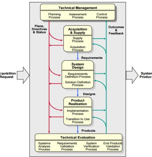
According to different background and personal experiences of engineers, SE may be defined in a numbers of ways. However, there is a common theme that deals with a top-down process, which is lifecycle oriented, involving the integration of functions, activities and organisations (Blanchard, 2008). The International Council on Systems Engineering (INCOSE) defines systems engineering as “Systems engineering is an interdisciplinary approach and means to enable the realisation of successful systems” (INCOSE, 2015). It focuses on “defining customer needs and required functionality early in the development cycle, documenting requirements, and then proceeding with design synthesis and system validation while considering the complete problem”. As shown by Figure 2.2, the fundamental SE activities are Requirements Analysis, Functional Analysis and Allocation, and Design
Synthesis - all balanced by techniques and tools collectively (Leonard, 1999). SE considers both the business and technical needs of all customers with the goal of providing a quality product that meets the user needs.
Generally speaking, SE describes a view of all the processes that have to be performed in order to engineer and develop a complex system, considering its complete lifecycle (Lardeur, 2006). Some international standards have been developed to describe the systems engineering process.
2.1.2.2 ANSI/EIA 632
The ANSI/EIA 632 was developed by the G47 Systems Engineering
Committee of the Electronic Industries Association (EIA) and titled “Systems Engineering” in August 1998 and the full standard was expanded in scope to include all the technical processes for engineering a system (Martin, 1998). It is intended to be a higher level abstraction of the activities and tasks found in the intermediate standard version plus those other technical activities and tasks deemed to be essential to the engineering of a system (Martin, 1998). The focus of this standard is on conceptualizing, creating and realizing a system and the products that make up a system. Figure 2.3 shows the thirteen processes directly related to the technical aspects of engineering systems. It defines representative tasks and the expected outcomes associated with each one. There is not one process but a series of processes, in groups, with loops among them (Martin, 2000).
Figure 2.3 SE described by ANSI/EIA632 (Martin, 2000)
2.1.2.3 IEEE 1220
The second standard reviewed here is IEEE 1220, entitled “Application and Management of the Systems Engineering”. It provides the next-level-of-detail description of the systems engineering processes defined in EIA 632. Figure 2.4 outlines the systems engineering process proposed by IEEE 1220. It generally includes six processes as follows: Requirements Analysis, Requirements Validation, Functional Analysis, Functional Verification,
Synthesis and Physical Verification. These processes are linked together via
Control Processes consisting of Data Management; Configuration Management; Interface Management; Risk Management and Performancebased Progress Measurements (Doran, 2004).