RESEARCH OUTPUTS / RÉSULTATS DE RECHERCHE
Author(s) - Auteur(s) :
Publication date - Date de publication :
Permanent link - Permalien :
Rights / License - Licence de droit d’auteur :
Bibliothèque Universitaire Moretus Plantin
Institutional Repository - Research Portal
Dépôt Institutionnel - Portail de la Recherche
researchportal.unamur.be
University of Namur
Towards Cyber-Security Protection of Critical Infrastructures by Generating Security
Policy for SCADA System
Feltus, Christophe; Ouedraogo, Moussa; Khadraoui, Djamel
DOI:
10.1109/ICT-DM.2014.6917782
Publication date:
2014
Document Version
Première version, également connu sous le nom de pré-print Link to publication
Citation for pulished version (HARVARD):
Feltus, C, Ouedraogo, M & Khadraoui, D 2014, 'Towards Cyber-Security Protection of Critical Infrastructures by Generating Security Policy for SCADA System', Papier présenté à The 1st International Conference on
Information and Communication Technologies for Disaster Management (ICTDM'2014), Algérie, 24/03/14 -25/03/14. https://doi.org/10.1109/ICT-DM.2014.6917782
General rights
Copyright and moral rights for the publications made accessible in the public portal are retained by the authors and/or other copyright owners and it is a condition of accessing publications that users recognise and abide by the legal requirements associated with these rights. • Users may download and print one copy of any publication from the public portal for the purpose of private study or research. • You may not further distribute the material or use it for any profit-making activity or commercial gain
• You may freely distribute the URL identifying the publication in the public portal ?
Take down policy
If you believe that this document breaches copyright please contact us providing details, and we will remove access to the work immediately and investigate your claim.
Towards Cyber-Security Protection of Critical
Infrastructures by Generating Security Policy for
SCADA Systems
Christophe Feltus, Moussa Ouedraogo, Djamel Khadraoui
Service Science and Innovation, Public Research Centre Henri Tudor29, avenue John F. Kennedy
L-1855 Luxembourg-Kirchberg, Luxembourg [email protected]
Abstract—SCADA systems are required to deal with
increasingly complex and critical situation. They must constantly evolve towards integrated decision making and policy driven by cyber security requirements. The current research stream in that domain aims, accordingly, to foster the smartness of the field equipment’s and processes, which principally exist through the generic concept of SCADA components. Those components are governed by policies which depending on the components roles and the evolution of the crisis, also confer to the latter the latitude to react based on their own perception of the crisis evolution. These components latitude is calculated based on as the component smartness and is strongly determined by, and depending on, the cyber safety of the component environment. Actual work related to crisis management tends to consider that components evolve and are organized in systems but as far as we know, no systemic solution exists which integrates all of the above requirements. Therefore, we do believe that such an integrated solution could bring many advantages including the integration of cyber-security protection by means of security policy generation. Therefore, in the fram of the CockpitCI project, we have decided to frame an innovative version of ArchiMate® for the SCADA component modeling purpose to enrich the SCADA component collaborations and, more particularly, the description of their behavior endorsed in the cyber-policy. Our work has been illustrated in the frame of a critical infrastructure in the field of petroleum supply chains which is a highly sensitive research topic.
Keywords—ArchiMate®, metamodel, SCADA, multi-components system, trust, petroleum supply chains, critical infrastructure
I. INTRODUCTION
Enterprise architecture models are frameworks that allow representing the information system (IS) of companies in (or on a set of) schemas called views. Those models have undergone major improvements during the first decade of the 21st century and some significant frameworks have been developed since, such as ArchiMate® [11], the Zachman framework [12], or TOGAF [13]. These models are traditionally structured in layers that correspond to different levels of the
organizations’ IS. The business layer, for instance, models the concept that exists at the business layer such as the processes, the actors, their business roles, and so forth and which are supported or represented by IT application layers. At this application layer the concepts of the IS that are modeled are the applications, the databases, or for instance, the application data. The advantages of these enterprise architecture models are that they allow improving the connections between the concepts from each layer and, thereby, allow a better integration and an enhanced support for the decision making processes. Up to now, components represented at the business layers [1][2][7] have been considered human actors playing business roles. However, rising security requirements for the management of heterogeneous and distributed architecture calls for a rethinking of distribution of the security procedures in both: human and software autonomous entities. Although having been handled by human employees for years, the management of complex systems, nowadays, needs to be shared with intelligent software items, often perceived being more adapted to act in critical situations. This statement is enforced by the characteristic ability of the component to act autonomously in open, distributed and heterogeneous environments, in connection or not with an upper authority. Acknowledging this situation, we are forced to admit that SCADA components are no longer to be considered only as basic isolated solution deployed to support business activities, but that they are part of crisis reaction strategy. Since then, acquiring an innovative enterprise architecture framework to represent the behaviors of such component appears fully justified in view of the arising cyber protection principles and required by the practitioners, especially the ones engaged in the management of those critical infrastructures.
In this paper, we propose to explore ArchiMate® and to redraw its structure in order to fit with component software actors’ specificities and domain constraints. The main focus concerns the design and the consideration of the policies that are centric concepts related to the activation of component’s behaviours. We review the SCADA components metamodel and the SCADA layers for crisis management and we model the concept of policy
that represents the engine of the component modeling framework in Section II. In Section III, we explain the policy engineering approach. In Section IV, we present a structured method for modeling policy according to cyber-security threats and in Section V, a case study in the petroleum supply chain illustrates the exploitation of the enhanced ArchiMate®. Finally, Section VI concludes the paper.
II. SCADA METAMODEL BACKGROUND
This section recalls our previous work in the field of SCADA system modelling. We first introduce the SCADA metamodel, followed by the SCADA modelling layers.
A. SCADA metamodelling insights
Our goal in modelling the SCADA system into a layered architecture metamodel is to provide CI operators with the tools for governing SCADA systems (monitoring and decision making). In previous works [2], we have elaborated such a SCADA metamodel based on the
ArchiMate® language to give a multiple layered view of a
SCADA component using policies. To generate the latter, we realized a specialization of the original ArchiMate®
metamodel for SCADA components. Firstly, we redefined the Core of the metamodel in order to figure out the concept of the Policy (Fig. 1.). The Core represents the handling of Passive Structures by Active Structures during the realization of Behaviours. For the Active Structures and the Behaviour, the Core differentiates between external concepts, which represent how the architecture is being perceived by the external components (as a Service
Provider attainable by an Interface), and the internal
concept which is composed of Structure Elements (Roles,
Components) and linked to a Policy Execution concept. Passive Structures contains Object (e.g. data and organizational object) which represents architecture
knowledge. Secondly, the concept of Policy was defined in accordance to the SCADA metamodel. The proposed representation is composed of three elements defining the
Policy:
1. “Event” is defined as something done by a Structure
Element which generates the execution of a Policy.
2. “Context” symbolizes a configuration of Passive
Structure that allows the Policy to be executed (e.g. a
security level or the value of an object).
3. “Responsibility” [9, 10] is defined as a state assigned to an component (human or software) to specify obligations and rights in a specific context [2]. Thereby, responsibilities correspond to a set of behaviours that have to be performed by Structure
Elements. This behaviour can use Object from Passive Structure or modify values.
With these three elements, we generate an auxiliary
Policy artefact mirroring the execution of a set of Responsibilities in a specific Context and in response to a
determined Event. Concepts and colours were taken from the original ArchiMate® metamodel, except for Organizational Function and the Application Function
which were replaced by the Organizational Policy concept and the Application Policy concept. Through the
Policy Concept, we show that each operation done by the
SCADA components can be transferred into a Policy
Execution. Although there is a semantic difference in ArchiMate® between the application and the user who
exploits the application, in the SCADA domain, we consider that actors and roles are played by components that we define as being specific Structure Elements acting in CI context. Hence, three layers structure the metamodel for the SCADA components:
4. The Organizational Layer offers products and services to external customers, which are realized in the organization by organizational processes performed by
Organizational Roles according to Organizational Policies.
5. The Application Layer supports the Organizational
Layer with Application Services which are realized by Applications according to Application Policies.
6. The Technology Layer offers Infrastructure Services needed to run applications, realized by computer and communication hardware and system software. Based on this analysis, we had defined the
Organizational Policy as the rules which define the
organizational responsibilities and govern the execution of behaviours, at the organization domain, that serve the product domain in response to a process domain occurring in a specific context, which is symbolized by a configuration of the information domain. And we defined
the Application Policy as the rules that define the
application responsibilities and govern the execution, at the application domain, of behaviours that serve the data domain to achieve the application strategy.
B. SCADA metamodel layers
The three layers which structure the SCADA metamodel (Fig. 1) are the Organizational, Application and Technical
Layers:
The Organizational Layer highlights the organizational processes and their links to the Application Layer. At first the Organizational Layer is defined by an Organizational
Role (e.g. Alert Detection Component). This role,
accessible from the outside through an Organizational
Interface, performs behaviour on the basis of the
organization's policy (Organizational Policy) associated with the role. Then, the component is able (depending on its role) to interact with other roles to perform behaviour; this is symbolized by the concept of Role Collaboration [2]. Organizational Policies are behavioural components of the organization whose goal is to achieve an
Organizational Service to a role following Events. Organizational Services are contained in Products
accompanied by Contracts. Contracts are formal or informal specifications of the rights and obligations associated with a Product. Values are defined as an appreciation of a Service or a Product that the
Organization attempts to provide or acquire. The Organizational Objects define units of information that
The Application layer is used to represent the
Application Components and their interactions with the Application Service derived from the Organizational Policy of the Organizational Layer. The concept of the
components in the metamodel is very similar to the components concept of UML [11] and allows representing any part of the program. Components use Data Object which is a modelling concept of objects and object types of UML. Interconnection between components is modelled by the Application Interface in order to represent the availability of a component to the outside [2] (implementing a part or all of the services defined in the
Application Service). The concept of Collaboration from
the Organizational Layer is present in the Application
Layer as the Application Collaboration and can be used to
symbolize the cooperation (temporary) between components for the realization of behaviour. Application
Policy represents the behaviour that is carried out by the
components.
The Technical Layer is used to represent the structural aspect of the system and highlights the links between the
Technical Layer and the Application Layer and how
physical pieces of information called Artefacts are produced or used. The main concept of the Technical
layer is the Node which represents a computational
resource on which Artefacts can be deployed and executed. The Node can be accessed by other Nodes or by components of the Application Layer. A Node is composed of a Device and a System Software [4]. Devices are physical computational resources where Artefacts are deployed when the System Software represents a software environment for types of components and objects. Communication between the Nodes of the Technology
Layer is defined logically by the Communication Path and
physically by the Network.
The complete SCADA metamodel is the union of the three layers. As shown below, new connections between the layers have appeared. For the Passive Structure we observe that Artefact of the Technical Layer realizes Data
Object of the Application Layer which, itself, realizes Organizational Object of the Organizational layer.
The Behaviour element connections show that the
Application Service uses the Organizational Policy to
determine the services which it proposes. In the same way, the Technical Layer bases its Infrastructure Service upon the Application Policy of the Application Layer. Concerning the Active Structure connections, the Role concept determines, along with the Application Component, the Interface provided in the Application layer. The Interface of the Technical Layer is also based
on the components of the Application Layer.
C. Policy modelling
In the Organizational Layer, Organizational
Policy can be represented as an UML Use Case [11]
where concepts of Roles represent the Actors which have Responsibilities in the Use Case, and the
Collaboration concepts show the connections between
them. Concepts of Products, Value and Organizational
Service provide the Goal of the Use Case. Pre- and Post-conditions model the context of the Use Case and
are symbolized in the metamodel by the Event concept condition) and the Organizational Object (pre-/post-condition). In the Application Layer, Application
Policy is defined as the realization of Responsibilities by
the Application Domain in a configuration of the Data
Domain. UML provides support for modelling the
behaviour performed by the Application Domain as
Sequence Diagram. Configuration of the Data Domain
can be expressed as Pre-conditions of the Sequence
Diagram and symbolized by the execution of a
test-method on the lifeline of the diagram. III. POLICY ENGINEERING
To engineer the SCADA policies, two steps are necessary. The first one concerns the modelling of each SCADA component according to the metamodel. The second one concerns the detection and identification of the connections amongst each composing artefact of the component models.
Figure 1: Three layers of SCADA system metamodel extracted from [2]
A. SCADA metamodel instance per component
This first step aims at providing the SCADA operators and managers with a holistic and integrated view of the SCADA architecture building blocks. To that end, the SCADA metamodel is instantiated for each architecture component. This step is achieved by shaping the component according to the three abstractions typically advocated by the enterprise architecture paradigm. This step allows discovering the building artefacts of the components as well as the connections amongst the
components artefacts. This unified representation of each component implies paramount outcomes for the SCADA operator since it confers to the latter a global functional insight of each component irrespective of any implementation or vendors’ influence.
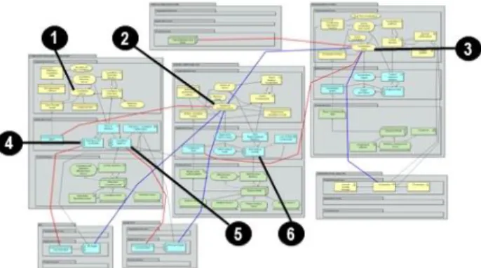
B. Policy semantic investigation
The unitary SCADA component models are used in the second step to picture the global structure of the SCADA architecture and of the connections, in terms of policies, amongst the components of the architecture. Fig. 2 highlights the two types of policies recovered in SCADA architecture:
1) Cognitive Policy
Cognitive Policies [12] are represented in blue in Fig. 2.
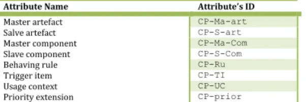
They represent policies which govern the behaviour of one artefact of the component architecture. This policy specifies the rule that the Responsible artefact needs to follow for the execution of a defined activity in a specific execution context. This rule is dictated by the artefact which exists in the same component or in another one. The artefact which generates the policy is the Master artefact and the one which execute it is the Slave artefact. The Cognitive Policy morphology is articulated on the following set of attributes (perceived by [13]): Master artefact, Slave artefact, Master component, Slave component, Behaving rule, Trigger item, Usage context, Priority extension (Table I).
Table I. Cognitive policy attributes’ name and attributes’ ID
Attribute Name Attribute’s ID
Master artefact CP-Ma-art Salve artefact CP-S-art Master component CP-Ma-Com Slave component CP-S-Com Behaving rule CP-Ru Trigger item CP-TI Usage context CP-UC Priority extension CP-prior
The application schema of a CP, as presented in Fig. 2, obeys the two following controls: (1) the communication path is from a Master structural concept to a Slave behavioral concept or (2) the communication path is from a Master behavioural artefact to another Slave behavioural artefact.
Figure 2. Two types of policy for SCADA. CP in blue and PP in red.
1) Permissive Policy
Permissive Policies are represented in red in Fig. 2. They
represent policies which govern the knowledge acquisition rules from the Master to the Slave artefact [14]. This knowledge acquisition traditionally takes the form of SCADA states data accessed or provided in order to provide the Responsible with the access (of in, out, in_out types [16]) to successive Cognitive Policies in case of occurring events. The Permissive Policies morphology is articulated on the following set of attributes [(perceived by [15]): Master artefact, Slave artefact, Master component, Slave component, Permission rules, Pre-permission conditions, Master permission cardinality, Slave permission cardinality, and Cognitive constraints (Table II) - sustained by Cognitive Policy states).
Table II. Permissive Policy attributes’ name and attributes’ ID
Attribute Name Attribute ID
Master artefact PP-Ma-art Slave artefact PP-S-art Master component PP-Ma-Com Slave component PP-S-Com Permission rules PP-Ru Permission conditions PP-Condi Master permission cardinality PP-Ma-Car Slave permission cardinality PP-S-Car Cognitive constraints PP-Co.con.
The application schema of a CP, as highlighted in Figure 2, obeys the two following controls: (1) the communication path is from a Master structural artefact to a Slave informational artefact or (2) the communication path is from a Master behavioural artefact to a Slave informational artefact.
IV. POLICYIDENTIFICATIONMETHOD Designing automatic reaction strategy requires a rigorous two phase’s policy elaboration mechanism:
A. Policy scheme identification steps
The first phase is itself structured in three steps. The first one aims at identifying the structure of the CI architecture in terms of unitary modules (components), including their three layers of abstraction build upon the SCADA metamodel (i.e., organization, application, and technical). The second step aims at identifying the external parameters of the CI such as potential threat probes and indicators that may impact the CI normal functioning (flood, hijacking,…), the physical environment, and/or the contractual SLA (service level agreement). The third step aims at identifying the reaction policies which may be of two types: Cognitive (artefact of a CI component which needs information from succeeding artefacts – Blue connections on Figure 1) or Permissive (artefact of a CI component which needs permission upon the succeeding lower layer artefacts – Red connections on Figure 1). Both types of policies are explained in [1] and [2].
B. Policy scheme formalisation steps
After policies being identified, the second phase of the method aims at formalizing policy scheme using a three steps approach. The first one aims at depicting Master-Slave communication artefacts
(organization-organization, organization-technical, technical-technical), the second aims at identifying the cognitive and permissive behaviour based on the automatic reaction
strategy, and the last one aims at formalizing the policies
accordingly. This latter is function of the policy type and is achieved, on one hand, with the inter-artefacts knowledge requirement, external probes and monitoring tools in case of Cognitive policy and with the reaction strategy with the requirement of access to artefacts in case of Permissive policy.
V. AUTOMATICREACTIONSTRATEGY ARCHITECTURE
Practitioners of the critical infrastructures call for an integrated approach for the architecture components management. However, up to date, the automatic reaction strategy has been perceived and addressed as isolated system. Its integration with the reaction CI components such as the antivirus, firewall, IDS, RTU, correlation engine and so forth has remained lacunar mainly due to the lack of a common representation language. The SCADA component metamodel, supported by the method for policy scheme identification, allows facing this integration by considering the Automatic Reaction Strategy (ARS) as an integral part of the SCADA architecture.
Figure 3. Component’s Policy Path
This ARS is defined by “the rules (r1n) uses by the Main CI Investigator to choose between the available reaction policy (RP1m) option in accordance with the critical infrastructure Expected Automatization Levels (EAL) and considering the RP at the Organization (o) and/or at the Application (a) level. Amongst the main artefacts which
construct the reaction unit supporting the ARS architecture, we denote two main artefacts at the organizational layer (Yellow part of Figure 4):
• The Main CI Investigator which is a type of Business actor, that accesses the Expected Automatization Levels and which is associated to the Organizational Automatic
Reaction Strategy. This Main CI Investigator acts as the
guarantor of the component RPo and RPa [3].
• The Organizational Automatic Reaction Strategy, defines by the rule, is, hence, modelled by means of a
business function. It encompasses the expected automatization according to external constraints, SCADA topology, CI system, Regulatory framework, Security level (provided through CERN papers for instances), and so forth. This expected automatization levels is thus associated to different types of application or organization objects. As illustrated in Figure 2, this business function is correlated to Analytical function policy, correlation policy, or visualisation policy following the reaction architecture modelled using ArchiMate® (see Table I)
from Figure 8.
Figure 4. Reaction Unit
Equivalently, three main artefacts compose the application layer (Blue part of Figure 4):
• The Application Automatic Reaction Strategy, also defined by the rule, is modelled by means of an application function. This latter is also naturally associated to the Expected Automatization Level and is accessed by the Main CI Investigator.
• The Application ARS is associated with the
Detection/correlation collaboration which facilitates the
information exchanges between the CI application modules and realizes the application policy deployment to the CI component application artefacts.
• The Application ARS is also guaranteed by the Main CI
Investigator and is realized following the reaction
architecture from Figure 1, by the Alert analysis Module, the Detection ZW 0.1 Module and the Correlation Application 1.1.
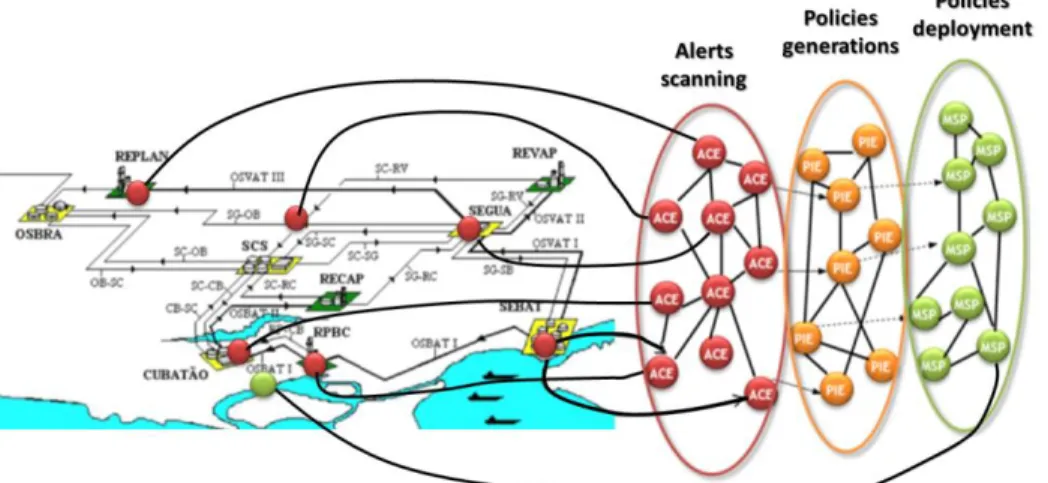
VI. CASE STUDY IN PETROLEUM DISTRIBUTION
INFRASTRUCTURE
The represent the modeling of ArchiMate components metamodel and policy generation, we complete, in this paper, the case study presented in [23]:
Partially represents the real-world petroleum supply chain planning problem of Petrobras […] Petrobras has 59 petroleum exploration sites among which 43 are offshore, 11 refineries that are located along the country’s territory and a large number of facilities such as terminals and pipeline networks. Refinery sites are concentrated mainly in southern [of the country] where 7 sites are found, 4 of which represent 47% of the company’s processing capacity. These refineries are located in the most important and strategic consumer markets. Therefore, the present work addresses the supply chain comprised of these 4 refineries,
terminals compose the storage facilities, namely: SEBAT, SEGUA, CUBATAO, SCS and OSBRA; and a pipeline network for crude oil supply and another for product distribution compose the transportation facilities.
Figure 5. Petroleum architecture plan
The broadcasting mechanism (Figure 6) aims at sending alerts to the authorities using technology such as the SMS or tweets whenever a cyber-attack occurs. This section presents the core components of the broadcasting mechanism. The solution relies on a MAS technology on the top of the JADE framework [6]. SCADA component are disseminated on three layers of the infrastructure corresponding to geographical region (city, region or country) and they retrieve information from probes located in control stations and on the petroleum distribution channel and representing with different values: pressure, CERN alert and estimated cyber-crime level. The components that compose the critical architecture are the following:
The Alert Correlation Engine (ACE) collect, aggregates and analyses information coming from probes deployed over the network and control stations. Confirmed alerts are sent to the Policy Instantiation Engine (PIE). The PIE receives confirmed alert from the ACE, set the severity level and the extent of the geographical response. The PIE instantiates high level alert messages, to be deployed.
Finally the high level alert messages are transferred to the Message Supervising Point (MSP). The MSP, as explained in detailed in [9] is composed of two modules. The Policy Analysis (PA) is in charge of analysing the policies previously instantiated by the PIE. For that, the Policy Status database stores all communication policies and their current status (in progress, not applicable, by-passed, enforced, removed…) so that the PA module can check the consistency of the newly received message to be deployed. The second module is the Component Configuration Mapper that selects the appropriate communication channel. Figure 7 presents two different kinds of Message Broadcasting Point (MBP). Indeed, another advantage of MAS is that it is easy to implement from a model, specific components in order to perform specific tasks. Concretely it enables us to use different channel of communication (e.g. SMS, e-mail, micro-blogging) to send alerts to citizens, hospitals, etc. By this way our petroleum supply interruption prevention system is easily extensible for future communications facilities. MBPs receive generic alert messages from the MSP. Then a specific parser converts the incoming alert message to the appropriate format according to the channel.
To consider the mutual trust between components, each component maintains within it a database of levels of trust towards its pairs. This means e.g. that the MBP has a dedicated level of trust for the ACE and the MSP.
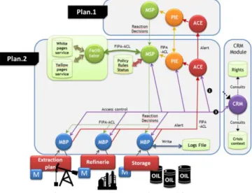
The broadcasting alert architecture presented in this section is based on the ReD project [7]. The ReD (Reaction after Detection) project defines and designs a solution to enhance the detection/reaction process and improves the overall resilience of critical infrastructures. Figure 8 introduces the developed architecture illustrated with our cyber intrusion alert system. The flow is supposed to begin with an alert detected by a probe.
Figure 6. Broadcasting mechanism inside This alert is send to the ACE component (City layer) that does
or does not confirm the alert to the PIE. Afterwards, the PIE decides to apply new policies or to forward the alert to an ACE from a higher layer (Region Layer). The PIE component sends the policies to the MSP component, which decides
which MBP is able to transform the high level alert message into an understandable format for the selected communication channel.
In order to manage access rights, we have incorporated to ReD a Context Rights Management module (CRM). Block on the
right on Figure 9. The CRM is in charge of providing access rights to components. The CRM uses the component links and the crisis context database. The first database includes the link between two components (type of contextual access right). The second database includes a set of crisis contexts. Thanks to these databases the CRM component is able to detect the component right to access each other’s at the operational layer depending on the context.
Figure 7. Detailed reaction architecture
A. ACE Organizational layer
In the Organizational layer of the ACE Component (Figure 11) we have represented separately the monitoring aspect from the transaction aspect. We call a transaction a communication of information from one component to another (e.g. the ACE sends an alert to a PIE) and then we consider the monitoring as the representation of information from an external device. Firstly the Organizational Role of the ACE is represented as a
Collaboration of the PIE Role and the Device Role. Each Role
of the Collaboration communicates with the ACE through a proper Organizational Interface one for the monitoring and another one for the transaction. ACE Role is providing two
Organizational Services depending on only one
Organizational Policy which is dealing with two Events
respectively for the monitoring and the transaction. Secondly the two Organizational Services provided by the ACE component are regrouped into a correlation service symbolized by the Product concept. This Product has the objective Value to reduce a crisis by giving a guaranty of short reaction time represented by the Contract concept. Finally the
Contract is applied on Organizational Object as monitoring
information and transaction information.
B. ACE Application layer
For the Application layer of the ACE Component (Figure 11) we found the separation between the transaction and the monitoring. Application Services for transactions and monitoring are, as in the Organizational Policy, linked to only one Application Policy. To highlight the collaboration between the ACE and the Monitored Device, we created a
Collaboration concept named Monitoring Administration and
shows that this collaboration is constituted of the Components
of the ACE and the Components of the Device. Device’s
components use the Application Monitoring Interface to communicate with the ACE’s components and the ACE’s components are composed of the Application Monitoring
Interface. We use the same approach for the transaction part
and rapidly show that the ACE’s components are composed of two interfaces deserving the two Application Services. Again the Application layer contains Data Object as Transaction
Messages and Monitoring Messages used by the different Application Components of the layer.
Figure 8. ACE component model
C. ACE Technical layer
We found in the Technical layer of the ACE Component (Figure 11) another representation of the two collaborators of the ACE component. Transaction and Monitoring Infrastructure are separated from each other. Both of them
have Infrastructure Service connected to the ACE component’s Node and an Infrastructure Interface where the collaborators can interact with it. Each Node is respectively connected to a Communication Path (represented by a logical
Event Queuing) and uses different Artifacts to communicate.
We have intentionally not instantiated Nodes for readability but the reader can easily imagine that an ACE component can be deployed on a computer who’s running an operating system. Also the Network concept is not defined in our instantiation for the same reason. For example Monitoring
Event Queue between the ACE component and the Device can
be represented as a Network concept, as an USB cable and for the Transaction Event Queue by an RJ45 cable.
D. ACE Organizational Policy
To illustrate the Organizational Policies of the ACE we choose to represent the monitoring part of the ACE Role as an
UML Use Case. Monitoring Events are illustrated in the Use Case as Extension Points and show their impacts on the
behaviours realized in the Perform Monitoring Policy. Roles are presented as Actors and Collaborations are highlighted by the different link between the behaviours.
E. ACE Application Policy
Sequences Diagrams have been used to represent the
behaviours performed by the Application Domain of the ACE
Component for the Application Policy: Perform Detection. In
the Sequence Diagram, behaviour of each component is fit to his lifeline and in/out Events presented as inter-component methods call. Context analyse is performed by the component during the execution of his behaviour.
VII. CONCLUSIONSANDFUTUREWORKS We have elaborated an innovative version of ArchiMate® to enrich the SCADA components collaborations and, more particularly, the description of the components behavior endorsed in the policy for cyber-crime mitigation. To illustrate our work, a case study has been performed in the frame of a critical infrastructure related to petroleum supply. This case study has allowed illustrating and validating the definition of policies according to reaction strategy on the first hand, and depending on evolving trust parameters amongst components on the other hand. Finally, we have simulated a heterogeneous network of ACE and PIE components and where different load of malicious components have been integrated.
The three functions necessary for the enhancement of the SCADA architecture management with the automatic reaction strategy proposed in this paper are:
The 1st function aims to support the modelling of SCADA
components using the generic SCADA language grounded on the metamodel for SCADA components. This latter allows modelling each component of a SCADA architecture following a unique modelling architecture in three abstraction layers and enhances the ArchiMate® modelling language with
the policy concept as a specialization of an organizational/application service. This policy is refined using the 2nd function onto cognitive or permissive policies and these
latter semantically enrich the connection between the concepts which realizes the SCADA architecture. The 3rd function
depicted in this paper proposes a two phase’s method for Automatic reaction strategy based upon the two succeeding functions.
As future works, additional validations are expected in the next months on larger scale infrastructures. In parallel, a supporting tool is being developed. The upper validation has been allowed by the primary functionalities of it. Additional features of that latter will allow modulating the environment parameters in which the SCADA components’ network is running and thereby, it will allow refining and validating the trust based policies evolution along more complex situations.
ACKNOWLEDGEMENT
This research is funded by European FP7-Security project “CockpiCI”, Cybersecurity on SCADA: risk prediction, analysis and reaction tools for Critical Infrastructures.
REFERENCES
[1] F. Zambonelli, N. R. Jennings, and M. Wooldridge. 2003. Developing multicomponent systems: The Gaia methodology. ACM Trans. Softw. Eng. Methodol. 12, 3 (July 2003), 317-370.
[2] V.Torres da Silva, R. Choren, and C. J. P. de Lucena. 2004. A UML Based Approach for Modeling and Implementing Multi-Component Systems. In Proceedings of the Third International Joint Conference on Autonomous Components and Multicomponent Systems - (AAMAS '04), Vol. 2. IEEE Computer Society, Washington, DC, USA, 914-921. [3] J. J. Gomez-Sanz, J. Pavon, and F. Garijo. 2002. Metamodels for
building multi-component systems. Proceedings of ACM symposium on Applied computing (SAC '02). ACM, New York, NY, USA, 37-41. [4] G. Beydoun, C. Gonzalez-Perez, G. Low, and B. Henderson-Sellers.
2005. Synthesis of a generic MAS metamodel. SIGSOFT Softw. Eng. Notes 30, 4 (May 2005), 1-5.
[5] AUML (Component UML), http://www.auml.org/
[6] http://www.cs.rmit.edu.au/components/SAC2/methodology.html [7] G. Guemkam, C. Feltus, C. Bonhomme, P. Schmitt, B. Gâteau, D.
Khadraoui, Z. Guessoum, Financial Critical Infrastructure: A MAS Trusted Architecture for Alert Detection and Authenticated Transactions, IEEE SAR/SSI2011), France
[8] C. Feltus, E. Dubois, E. Proper, I. Band, M. Petit, Enhancing the
ArchiMate® Standard with a Responsibility Modeling Language for
Access Rights Management, 5th ACM SIN 2012, India.
[9] G. Neumann and M. Strembeck. A scenario-driven role engineering process for functional rbac roles. In SACMAT '02, New York, NY, USA, 2002. ACM.
[10] J. A. Zachman. 2003. The Zachman Framework For Enterprise Architecture : Primer for Enterprise Engineering and Manufacturing By. Engineering, no. July: 1-11.
[11] UML 2 ( http://www.uml.org/)
[12] W. Jiao; Z. Shi; A dynamic architecture for multi-component systems, Technology of Object-Oriented Languages and Systems, 1999. TOOLS 31. pp.253-260.
[13] C. Feltus, D. Khadraoui and J. Aubert. A Security Decision-Reaction Architecture for Heterogeneous Distributed Network. 2012 Seventh Int. Conference on Availability, Reliability and Security. IEEE.
[14] J. Sabater and C. Sierra, Review on computational trust and reputation models, Artificial Intelligence Review, vol. 24, no. 1, pp. 33–60 [15] G. Guemkam, D. Khadraoui, B. Gâteau, Z. Guessoum, ARMAN:
Component-based Reputation for Mobile Ad hoc Networks. 11th
Conference PACMC. May 2013.
[16] G. Eason, B. Noble, and I.N. Sneddon, “On certain integrals of Lipschitz-Hankel type involving products of Bessel functions,” Phil. Trans. Roy. Soc. London, vol. A247, pp. 529-551, April 1955.
[17] J. Clerk Maxwell, A Treatise on Electricity and Magnetism, 3rd ed., vol. 2. Oxford: Clarendon, 1892, pp.68-73.
[18] I.S. Jacobs and C.P. Bean, “Fine particles, thin films and exchange anisotropy,” in Magnetism, vol. III, G.T. Rado and H. Suhl, Eds. New York: Academic, 1963, pp. 271-350.
[19] K. Elissa, “Title of paper if known,” unpublished.
[20] R. Nicole, “Title of paper with only first word capitalized,” J. Name Stand. Abbrev., in press.
[21] Y. Yorozu, M. Hirano, K. Oka, and Y. Tagawa, “Electron spectroscopy studies on magneto-optical media and plastic substrate interface,” IEEE Transl. J. Magn. Japan, vol. 2, pp. 740-741, August, p. 301, 1982. [22] M. Young, The Technical Writer’s Handbook. Mill Valley, CA:
University Science, 1989.
[23] Sérgio M.S. Neiro, José M. Pinto, A general modeling framework for the operational planning of petroleum supply chains, Computers & Chemical Engineering, Volume 28, Issues 6–7, 15 June 2004, Pages 871–896.
![Figure 1: Three layers of SCADA system metamodel extracted from [2]](https://thumb-eu.123doks.com/thumbv2/123doknet/14517361.721962/4.893.442.785.494.873/figure-layers-scada-metamodel-extracted.webp)