HAL Id: hal-01120117
https://hal.inria.fr/hal-01120117
Submitted on 24 Feb 2015
HAL is a multi-disciplinary open access
archive for the deposit and dissemination of
sci-entific research documents, whether they are
pub-lished or not. The documents may come from
teaching and research institutions in France or
abroad, or from public or private research centers.
L’archive ouverte pluridisciplinaire HAL, est
destinée au dépôt et à la diffusion de documents
scientifiques de niveau recherche, publiés ou non,
émanant des établissements d’enseignement et de
recherche français ou étrangers, des laboratoires
publics ou privés.
A Reconfigurable Component Model for HPC
Vincent Lanore, Christian Pérez
To cite this version:
Vincent Lanore, Christian Pérez. A Reconfigurable Component Model for HPC. [Research Report]
RR-8674, ENS Lyon. 2015, pp.17. �hal-01120117�
0249-6399 ISRN INRIA/RR--8674--FR+ENG
RESEARCH
REPORT
N° 8674
January 2015Component Model for
HPC
RESEARCH CENTRE GRENOBLE – RHÔNE-ALPES
Inovallée
Vincent Lanore, Christian Pérez
Project-Team Avalon
Research Report n° 8674 — January 2015 — 18 pages
Abstract: High-performance applications whose structure changes dynamically during execu-tion are extremely complex and costly to develop, maintain and adapt to new hardware. Such applications would greatly benefit from easy reuse and separation of concerns which are typical advantages of component models. Unfortunately, no existing component model is both HPC-ready (in terms of scalability and overhead) and able to easily handle dynamic reconfiguration.
We aim at addressing performance, scalability and programmability by separating locking and synchronization concerns from reconfiguration code. To this end, we propose directMOD, a com-ponent model which provides on one hand a flexible mechanism to lock subassemblies with a very small overhead and high scalability, and on the other hand a set of well-defined mechanisms to easily plug various independently-written reconfiguration components to lockable subassemblies. We evaluate both the model itself and a C++/MPI implementation called directL2C.
Key-words: Component models, High-performance computing, Dynamic reconfiguration, For-mal models
Un modèle à composants reconfigurable pour le calcul haute
performance
Résumé : Les applications de calcul scientifique dont la structure change à l’exécution sont particulièrement difficiles à développer, maintenir et adapter à du nouveau matériel. De telles applications bénéficieraient grandement de la séparation de préoccupations et e la réutilisation, qui sont des avantages typiques des modèles à composants. Malheureusement, aucun modèle à composants existant n’est à la fois assez performant pour le calcul haute performance (en termes de surcoût et de passage à l’échelle) et capable de gérer la reconfiguration à l’exécution.
Nous proposons de régler les problèmes de passage à l’échelle, de performance et de pro-grammabilité en séparant les problématiques de verrou du code de reconfiguration. À cette fin, nous proposons directMOD, un modèle à composants qui fournit d’une part un mécanisme flexi-ble et peu coûteux de verrouillage de sous-assemblage et d’autre part un ensemflexi-ble de mécanismes bien définis permettant de facilement composer des codes de reconfigurations. Nous évaluons le modèle lui-même ainsi qu’une implémentation, directL2C.
Mots-clés : Modèles à composants, calcul haute performance, reocnfiguration dynamique, modèles formels
1
Introduction
High Performance Computing (HPC) deals with maximizing the performance of an application, in particular for high-end hardware such as computer clusters and supercomputers. HPC ap-plications are apap-plications whose execution on traditional computers would be impractical, e.g, because it would take years or require inordinate amounts of resources. Examples include large numerical simulations, brute force code breaking, large parameter space exploration. . . Since com-puting time on large HPC platforms is costly, increased performance leads to lower costs and better results because more computing can be done in the same amount of time. Performance is thus paramount in HPC.
To maximize performance, many HPC applications are manually optimized specifically for each target hardware. This optimization process is complex and requires the programmer to be an expert in various topics including the functional part of the application, low-level hardware concerns and parallelization concerns. Moreover, hardware-specific optimization leads to highly specialized code which is difficult to reuse. These issues are amplified by the complexity and size of HPC applications, by the complexity of HPC hardware and by the constant need to adapt existing code to new architectures.
Component-based approaches are known to improve separation of concerns and reuse, and there exist some HPC component model such as CCA [4] or L2C [5]. Separation of concerns diminishes the amount of skills required for a single programmer while reuse eases the adaptation process to new architectures. Case studies on HPC applications such as Jacobi [5] or Fast Fourier Transforms [16] have shown that components optimized for low-level concerns could be reused in several specialized assemblies.
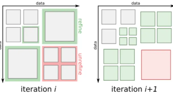
However, some HPC applications have a structure which changes dynamically during ex-ecution. Examples include applications with dynamic load balancing, non-trivial deployment schemes and Adaptive Mesh Refinement (AMR). AMR is a technique used in numerical compu-tation on meshes (typically, differential equation solving) which consists in refining or unrefining the mesh during computation so that, locally, the refinement level matches the desired precision (see Figure 1). Many executing AMR applications exhibit a natural tree structure (refining adds children to a node while unrefining removes them).
This paper focuses on AMR as an example to highlight the need of a reconfigurable HPC component. The point of AMR is to have both high precision and a manageable computing cost but the downside is that it is a complex technique to implement and optimize which has been the topic of extensive research. Traditional implementations (e.g, [12]) explicitly store the AMR tree structure on all nodes. This approach costs O(p) memory per node, locating a neighbor in the tree costs log(p) and reconfiguration requires to update every single node. These costs become problematic as the size of problems increase and hamper scalability on large scale systems. Recent advances (e.g, [13, 15]) advocate low synchronization and propose to store only local structure data on each node.
Moreover, as programming a specific AMR application is usually a large undertaking, most use independently-developed frameworks. Such frameworks [9, 14, 17] are massive and complex codes whose optimization and fine-tuning are difficult for the end user.
In component terms, applications such as AMR require dynamic reconfiguration of the as-sembly which is an active and challenging research topic. Moreover, easy and meaningful reuse of third-party code would largely help with optimizing AMR frameworks for specific problems ans architectures. Unfortunately, to our knowledge, no existing component model is efficient enough (in terms of scalability and overhead) to be used in HPC, capable of easily handling low-synchronization distributed reconfiguration and capable of easy reuse of reconfigurable com-ponents.
4 Vincent Lanore, Christian Pérez
Figure 1: An AMR iteration example on a 2D grid. Each square corresponds to the data handled by one thread and every square has the same resolution. Green denotes refinement and red unrefinement. In this case refinement is done recursively into 4 data squares.
To solve this issue, this papier proposes a new approach in the form of a component model which is called directMOD. Scalability is achieved thanks to arbitrary assembly-defined locking units which can be tailored to specific applications. To improve reuse and separation of concerns, directMOD enables transformations to be independently developed of the rest of the application and then plugged to the assembly.
The structure of this paper is as follows: Section 2 presents related works on dynamic re-configuration and analyzes them from a HPC perspective; Section 3 describes the directMOD component model; Section 4 evaluates and illustrates directMOD on some examples; Section 5 presents and evaluates directL2C , an implementation of directMOD and finally, Section 6 con-cludes the paper.
2
Related Work
2.1
Reconfigurable Component Models
Among component models which support dynamic reconfiguration, three broad categories can be distinguished:
Centralized reconfiguratio. Component models with centralized reconfiguration rely on a full representation of the assembly to accomplish reconfigurations. For this representation to stay consistent during execution, these approaches require global synchronization, e.g, global barrier, global lock. Examples of such models include global MAPE loops.
While this approach makes sense for moderate-scale distributed systems up, HPC is now targeting very large scale such that global synchronization is a too costly operation. Applications such as the AMR actually perform many fine-grain local reconfigurations; stopping such an application completely at every reconfiguration would slow it down considerably. For this reason, centralized reconfiguration is not suited for HPC applications.
Unrestricted Reconfiguration Many component models offer basic low-level reconfigura-tion primitives (i.e, create, destroy and connect operareconfigura-tions) without higher-level reconfigurareconfigura-tion support. In practice, many component model implementations based on objects offer these oper-ations whether or not they appear in the model itself. Examples of such models/implementoper-ations include CCA [4] and L2C [5].
Although it is possible to program reconfiguration in these implementations, the model does not provide any tool to conjointly use several third-party reconfiguration components nor to help designing efficient reconfiguration. Indeed, without any form of synchronization between reconfiguration operations, it is impossible to keep a consistent representation of the assembly since other components might reconfigure any part of it at any time.
Controllers along Hierarchy Some hierarchical component models allow distributed recon-figuration to be carried out at composite-level. Examples of such models include FRACTAL [6], BIP [2, 3], SOFA [8], or more recent research [10, 11].
These models can be used to implement efficient distributed reconfigurations while preserv-ing consistency durpreserv-ing execution. However, the reconfiguration scope is restricted to composites which does not fit the structure of many HPC applications. For example, AMR will require neighbor-to-neighbor synchronization on a mesh structure which makes it very complex to man-age inter-branch communications when map on a tree-like component hierarchy.
2.2
Other Approaches
Dynamic Software Updating Dynamic Software Updating (DSU) is a common reconfigu-ration problem which deal with updating a software (i.e, update its code) without stopping it. Recent examples include [7].
DSU is mostly irrelevant in an HPC context. Indeed, HPC applications are very complex and would be very difficult to reconfigure without raising consistency problems; also, continuity of service is irrelevant in HPC as only the final result usually matters. For these reasons, we do not consider DSU-like constraints and goals in this paper.
MAPE MAPE (Monitor Analyze Plan Execute) is a commonly found approach to dynamic reconfiguration. It consists in having a reconfiguration architecture (executing alongside the assembly to reconfigure) which has a representation of the assembly, monitors it, analyzes what it monitors to know when reconfiguration must be done, plans necessary reconfiguration operations while the assembly is still running and finally executes planned changes before starting over. MAPE loops can be global (i.e, maintain a representation of the full applications) which is an inherently non-scalable approach or can be distributed (i.e, several local MAPE loops running concurrently) which poses the problem of consistency across concurrently-managed subsets of the application.
Although distributed MAPE loops can be relevant for some HPC applications, they do not trivially allow application-driven reconfiguration (i.e, reconfiguration is triggered by functional components) as can be found in AMR for example. For this reason, we consider the MAPE approach orthogonal to the goals of this paper: they must be implementable to some extent as they are a fairly straightforward and natural way to deal with reconfiguration but they are not the only type of reconfiguration pattern we want to consider.
3
The d irectMOD Component Model
3.1
Overview
This section describes directMOD, a component model whose goal is to enable scalable assembly reconfiguration at runtime, and to have good software engineering properties, i.e, reuse and separation of concerns, even when assembly transformation is involved.
6 Vincent Lanore, Christian Pérez
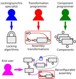
Figure 2: An overview of separation of concerns as enforced by directMOD.
First, it adopts the quiescent state approach, i.e, to reconfigure a part of the assembly this part needs to be stopped/locked. However, to achieve scalability the unit of locking, i.e, the smallest parts of an assembly which can be locked, is defined arbitrarily at assembly-level and is not imposed by the model. For example, this means that individual ports can be locked as well as full chunks of assembly, depending of the application. That way, locking can be tailored to each application and can be arbitrarily distributed (for maximum scalability) or centralized (e.g, for easy consistency). We call these lockable units domains.
Second, since reconfiguration occurs on locked parts of the assembly, having those parts being arbitrary could cause issues to use independently-written reconfiguration code with a given lock-ing scheme. To circumvent this problem, transformations (i.e, reconfiguration code) are defined independently and plugged to domains at assembly-level using a device called transformation adapters. Transformations adapters allow to plug a transformation to a specific subset of a domain.
With these two ideas, we identify 4 possible programmer/user roles in directMOD which are presented in Figure 2. Component programmers write traditional components; transforma-tion programmers write transformatransforma-tions using the model; domain programmers implement the domains and are responsible for all the locking code; finally, the end users can assemble every-thing using traditional component connexions, domains for the locking logic and transformation adapters to plug transformations.
Section 3.2 defines directMOD assemblies while Section 3.3 presents a semantic for it.
3.2
Definitions
Definitions are presented in a top-down fashion to give a clear idea of the structure of directMOD. Let assume that R is a set of named hardware/software resources (e.g, CPU cores, computing node) and that C is a set of component types.
Definition 3.1. An assembly α is a sextuplet:
α = (C, P, R, T, o, r)
C is a set of components; P is a set of ports; R ⊆ R is a set of resources; T is a set of transformations.
o : P → C ∪ {⊥}is the owner function and denotes which port belongs to which component. Let p ∈ P and c ∈ C, o(p) = c means that port p belongs to component c. Mapping to ⊥ means the owner is undefined.
r : C ∪ P → P(R) ∪ {⊥}is the localization function and denotes which component/port is located on which resource(s). Let c be a component and R0 ⊆ R then r(c) = R0 means that
component c is located on all resources in R01. Mapping to ⊥ means the component or port
localization is undefined.
Components, ports and transformations are defined extensively hereafter. This paper assumes the existence of component types and resources since they are not its focus.
Let denote A(C, R) the set of assemblies on resources R using component types C. Let denote compo(α) = C, ports(α) = P , resources(α) = R, transfo(α) = T , owner(α) = o, loc(α) = r. Let denote support(α) = C ∪ P ∪ R and cp(α) = C ∪ P .
When a component or port has an undefined owner or localization (i.e, when it is mapped to ⊥), it means that the assembly is incomplete, e.g, it is a part of a bigger subassembly. An assembly which is supposed to describe a complete (i.e, deployable) application should not have any undefined owners or localizations.
Note that each port can belong to only one component.
Definition 3.2. α = (C, P, R, T, o, r) is a subassembly of β = (C0, P0, R0, T0, o0, r0) iff C ⊆ C0∧ P ⊆ P0∧ R ⊆ R0∧ T ⊆ T0∧ o0|
P = o ∧ l0|P ∪C = l.
Let denote α ⊆ β and subassemblies(β) = {α|α ⊆ β}. Definition 3.3. A component is of the form:
Component ::= (instance(T ype), N ame) | (domain(Subassembly), N ame)
A component instance(t), t ∈ C, called a basic component, is an instance of component type t. A component c = domain(α), α ∈ A(C, R), called a domain, is a special component which is responsible for the locking of an assembly α during execution.
Definition 3.4. A transformation τ is of the form: τ = ((α, ω, s, t), N ame)
α ∈ A(C, R)is the origin of the transformation, i.e, the assembly on which the transformation is applied.
ω ∈ A(C, R)is the destination of the transformation, i.e, the end result of the transformation. s : cp(α) → cp(ω) ∪ {⊥}is called the state mapping and denotes which component and ports are copied over through the transformation (those mapped to ⊥ are destroyed).
t : support(α) → support(ω) ∪ {⊥}is called the topology mapping and denotes which compo-nent takes the role of which one in the final assembly.
Let denote T (C, R) the set of all transformations, origin(τ) = α, destination(τ) = ω, state(τ ) = s, and topo(τ) = t.
Definition 3.5. The composition of the transformations τ = (α, ω, s, t) and υ = (α0, ω0, s0, t0), denoted τ+υ, is (α∪α0, ω∪ω0, s00, t00)where s00(x) = s0(x)if s0(x)is defined, otherwise s00(x) = t(x)
if s(x) is defined, otherwise s00(x) =⊥and where t00 is defined the same way as s00.
1Components and ports can be located on several resources, although ports located on several resources do
8 Vincent Lanore, Christian Pérez Note that composition is not symmetric and that the second transformation can overwrite the mappings of the first.
Definition 3.6. A port is of the form:
P orts = (set of BasicP ort, P ortN ame) BasicP ort ::=⊥ | ref (P ortN ame) | adapter(T ransf ormation, Subassembly)
ref (P ortN ame)means the port is connected to another port. ⊥ represents a unset reference. adapter(Transformation, Subassembly) is called a transformation adapter and it is a port from which a transformation T ransformation can be applied to subassembly Subassembly ∈ A(C, R) Note that components, ports, resources and transformations are named. Set operations on supports (e.g, ∪ in transformation composition) take names into account (in a set, two compo-nents/ports/resources which are otherwise identical must have different names). Names serve two purposes: to identify a component/port/resource from a subassembly to the corresponding component in the larger assembly and to allow for fine control when composing transformations (this is illustrated in Section 4.2).
We denote fullsupport(α), α ∈ A(C, R) the union of all the ports, components and resources which appear in α or any domain or transformation adapter recursively.
We say that two assemblies α an β are equivalent, denoted α ≡ β, if they are identical up to renaming and a permutation on their full supports.
If two assemblies are equivalent, there exist bijective mappings between their full supports which preserve structure. We assume a total order on such mappings and call default mapping the minimum mapping with regard to that order. We denote dm(α, β), α ≡ β the default mapping between α and β.
Because of space limitation, extensive definitions of full supports, equivalence and default mapping are note given here; all of them are however straightforward.
Definition 3.7. An assembly α is well-formed iff a) all its domains are disjoint; b) every domain is in subassemblies(α); c) no domain contains another domain; d) ∀τ ∈ transfo(α), origin(τ) and α have disjoint component and port sets; e) every adapter a = adapter(τ, β) verifies β ⊆ α, τ ∈ transf o(α)and β ≡ origin(τ); f) for every port of the form p = ref(P ortName), there is indeed a port named P ortName.
In the rest of the paper, we assume that all assemblies are well-formed.
3.3
Semantics
The previous section has presented the definitions and syntax of directMOD. This section de-scribes its transformation semantics as well as possible operational semantics for a reconfigurable assembly.
Transformation Semantics A transformation τ = (α, ω, s, t) applied to a subassembly β0= (C0, P0, R0, T0, o0, r0) of an assembly β = (C, P, R, T, o, r) such that α ≡ β0 and β0 ⊆ β results in an assembly β00 = (C00, P00, R00, T00, o00, r00) denoted β00 = apply(β, β0, τ ). Let denote m the
default mapping from α to β0 and m−1 its inverse.
Figure 3 shows the various assemblies and subassemblies mentioned in the definition as well as the relations between them.
Figure 3: The various assemblies and relations between them during a transformation applica-tion.
The application of a transformation basically consists in: a) replacing β0(where the
transfor-mation is applied) with ω (the result of the transfortransfor-mation); b) copying components and ports which are mapped by s, erasing old values; c) updating references, owners and subassemblies so that, if ∃x ∈ support(β0)such that t(m−1(x)) 6=⊥ then everything pointing to x now points
to t(m−1(x))and that everything including x now includes t(m−1(x)). Transformations are
de-scribed with the following operations: f[x ← y] to replace the value of f(x) with y, as well as x ← y to denote that x now equals y.
β00 = (C00, P00, R00, X00, o00, l00p, l00c) is constructed through the following operations performed in sequence:
• Support: support(β00) ← (support(β) \ support(β0)) ∪ support(ω)
• Transformations: transfo(β00) ← transf o(β).
• Owner: o00← oand then ∀x ∈ ports(ω), o00[x ← owner(ω)(x)].
• Localization: r00← r and then ∀x ∈ cp(ω), r00[x ← loc(ω)(x)].
• State: ∀x ∈ cp(β00) \ cp(ω), if exists y ∈ cp(α) such that s(y) = x then x ← m(y).
• Topology: ∀x ∈ support(β0) such that t(m−1(x)) 6=⊥for every y ∈ cp(β00) \ cp(ω) a) if
r00(y) = x then r00[y ← t(m−1(x))]; b) if y = ref(x) then y ← ref(t(m−1(x))); c) if o(y) = xthen o00[y ← t(m−1(x))]; d) if y is a domain that contains x then y now contains t(m−1(x)); e) if y is a transformation adapter whose paired subassembly contains x then y’s paired subassembly now contains t(m−1(x)).
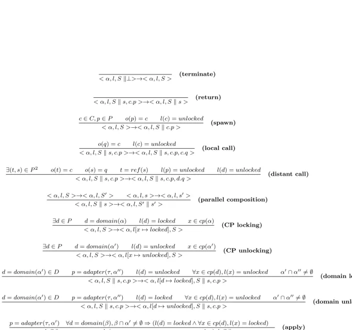
Operational Semantics Let now describe an operational semantics for the execution of a directMOD assembly. This semantic is based on method call stacks defined hereafter and its rules are given in Figure 4.
Basically, this semantics implements multithreaded method call stacks with non-deterministic method calls. Non-determinism models separation of concerns, i.e, the fact that the behaviour of components is not known at assembly-level is beyond what is explicit in the assembly.
Locking a port or a component means that this component/port can no longer be used. Domain locking is modeled as non-deterministic locking of all its elements. The fact that domain locking will not cause deadlocks is guaranteed by the domain programmer; this guarantee is not modeled by the semantics.
Transformations can occur on domains which have been fully locked and in which no method is currently executing. Again, the fact that no method is still executing when the domain is fully locked must be guaranteed by the domain programmer and is not modeled at assembly-level. Definition 3.8. An assembly call state is of the form:
10 Vincent Lanore, Christian Pérez
M ethod ::= Component.P ort T hread ::=⊥ |T hread, M ethod CallState ::= T hread|CallState k T hread State ::=< Assembly, LockingState, CallState >
where the locking state of an assembly α ∈ A+ is the function l : cp(α) → {locked, unlocked} These semantic rules serve several purposes: a) it specifies unambiguously how an assembly behaves; Section 4 refers to them in several places and illustrates them; b) although we do not have the space to do it here, several properties can be proved from the semantics such that it is indeed executable with only local knowledge or that it preserves well-constructedness of the assembly.
4
Evaluation: Reuse and Separation of Concerns at
Model-level
This section illustrates and evaluates directMOD based on examples of assemblies of increasing complexity. Section 4.1 introduces the base example, that is made of simple ring assemblies. Section 4.2 adds simple dynamic load balancing and shows the reuse capabilities of the model. Section 4.3 deals with an overview of an assembly inspired by an AMR use case. Finally, Sec-tion 4.4 discusses the capabilities of the model as illustrated by the examples.
4.1
Ring Assemblies
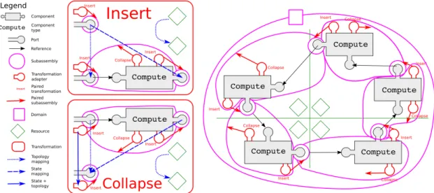
Figure 5 presents a simple distributed ring of p Compute (ComPute) components. We assume each of these components runs iteratively: it receives some data from its predecessor, does some computation, sends data to its successor and starts over. In this first example, there is one global domain which implements a global lock on everything for reconfigurations.
We also assume these components can decide, at the end of any iteration, to add a component next to them or to remove themselves from the ring, i.e, they implement a basic 1D AMR. Fig-ure 5 also graphically describes the Insert and Collapse transformations required to implement this behaviour.
Figure 6 presents a second assembly which contains the same components but now each component has its own domain attached. In this second assembly, all transformation need only lock O(1) components instead of O(p) in the first one which is inherently more scalable. Note that the two transformations defined above still operate correctly in this second assembly despite a different locking scheme. Also note that Insert and Collapse require the locking of only a single domain.
4.2
Adding Load Balancing
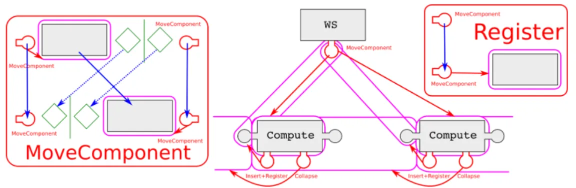
Figure 7 presents a ring assembly variant which now comprises a kind of work stealing infras-tructure in the form of WS components connected also in a ring for sake of simplicity. These components have ports pointing to the components they manage (in this case, all Compute com-ponents on the same resource). We assume that WS comcom-ponents monitor the local computation and ask for more work one of their neighbouring WS components if there is not enough locally.
< α, l, S k⊥>→< α, l, S > (terminate) < α, l, S k s, c.p >→< α, l, S k s > (return) c ∈ C, p ∈ P o(p) = c l(c) = unlocked < α, l, S >→< α, l, S k c.p > (spawn) o(q) = c l(c) = unlocked < α, l, S k s, c.p >→< α, l, S k s, c.p, c.q > (local call)
∃(t, s) ∈ P2 o(t) = c o(s) = q t = ref (s) l(p) = unlocked l(d) = unlocked
< α, l, S k s, c.p >→< α, l, S k s, c.p, d.q > (distant call) < α, l, S >→< α, l, S0> < α, l, s >→< α, l, s0> < α, l, S k s >→< α, l, S0k s0> (parallel composition) ∃d ∈ P d = domain(α) l(d) = locked x ∈ cp(α) < α, l, S >→< α, l[x 7→ locked], S > (CP locking) ∃d ∈ P d = domain(α0) l(d) = unlocked x ∈ cp(α0) < α, l, S >→< α, l[x 7→ unlocked], S > (CP unlocking)
d = domain(α0) ∈ D p = adapter(τ, α00) l(d) = unlocked ∀x ∈ cp(d), l(x) = unlocked α0∩ α006= ∅
< α, l, S k s, c.p >→< α, l[d 7→ locked], S k s, c.p > (domain locking)
d = domain(α0) ∈ D p = adapter(τ, α00) l(d) = locked ∀x ∈ cp(d), l(x) = unlocked α0∩ α006= ∅
< α, l, S k s, c.p >→< α, l[d 7→ unlocked], S k s, c.p > (domain unlocking)
p = adapter(τ, α0) ∀d = domain(β), β ∩ α06= ∅ ⇒ (l(d) = locked ∧ ∀x ∈ cp(d), l(x) = locked)
< α, l, S k s, c.p >→< apply(∪γ∈{β,∃d=domain(β)∧β∩α06=∅}γ, α0, τ ), l, S k s, c.p >
(apply)
∃q ∈ ports(α), owner(α)(q) = c l(q) = unlocked τ ∈ transf o(α)
< α, l, S k s, c.p >→< α[q ← adapter(τ, (∅, ∅, {r(q)}, transf o(α), fports(α), fcp(α)))], l, S k s, c.p >
(create domain)
12 Vincent Lanore, Christian Pérez
Figure 5: A directMOD assembly showing a ring of components distributed across 4 resources with one global domain.
Figure 6: The same assembly as Figure 5 with a local locking scheme (one domain per computing component).
Figure 7 presents the MoveComponent transformation which implements the actual work steal-ing while 7 presents the Register transformation which adds a new component to the work stealing infrastructure. Note that the previous Collapse transformation is compatible with this new architecture without requiring any modification (connexions to removed components are removed automatically, see Section 3.3) while Insert needs only to be composed with Register to work as expected (i.e, so that the new component is registered).
Note that we could also (but do not present extensively here for space reasons) add another infrastructure with a similar structure as the work stealing example (e.g, a logging infrastructure) without writing any new transformation. Indeed, composing Register with Insert again takes care of registering new created components, MoveComponent can be composed with itself to
Figure 7: A partial directMOD assembly showing the extra transformations and infrastructure required to add work stealing to the previous ring example. The assembly shown is only what is on one resource.
handle both manager changes when moving a component and Collapse still works as is. Finally, note that the work stealing components and transformations are in no way specific to this ring example and could be used in assemblies with different structures.
4.3
Adaptive Mesh Refinement
In addition to the simple ring examples presented above, directMOD has also been used on an AMR assembly which matches more closely the structure of an actual complex HPC application. More specifically, we have made a 2D grid AMR in which computing components are refined into 4 components (as presented in Figure 1) and in which two neighbors differ at most from one refinement level (i.e, connexions between neighbors are 1-to-1 or 2-to-1). This last rule is a found commonly in the literature and is called the 2:1 rule [12, 13]. This example being too large to be presented extensively here, a quick overview is given.
Overall, the 2D AMR has a similar structure than the ring example (which can be considered a 1D AMR) except that connexions are more complex. Indeed, in the AMR case, instead of direct connexions between computing components like in the ring examples, a proxy component is needed to transfer data between neighbors. Transformations which affect the connexions between neighbors (e.g, update connexion after refinement/unrefinement) must be made once for each possible resource configuration (e.g, once if the neighbors are all on the same resource, once if they are all on different resources and so on).
The number of configurations to take into account is quite large (around 30 transformations just for refinement/unrefinement) but writing each of them allows for low-level control of some details relevant to performance such as proxy localization.
A work stealing infrastructure can be added in the same way as for the ring example but, once again, many possible resource configurations must be taken into account which is, again, time-consuming but can improve performance.
4.4
Discussion
First, the ring example shows that a conceptually simple assembly can be extensively defined in a concise enough manner, as it fits in this paper.
Second, the examples illustrate several separation of concern and reuse properties of direct-MOD. The ring example shows that several locking schemes can be swapped without requiring to
14 Vincent Lanore, Christian Pérez
Figure 8: An overview of the directL2C architecture.
change anything else in the assembly (separation of concerns between domain implementation and the rest). The work stealing example shows that work stealing and ring refinement/unrefinement can be implemented separately and combined at model level (separation of concerns at compo-nent/transformation level between two concerns and reuse).
Both the 2D AMR example and the ring with local domains are examples of fully distributed reconfigurations which use only local O(1) operations and are thus inherently scalable (assuming a scalable implementation of directMOD).
A first criticism to be made is that, as illustrated by the 2D AMR example, directMOD requires individual handling of every single specific configuration (e.g, localizations combinations in AMR connexion). While individually handling these cases is not completely irrelevant (specific optimizations can be made), a lot of work can probably be factored.
A second criticism is that the implementation of domains, i.e, locking algorithms, is totally up to the domain programmer and that no help whatsoever is given by the model. Further discussion about this is done in Section 5.1.
5
Evaluation: Implementation and Performance
This section presents directL2C , an implementation of the directMOD model based on C++ and MPI. Its performance is evaluated through a set of experiments on the Grid’5000 platform [1].
5.1
The d irectL2C Implementation
We have implemented the directMOD model by extending the L2C C++ implementation called LLCMC++ [5]. LLCMC++ provides zero-overhead components on top of C++ objects as well as distributed deployment and remote component connexions using in particular MPI commu-nicators. Basic local reconfiguration capabilities (i.e, create, destroy, connect) are provided by LLCMC++ Host components, one of which is deployed on each MPI process.
directL2C extends the functionality of LLCMC++ Host components by interposing directHost components which provide the same local functionality but are also connected to each other using MPI to provide remote operations. directHost components implement basic remote re-configuration operations as well as basic remote method call and remote locking. directHost components required an efficient multithreaded MPI implementation which is provided in our tests by MadMPI [18].
Reconfiguration logic (i.e, transformation specification and implementation of the transfor-mation semantics) is provided by directController components which are connected to the
Inputdata: portName, reconfPortName, resourceName Direct::transformation insert();
insert.create("Cp", "newCp", resourceName); //ports of created component have implicit names insert.connect(portName, "newCpLeft");
insert.statePort(portName, "newCpRight"); insert.topoPort(reconfPortName, "newCpReconf");
Figure 9: Code of the Split transformation.
Function C++ LOC Transformation 8 Non-functional synchronization 20 Code instrumentation 13 LLCMC++ overhead 7 directL2C overhead 6 Functional code 31 Other 3 TOTAL 88
Table 1: C++ LOC breakdown for the ring example.
relevant directHost components. Locking code is up to the programmers of both components and domains but standardized locking interfaces are assumed by directL2C .
We have implemented a ring example similar to that of Figure 6 with fully distributed do-mains. The code of the Split transformation, which is displayed in Figure 9, is very close to the expected pseudocode. In practice, although the transformation code is simple, the implementa-tion of the ring example was not trivial due mostly to synchronizaimplementa-tion and locking code which is difficult to write and error-prone.
Table 1 reports a line of code breakdown of the code for the ring example with only the split transformation. Only lines with semicolons are taken into account. Although the transformation code itself is short, the non-fonctionnal code and directL2C /LLCMC++ overhead still represent a sizeable fraction. In practice, the non-functional synchronization part, i.e, mostly locking logic, was by far the harder part to write and to debug.
There is also ongoing work to implement an AMR-like example similar to that presented in Section 4.3. Preliminary coding and testing indicate that the implementation is, as expected, more difficult than for the ring example mostly because multiple cases must be implemented separately. The locking code, i.e, the domain implementation, in the AMR case was also a lot of work and proved bug-prone but in the end, the desired synchronization scheme was successfully implemented. Although low-level synchronization is inherently a complex task, the level of control offered by directL2C allows to optimize the performance of the reconfiguration synchronization.
5.2
Performance
We have conducted experiments to measure the performance of our directL2C ring implemen-tation. Experiments were conducted on the Grid’5000, on clusters Edel and Graphene whose characteristics are given in Table 2.
16 Vincent Lanore, Christian Pérez Graphene Edel
Processors Intel Xeon X3440 Intel Xeon E5520
Memory 16 GB 24 GB
Network Infiniband 20G Infiniband 40G Table 2: Grid’5000 cluster description.
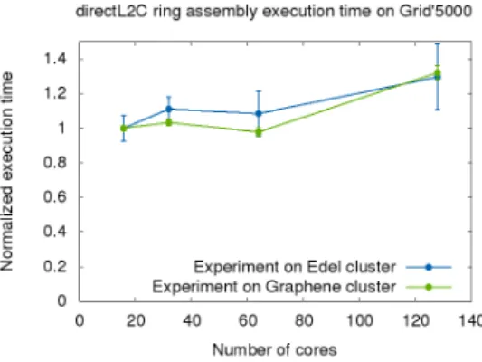
Figure 10: Scalability experiments of the ring assembly implementation on Grid’5000 clusters. Computing time is normalized using the computing time for 16 cores on 1 node.
We have first measured the overhead introduced by our implementation outside of any re-configuration. Contrary to LLCMC++ which introduces zero overhead at runtime, our model requires connexions to be lockable and thus adds a mutex lock for each method call through a port, even when reconfiguration is not occurring. Our measurements indicate that the overhead introduced by our implementation is approximately 5 ns per call through a port. Although this may not be negligible in certain very fine-grain applications, it is negligible for most of HPC applications.
We have also conducted a series of preliminary scalability experiments on Grid’5000 using a simple version of the ring assembly which, starting from a small ring, inserts new computation components until there is one computation component per physical core. Weak scaling results, presented in Figure 10, show that iteration time stays roughly constant when the number of cores increases which shows that our code scales up to 128 cores. Larger experiments are needed to fully validate the scalability of our approach but, baring technical problems and since only local synchronization is ever done, the program should scale.
6
Conclusion and Perspectives
This paper has presented the directMOD model to address the problem of dynamic reconfigura-tion in component models with HPC performance and scalability constraints. We have identified three shortcomings of existing reconfigurable component models which are that centralized re-configuration does not scale, synchronization between rere-configuration components is required for reuse and consistency, and reconfiguration at composite level does not match the actual structure of many HPC applications. directMOD is a component model which addresses these shortcom-ings and which is based on the ideas that reconfiguration shall occur on arbitrary subsets of the
assembly called domains so as to allow any scheme of distributed locking, and that transfor-mations can be plugged on domains at assembly-level so as to allow transformation reuse and composition.
Evaluations of directMOD have been first done through examples based on a Ring Compu-tation and on AMR. They show that it is easy to reuse and to compose generic transformations to program several variants of a given assembly. We also present a C++ implementation of directMOD called directL2C and evaluate its performance through a set of experiments on the Grid’5000 platform. We show that static overhead is very low and that preliminary experiments scale up to 128 cores.
In addition to larger scale experiments, perspectives include extending the model with easier locking mechanisms since currently locking is error-prone and totally up to the programmer, ex-tendint the model with genericity features such as 1-to-n connexions and generic domain adapters so as to avoid the explosion of number of transformations required, and extend the model so that is supports hierarchy to some extent.
7
Acknowledgments
Experiments presented in this paper were carried out using the Grid’5000 experimental testbed, being developed under the INRIA ALADDIN development action with support from CNRS, RE-NATER and several Universities as well as other funding bodies (see https://www.grid5000.fr).
References
[1] Daniel Balouek, Alexandra Carpen Amarie, Ghislain Charrier, Frédéric Desprez, Em-manuel Jeannot, EmEm-manuel Jeanvoine, Adrien Lèbre, David Margery, Nicolas Niclausse, Lucas Nussbaum, Olivier Richard, Christian Pérez, Flavien Quesnel, Cyril Rohr, and Luc Sarzyniec. Adding virtualization capabilities to the Grid’5000 testbed. In IvanI. Ivanov, Marten Sinderen, Frank Leymann, and Tony Shan, editors, Cloud Computing and Services Science, volume 367 of Communications in Computer and Information Science, pages 3–20. Springer International Publishing, 2013.
[2] Ananda Basu, Marius Bozga, and Joseph Sifakis. Modeling Heterogeneous Real-time Com-ponents in BIP. In Proceedings of the Fourth IEEE International Conference on Software Engineering and Formal Methods, SEFM ’06, pages 3–12, Washington, DC, USA, 2006. IEEE Computer Society.
[3] Ananda Shankar Basu. Component-based Modeling of Heterogeneous Real-time Systems in BIP. PhD thesis, Université Joseph Fourier, 2008.
[4] David E Bernholdt, Benjamin A Allan, Robert Armstrong, Felipe Bertrand, Kenneth Chiu, Tamara L Dahlgren, Kostadin Damevski, Wael R Elwasif, Thomas GW Epperly, Madhusud-han Govindaraju, et al. A component architecture for high-performance scientific computing. International Journal of High Performance Computing Applications, 20(2):163–202, 2006. [5] Julien Bigot, Zhengxiong Hou, Christian Pérez, and Vincent Pichon. A low level component
model easing performance portability of hpc applications. Computing, pages 1–16, 2013. [6] Eric Bruneton, Thierry Coupaye, Matthieu Leclercq, Vivien Quéma, and Jean-Bernard
Stefani. The fractal component model and its support in java. Software: Practice and Experience, 36(11-12):1257–1284, 2006.
18 Vincent Lanore, Christian Pérez [7] Jérémy Buisson, Everton Calvacante, Fabien Dagnat, Elena Leroux, and Sébastien Martinez. Coqcots & Pycots: non-stopping components for safe dynamic reconfiguration. In The 17th International ACM Sigsoft Symposium on Component-Based Software Engineering, page 1, Lille, France, June 2014.
[8] T. Bures, P. Hnetynka, and F. Plasil. Sofa 2.0: Balancing advanced features in a hierarchical component model. In Software Engineering Research, Management and Applications, 2006. Fourth International Conference on, pages 40–48, Aug 2006.
[9] Carsten Burstedde, Lucas C. Wilcox, and Omar Ghattas. p4est: Scalable algorithms for parallel adaptive mesh refinement on forests of octrees. SIAM Journal on Scientific Com-puting, 33(3):1103–1133, 2011.
[10] Christian Heinzemann and Steffen Becker. Executing reconfigurations in hierarchical com-ponent architectures. In CBSE, page 3–12, 2013.
[11] Petr Hnětynka and František Plášil. Dynamic reconfiguration and access to services in hierarchical component models. In Proceedings of CBSE 2006, Vasteras, Sweden, LNCS 4063, page 352–359. Springer-Verlag, 2006.
[12] Tobin Isaac, Carsten Burstedde, and Omar Ghattas. Low-cost parallel algorithms for 2: 1 octree balance. In Parallel & Distributed Processing Symposium (IPDPS), 2012 IEEE 26th International, pages 426–437. IEEE, 2012.
[13] A. Langer, J. Lifflander, P. Miller, Kuo-Chuan Pan, L.V. Kale, and P. Ricker. Scalable algorithms for distributed-memory adaptive mesh refinement. In Computer Architecture and High Performance Computing (SBAC-PAD), 2012 IEEE 24th International Symposium on, pages 100–107, Oct 2012.
[14] Peter MacNeice, Kevin M Olson, Clark Mobarry, Rosalinda de Fainchtein, and Charles Packer. Paramesh: A parallel adaptive mesh refinement community toolkit. Computer physics communications, 126(3):330–354, 2000.
[15] André Ribes, Christian Pérez, and Vincent Pichon. On the design of adaptive mesh refine-ment applications based on software components. In 2010 Workshop on Component-Based High Performance Computing (CBHPC 2010), Brussels, Belgium, October 2010.
[16] Jérôme Richard, Vincent Lanore, and Christian Pérez. Evaluating Component Assembly Specialization for 3D FFT, July 2014. PRACE whitepaper.
[17] Romain Teyssier. Cosmological hydrodynamics with adaptive mesh refinement: a new high resolution code called ramses. arXiv preprint astro-ph/0111367, 2001.
[18] François Trahay, Élisabeth Brunet, and Alexandre Denis. An analysis of the impact of multi-threading on communication performance. In CAC 2009: The 9th Workshop on Com-munication Architecture for Clusters, held in conjunction with IPDPS 2009, Rome, Italy, May 2009. IEEE Computer Society Press.
Inovallée