Lire
le début
de la thèse
Chapter IV: Fatigue performances of standard Inconel 718: the influence of material-extrinsic parameters
unloadings that modify the interactions between dislocations and interstitial-solute atoms. Garat [Garat et al.,2008] proposed that the nucleation sites of strain jumps and the intergranular crack initiations are located in the same areas of the material microstructure.
These assumptions could be integrated considering that the evidence of the intergranular propagation features are the result of the environment, and more specifically oxygen.
Oxidation occurs preferentially along the intense deformation bands causing the embrittlement of these zones by oxygen diffusion and oxidation. It has been demonstrated that for dynamic (at the crack tip) and static embrittlement (stress free) the direct intergranular diffusion of oxygen is the dominant process [Woodford,2006]. The most common reactions include gas bubble (CO-CO2) formation, as a result of oxidation of carbon or carbides, and the oxidation of oxide forming impurities or minor alloying elements. These mechanisms induce the formation of localised cavitation that leads to an intergranular propagation, reducing the ability to accommodate stress concentrations at sliding grain boundaries.
Following these considerations, Ter-Ovanessien [Ter-Ovanessian et al.,2008] have investigated the effect of the interstitial species concentrations on the rupture mode. These studies demonstrated that the flow instabilities are controlled by the interstitial content of alloying elements such as carbon, nitrogen and oxygen. The planar slip mechanism is responsible for the intergranular oxidation in Inconel 718: oxygen may react with interstitial carbons brought by dislocation at grain boundaries, forming gas bubbles. On the other hand, the occurrence of the PLC effects is based on strong interactions between dislocations and interstitial carbons: the atoms are localized on the sites where they pin dislocations and the intergranular oxidation is avoided. In such a way, independently of the deformation amplitude, the stress serrations (PLC) lead, systematically, to a transgranular ductile propagation.
These considerations point out the main roles played by the strain rate on the fatigue behaviour. Results have clearly shown the effects associated to the PLC mechanisms which act, mainly, on the stress-strain response, on the inhomogeneity of deformation mechanisms and on the resistance to intergranular cracking assisted by oxidation.
IV
Quantitative analysis of fatigue crack growth by
fractographic investigations
IV.1 Introduction
The microscopical investigations performed on fracture surfaces have shown that fatigue striations can spread, in transgranular fractures, over the major part of the flaw surface. The most interesting quantitative information associated to a fatigue fracture surface is related to striations. The description of fatigue cracks by a quantitative micro-fractography approach offers a potential basis for the reconstitution of the crack growth kinetics. According to previous studies, it is assumed that one striation corresponds to one cycle in ductile materials:
Chapter IV: Fatigue performances of standard Inconel 718: the influence of material-extrinsic parameters
the distance between two striations (i) is related to the instantaneous crack propagation rate da/dN at a given crack length (a). Fracture surfaces, characteristic of post mortem LCF specimens, are investigated using SEM measurements of fatigue striation spacing along the crack propagation direction. Different mechanical approaches and fractographic techniques are implemented for the analysis of the experimental data: the results of the fractographic reconstitutions are presented and directly compared to the crack growth rate published in the literature. The aim of this section is to investigate the crack propagation process. First, a brief review of the process of fatigue striation formation is presented, then, the experimental approaches used for the fractographic reconstitution and their relative results are discussed in detail.
IV.2 Fatigue striations formation
The crack propagation process has been widely studied in the past fifty years with a particular attention to its microstructural aspects. Before focusing on the investigation of the fracture surfaces, it is important to remind the common features of a typical fatigue failure. As shown in Figure IV. 41, the fracture surface exhibits two distinct regions. The cross section area corresponds to the fatigue crack region, whereas the coarse zone at the top of the final catastrophic failure is the remaining cross section that survived to the fatigue damage.
1 mm Initiation Propogation Final Facture 1 mm Initiation Propogation Final Facture
Figure IV. 41 : Typical appearance of a LCF fracture surface of IN718 at 550°C.
Initial cracks are observed close to the outer perimeter of the fatigue specimen: cracks develop with an angle of about 45° over a few microns before propagating perpendicular to the axial longitudinal loading. Higher magnification observations, performed along the crack propagation direction, show the presence of wavy darker and lighter bands that are commonly called “beach marks”. These marks contain thousands of “striations” assumed to be individual steps of crack propagation, with inter-distance that depends on the stress/strain range. Specific researches on the mechanism of fatigue striations were carried out by Laird and Smith and later by Neumann and Pelloux [Pelloux,1970; Neumann,1974]. The authors showed that in a high-strain loading cycle, crack extension is associated to a sliding off mechanism with blunting of the crack tip during loading and consequent re-sharpening upon unloading.
This mechanism, called “plastic blunting”, plays an important role in the damage process relative to the Stage II of the crack propagation. Figure IV. 42 reports a schematic attempt for
Chapter IV: Fatigue performances of standard Inconel 718: the influence of material-extrinsic parameters
representing the different phases of the phenomenon. Under the application of the tensile load, metal plastifies plastically due to the high stress concentration. Plasticity is located along the slip planes of maximum shear stress (b) and crack tip blunts occur under further increase of the tensile load. This mechanisms leads to the displacement of the crack tip (c). Finally, when loading is reversed, the crack tip returns to a sharp configuration through the opening of newly created surfaces. This results in the formation of striation (d and e). Making the assumption that the compression loading is not sufficient to fully annihilate the crack tip blunting, a net crack growth occurs during the subsequent tensile load.
Figure IV. 42 : Plastic blunting process due to fatigue crack propagation in the Stage II mode, considering a vertical stress axis. [McEvily et al.,2010]
This process of fatigue crack growth, via striations formation, leads to the propagation of a fatigue crack on a cycle-by-cycle basis. As reported by Cai [Cai et al.,2001], the crack extension occurs upon each single load cycle as a consequence of cyclic slip occurring at crack tip.
These assumptions are considered in detail for the fractographic investigations of the fatigue surfaces as reported in the next sections.
IV.3 Fatigue striations spacing (FSS) assessment
The relationships between microstructure and engineering properties represent one of the primary goals of this research work. Focusing on fatigue mechanisms, the understanding of the quantitative effects of various microstructural features on crack inititation and propagation is limited by the localized nature of the damage mechanisms. In the previous section, the presence of fatigue striation has been related to transgranular crack propagation, able to inhibit the development of time-dependent mechanisms (generally associated to intergranular propagation).
In addition to these features, a fractographic study of the fatigue surfaces is prone to allow the identification of the failure process history, in particular the description of fatigue crack growth as a function of time and space (distance from the initiation site) [Levaillant et al.,1982].
The first step to the quantitative analysis of fracture profiles is based on the measurement of the fatigue striation spacing. The method, used here, consists in measuring the number (N) of striations intercepting a reference straight line (with length LT) lying along the direction
Chapter IV: Fatigue performances of standard Inconel 718: the influence of material-extrinsic parameters
normal to striations.
In such a way, the average center to center spacing im, between two adjacent striations, is expressed by the following ratio:
im = LT/N Eq. IV. 11
Specimens are placed in the SEM with the plane of fracture accurately perpendicular to the electron beam axis. This configuration is an essential requirement because angular mis-orientations can be a source of significant error [Connors,1994].
The measurements are carried out in a direction normal to the striations orientation, that is essentially grain-dependent (Figure IV. 43(a)). The obtained values must be recalculated by projecting them on the crack propagation direction (CPD) (Figure IV. 43(b)). The random distribution of the parallel striations requires the introduction of a correction factor. Underwood and Starke [Underwood,1979] studied the specific geometrical relations concerning the striation spacing. They observed that when striations are randomly oriented with respect to the direction of propagation, a correction factor (evaluated following the geometrical relationship between the CPD and the fatigue striations orientation) of 2/π is required. In this case, the striation spacing is expressed by:
i = 2/π*im Eq. IV. 12
Figure IV. 43 : Methods of measurement of fatigue striation spacing on fatigue surfaces: (a) measurement normal to striations, (b) measurement normal to macroscopic direction of propagation [Chermant et
al.,1979].
IV.4 Fractographic reconstitution methodology
The fractographic methodology, described above, is applied for the reconstitution of fatigue cracks of failed LCF specimens. In general, one or several cracks grow simultaneously in a direction perpendicular to the loading axis until the complete rupture of the sample occurs. The fracture surface is then assessed by SEM observations.
Measurements are carried out on three specimens, subject to LCF tests under cyclic loading (1 Hz) at different total strain amplitudes (±1%, ±1.2%, and ±0.6%). As illustrated in previous sections, the applications of this type of loading leads to a transgranular fracture characterized by significant striation.
The fracture surface in the region of the predominant crack is characterized by three different zones (Figure IV. 41):
Chapter IV: Fatigue performances of standard Inconel 718: the influence of material-extrinsic parameters
- Stage I: crack initiation and preliminary propagation zone (free of striations);
- Stage II: ductile propagation zone (with striations);
- Stage III: final propagation zone.
The first zone corresponds to the Stage I: fatigue striations are not observed in this zone at least along distance lower than 25-50 µm from the outer surface of the sample (crack initiation site).
These observations are in agreement with the results reported by Jacquelin, for Inconel 718, [Jacquelin,1983] who defined the crack initiation onset as the number of cycles required to obtain a crack length close to the grain size. The standard microstructure, examined for these analyses, shows a small grain size, close to 20 µm, that is in agreement with the extent of crack initiation stage.
The largest part of the fatigue fracture surface corresponds to Stage II of crack propagation, where ductile striations are detected perpendicular to the direction of the loading axis. The striation spacing increases with the advance of the crack length (a). Figure IV. 44 reports a
qualitative comparison of the striation spacing for different crack depths, for a sample loaded
with a total strain amplitude of 1.0%.
Finally, stage III is related to unstable crack growth that is controlled by static modes of failure and is very sensitive to the microstructure, load ratio, and stress state (plane stress or plane strain loading).
Chapter IV: Fatigue performances of standard Inconel 718: the influence of material-extrinsic parameters
Figure IV. 44 : SEM investigation of fracture surfaces at different crack length: a=22,3 µm (A), a=223 µm (B) and a=512,9 µm (C)
Chapter IV: Fatigue performances of standard Inconel 718: the influence of material-extrinsic parameters
Quantitatively, the results of these preliminary analyses are summed up in Figure IV. 45 where (i) is plotted against (a).
Figure IV. 45 : Typical examples of striation spacing as function of the crack length under various LCF conditions (a0=22,3 µm, ac=69 µm and af=680 µm) .
All specimens show a similar behaviour based on three different regimes associated to specific crack length ranges, that can be described as:
1. Stage I where 0 < a < a0: Once initiated, a fatigue microcrack (a0 ≈20 µm) propagates at the surface of the specimens along high shear stress planes. This zone is very limited as compared to the final crack depth. However the crack initiation, followed by a short crack growth stage, (free of fatigue striations) is a very long process which leads to a propagation rate of few Angstroms per cycle [Bathias,1979].
2. Stage II where a0 < a < af : this stage is mainly characterized by the formation of fatigue striations on the fracture surface. Two different zones can be pointed out by a detailed study of the striation spacing:
a) The preliminary fatigue striations where a0 < a < ac: the crack growth follows a nearly constant rate. The presence of this “steady state” may be explained considering two hypothesis:
- Fatigue striations are extremely fine and SEM measurement is not accurate enough to detect such slight variation in striation spacing.
Chapter IV: Fatigue performances of standard Inconel 718: the influence of material-extrinsic parameters
the crack tip is generally small and the associated stress intensity factors do not induce rapid crack propagation.
b) The continuous crack propagation where ac < a < af : the crack propagation continuously increases with the crack length up to the complete fracture of the specimen.
Following these assumptions and as generally admitted we can express the fatigue life as the sum of the initiation fatigue life Ni and the propagation fatigue life NP:
Nf = Ni + NP Eq. III.3
Following the results reported by Oudin [Oudin,2001], the propagation mechanism can be described in two steps:
1. Np1: the number of cycles required to propagate the crack from a0 toac under the effect of a nearly constant crack growth rate (ν).
2. Np2: the number of cycles required to propagate the crack from ac toaf with increasing rate following a specific law.
Np= Np1+Np2 Eq. III.4
The number of cycles corresponding to the regime where crack propagation remains constant is: ν ) ( 0 1 a a N c p − = Eq. III.5
On the other hand, propagation fatigue life can be evaluated considering the striation spacing as an input for the relation proposed by Nedbal [Nedbal et al.,2008]:
∫
⋅ = f c a a p a i i D da N ) ( ) ( 2 Eq. III.6Where af corresponds to the final crack length, ac represents the crack length from which striation spacing starts progressively to increase and D(i) is the ratio between striation spacing (i(a)) and macroscopic crack growth rate (v= da/dN) [D=v/i]
The latter factor reflects the local microscopic processes that take place at the crack tip during the growth of the macroscopic fatigue crack. These phenomena are influenced by the heterogeneous microstructural features and by a continuous redistribution of the externally induced stress and strain fields.
In order to simplify the estimations and referring to results reported by de Matos [de Matos et al.,2005], all integrations are carried out using D=1. In such a way we conclude that the distance between two striations (i) is specifically related to the instantaneous crack growth rate at a given crack depth (a).
Following these assumptions, the numerical integration of the experimental striations spacing curves is based on these assumptions:
Chapter IV: Fatigue performances of standard Inconel 718: the influence of material-extrinsic parameters
- The knowledge of one pair of data (Ni, ai); - D= v/i =1
For each case, the couple of data is derived from the total number of cycles spent under LCF conditions (Nf) and the final crack length af that is assessed on fracture surfaces by SEM investigations.
Calculations provide the number of cycles necessary for crack propagation (Np). As a consequence of these results, fatigue initiation life can be evaluated as the complementary fraction of the fatigue life:
Ni = Nf -NP Eq. IV. 13
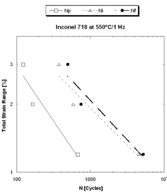
Results are showed in Figure IV. 46 where Ni is related to the number of cycles to failure Nf evaluated by the experimental LCF tests.
The diagram illustrates, for high strain amplitudes, a crack initiation process that represents the major part of the fatigue life, ranging between 75% and 90%. Results are closed to that reported by Jacquelin [Jacquelin,1983] for Inconel 718 LCF tests performed at 20°C.
Figure IV. 46 : Correlation between crack initiation life (Ni) and total fatigue life (Nf)
In agreement with Oudin [Oudin,2001], Ni and Np could be represented as a function of the applied mechanical strain range as reported in Figure IV. 47. For both cases, data follow a power law type that is similar to the Manson-Coffin relationship commonly used to represent LCF data (Nf).
In such a way we can conclude that the initiation fatigue life is slightly improved when the applied strain is lowered, as a consequence of the minimized stress/strain concentrations acting to promote crack initiation.
Chapter IV: Fatigue performances of standard Inconel 718: the influence of material-extrinsic parameters
Figure IV. 47 : Mechanical strain range as function of NP, Ni fraction livesand Nf fatigue life.
IV.5 Crack growth rate assessment
Low cycles fatigue is impacted by a large variety of mechanical and microstructural parameters. As described in the previous section, the fatigue behaviour is based on an extended fatigue crack initiation followed by a rapid propagation mechanism which determines the final fracture. The crack propagation mode determines the crack propagation rates: intergranular propagation (respectively transgranular) is associated to high growth rates (respectively low growth rates).
The propagation behaviour, under cyclic loading, is related to the crack size and to the mechanical behaviour of the damaged material. LCF specimens exhibit one or more prevalent small cracks that are significantly larger than the size of the local zone of plasticity. In this case, the Linear Elastic Fracture Mechanics (LEFM), which characterizes the growth of a linear elastic crack, can not be used, and an elasto-plastic approach is required because plasticity is not restricted in a delimited zone.
The aim of this section is to propose a method for predicting crack growth rate under LCF conditions. This study is based on the partition of the problem into three distinct tasks that can be solved independently:
1. Microstructural analysis of the main crack: the first problem consists in developing a fractographic study of the fatigue surfaces allowing the identification of the failure process history.
2. Calculation of key fracture parameters: once the explicit fractographic analysis is assessed, a failure criterion to evaluate the local crack-tip properties (stress, plasticity,
Chapter IV: Fatigue performances of standard Inconel 718: the influence of material-extrinsic parameters
displacement) is required.
3. Crack propagation rate prediction: once the fracture parameters are available, the final step consists in establishing the relationships between the microstructural investigations and the engineering properties previously evaluated. In such a way, a prediction of the crack propagation rate under various loading conditions (different total strain amplitudes) can be assessed.
Previous sections focused on a detailed analysis of the fracture surfaces based on fatigue striations spacing measurement. The calculation of the key fracture parameters is discussed in the next sections. Finally, a direct comparison of the predicted crack propagation rates with the experimental results published in the literature is presented.
IV.5.A
Relationship between Low Cycle Fatigue properties and crack
growth rates
The Linear Elastic Fracture Mechanics is generally used to predict fatigue life of laboratory fatigue specimens crack propagation tests. The elastic stress intensity factor (∆K) is considered as the key fracture parameters in fatigue crack growth under elastic conditions and when the plastic zone around the crack tip is small compared to the crack length. ∆K reflects the stress field near the crack tip, but also the plasticity occurring in this region.
If the above requirements are not met, the cyclic J-integral, in the frame the Elastic plastic Fracture mechanics (EPFM) may be employed. This approach was introduced in order to evaluate crack growth rate where deep cracks and large plasticity are achieved. This method accounts for the stress intensity field at the crack tip by evaluating the energy dissipated during fracture per unit of newly created fracture surface (strain energy release rate). This is a basic concept of fracture mechanics: the energy required by a crack tip to grow must be equal to the amount of energy dissipated for the creation of new surfaces and for inelastic mechanisms to operate. The J-integral approach provides a better understanding of the physical parameters of fracture for a dynamic crack tip in the case of extended plastic deformation.
From a theoretical point of view, the J-integral, as defined by Rice [Rice,1968], is acceptable only for monotonic loadings. This method does not take into account the effects of the residual plasticity in the case of a cyclic loading applied to an elastic-plastic material. For this reason, Dowling and Begley [Dowling et al.,1976] proposed a correction to the standard approach in order to transform J in ∆J.
This approximated solution assumes that fatigue crack propagation consists in a crack growth within a plastic zone and that the fatigue fracture behaviour of this specific area is similar to that of an LCF sample.
The ∆J expression may be deduced from its original definition, corresponding to a monotonic loading, introducing the total applied strain and stress ranges (∆ε and ∆σ). Following these assumptions, the ∆JCycl integral can be expressed as the sum of an elastic (∆Jel) and a plastic (∆Jpl) components related to the LCF data:
Chapter IV: Fatigue performances of standard Inconel 718: the influence of material-extrinsic parameters
∆JCycl = ∆Jel +∆Jpl Eq. IV. 14
Both terms of the relationship are subsequently examined paying attention to their scientific meaning and physical expression.
Focusing on the linear elastic component (∆Jel), the J integral corresponds to the strain energy rate. When the plane strain conditions and the isothermal test conditions are fullfilled, the J-integral may be expressed as following:
E K Jel 2 ∆ = ∆ Eq. IV. 15
(The modulus of elasticity (E) being deduced from the tensile test carried out at 550° C). The previous equation can be transformed into:
2 2 1 π σ ∆ ⋅ ⋅ ⋅ = ∆ Y a E Jel Eq. IV. 16
Where ∆σ is the applied stress range and Y is a geometrical correction factor, calculated by the approach described above.
The evaluation of this parameter for cylindrical component, such as fatigue specimens, is a complex problem that requires a three-dimensional approach.
According to Yang results [Yang et al.,2006], the evolution of the crack shape may be approximated by an elliptical curve, as reported in Figure IV. 48, where 2b is the major axis and 2a the minor axis of the ellipse. As observed by other authors [Branco et al.,2008], the early propagation is sensitive to the initial crack configuration. For the semi-circular (a/b=1) and elliptical tip (a/b<1) the crack advances more rapidly towards the centre of the specimen than along the free surface. This is due to the maximum stress intensity factor attained at the deepest point of the crack. As a consequence, the crack front tends to become curved and the aspect ratio a/b increases.
R R
Figure IV. 48 : Geometrical configuration of a semi-elliptical crack in a round bar [Yang et al.,2006].
A mathematical correction approach, based on specific finite element analyses, was defined by Yang as a function of the relative crack length, respectively estimated at different locations
Chapter IV: Fatigue performances of standard Inconel 718: the influence of material-extrinsic parameters
on the crack tip:
4 3 2 2 . 11 0 . 12 599 . 0 23 . 1 906 . 0 ⋅ − ⋅ + ⋅ + ⋅ − = D a D a D a D a Y Eq. IV. 17
Where D is the specimen diameter.
In such a way, ∆Jel can be calculated for every point along the crack tip, from the deepest point of the crack and assuming a semi-elliptical geometry.
Similarly to ∆Jel, the plastic component ∆Jpl can be calculated using a reference stress approach that follows the general relationship proposed by Liu [Liu et al.]:
= ∆
∫
∆ p P pl Y a d J εε
σ
π
0 2 2 Eq. IV. 18The integration factor corresponds to a cyclic stress/strain relationship that respects a power hardening law: * 0 n p C
ε
σ
= Eq. IV. 19Where C0 andn* are material dependent constants that can be evaluated from the tensile loading portion of the cyclic hysteresis loop corresponding to each LCF cycle.
Substituting the latter equation in the ∆Jpl relationship, we obtain:
= ∆
∫
∆ p P n p pl Y a C d J εε
ε
π
0 0 2 * 2 Eq. IV. 20 + ∆ ⋅ = ∆ + ) 1 ( ) )( ( 2 * 1 0 2 * n C a Y J n p plε
π
Eq. IV. 21A second form of the relationship can be expressed assuming the hardening equation of the cyclic stress/strain curve as:
(
)
' 2 / ' 2 / kε
p nσ
= ∆ ∆ Eq. IV. 22where k’ and n are material constants that can be related to C0 andn* following Mowbray suggestions [Mowbray et al.,1976]. The authors considered the loading portion of the hysteresis loop equal to the cyclic stress/strain curve when the latter is expanded by a scale factor of 2. In such a way material constants are respectively:
n*= n and C0 =(2)1−n'⋅k' Eq. IV. 23
Based on these considerations, the cyclic J integral is estimated by the following relationship:
[
(
/
2
)
(
2
'
(
)
/(
'
1
)
]
2
2⋅
∆
2+
1 '∆
' 1+
=
∆
J
Y
a
E
−k
n+n
p n Cyclicπ
σ
ε
Eq. IV. 24where K’, n’, ∆εp and∆σp are related to LCF experiments.
Chapter IV: Fatigue performances of standard Inconel 718: the influence of material-extrinsic parameters
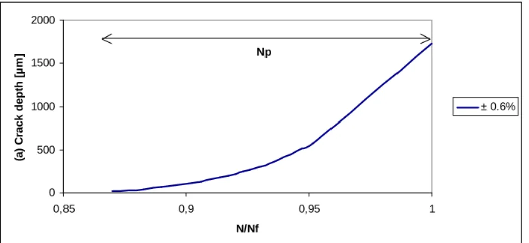
the form of a crack propagation curve that relates the crack length to the number of cycles (Figure IV. 49). The crack depth is measured by SEM investigation as the distance between the crack initiation site and the edge of the fatigue striations zone.
0 500 1000 1500 2000 0,85 0,9 0,95 1 N/Nf (a ) C ra c k d e p th [ µ m ] ± 0.6% Np
Figure IV. 49 : Fatigue crack history reconstitution for a fatigue test carried out with a total strain amplitude of ±0.6 %.
Following the fractographic reconstitution of crack growth with time, a=a(N), and analysing the stress-strain response under LCF conditions associated to each cycle, it is possible to evaluate all the parameters included in the J-integral relationship. In such a way,
∆JCycl is estimated at the crack tip as a function of the increasing crack length (a).
Finally, the J-integral is used to predict the theoretical crack growth rate following the relationship proposed by Sadananda [Sadananda,1984]:
(
)
m CyclE J A dN da ∆ = Eq. IV. 25Where A and m are two constants relative to the material and E is the Young modulus.
Consequently, the crack growth rate curves may be assessed by using the
E
J
Cycl∆
parameter as a Fatigue Crack Growth Rate (FCGR) criterion.The general algorithm, considered for the fractographic reconstitution by the J-integral method, is reported in Figure IV. 50.
Chapter IV: Fatigue performances of standard Inconel 718: the influence of material-extrinsic parameters
Figure IV. 50 : Algorithm for fractographic reconstitution by the J-integral approach.
Chapter IV: Fatigue performances of standard Inconel 718: the influence of material-extrinsic parameters
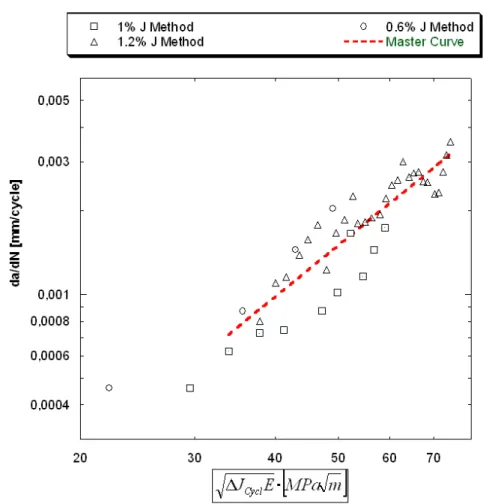
Figure IV. 51 : Crack growth rate reconstitution by striations spacing using the J-integral approach.
The crack growth parameters obtained for the three LCF tests used in this investigation are presented in Table IV. 4. A general Master curve is plotted by the aim to predict the average crack propagation rate for increasing
∆
J
CyclE
parameters.∆εtot A m
± 0.6% 2.36 x 10⁻⁸ 2.27
± 1.0% 1.10 x 10⁻⁶ 1.77
± 1.2% 2.56 x 10⁻⁶ 1.65
Master Curve 8.69 x 10⁻⁷ 1.91
Table IV. 4 : Summary of the crack rate parameters obtained for different applied total strains under LCF conditions.
Chapter IV: Fatigue performances of standard Inconel 718: the influence of material-extrinsic parameters
IV.5.B
Comparison with experimental results
The final step of our investigation consists in a direct benchmarking with the experimental crack growth results, published in the literature [James,1986; Ghonem et al.,1993; Xie et al.,1997] and evaluated on Compact Test (CT) specimens. These reference data are plotted as a function of the stress intensity factor, ∆K evaluated by the Linear Elastic Fracture Mechanics (LEFM). In such a way test performed with a load control at temperatures closed or equal to 550°C have been selected even if the test parameters (such as frequency (f) and stress ratio (R)) differ from our standard LCF tests. Figure IV. 52 compares the literature data with the crack growth rates predicted by a J-integral approach.
Figure IV. 52 : Comparison between the experimental crack growth rates, evaluated by a fractographic reconstitution of LCF tests, and the literature data obtained on C.T specimens.
Compared with elastic-plastic crack growth experimental data, this alternative approach shows good correspondence: the scatter is limited and the results are satisfactorily similar. The crack growth constants associated to the experimental results reported in literature, are listed in Table IV. 5.
Chapter IV: Fatigue performances of standard Inconel 718: the influence of material-extrinsic parameters Source T [°C] A m
( )
( )
J E MPa m m MPa K for dN da dN da Cycl Method J 50 50 = ∆ = ∆ − [James,1986] 538 1.82 x 10⁻⁷ 2.17 0.6 [Ghonem et al.,1993] 538 6.42 x 10⁻⁹ 3,19 1.1 [Xie et al.,1997] 550 3.2 x 10⁻⁸ 2.58 0.5 J Method-Master Curve 550 8.69 x 10⁻⁷ 1.91 1.0Table IV. 5 : Summary of the crack rate parameters associated to the experimental FCGR tests reported in literature.
Furthermore, the Table reports a ratio between the predicted crack propagation rate obtained through standard CT specimens, available in literature, and our crack growth rate obtained by fractographic analysis of LCF specimens for a value of ∆K≈
∆
J
CyclE
equal to 50MPa m.The values assumed by this ratio, ranging between 0.5 and 1.1, justifies the validity of the theoretical model and points out a close link between the LCF properties and the FCG behaviour. The J-integral approach provides a good correlation between crack growth and crack length, in the case of extended plastic deformation.
However, the robustness of the method has to be assessed on other test data obtained under various loading histories (as well as frequency, strain, stress and temperature) in order to precisely determine where it can be generalized.
As described above, fatigue crack growth produces, on fracture surfaces, some striations that can help in understanding the location of the crack origin and the directionality of propagation. The practical approach proposed for the fractographic reconstitution of the fatigue crack growth provides complementary information to that obtained from classical LCF tests, reducing the costs directly related to the specimens preparation and to the realization of extensive FCG test campaigns.
Chapter IV: Fatigue performances of standard Inconel 718: the influence of material-extrinsic parameters
V
Conclusion
In the preliminary part of this chapter, attention is given to the cyclic behaviour of Inconel 718 under various LCF test conditions. A cyclic behaviour model is proposed in order to predict the stress-strain response typical of extrusion dies. The considered model is a strain rate independent version of the non-linear kinematic hardening model proposed by Chaboche [Chaboche et al.,1994]. The constitutive equations are integrated in a FEA code to simulate the evolution of the stress-strain state in an experimental extrusion die. The good agreement between the simulations and the experimental data, obtained by direct measurements on production presses, indicates that the Dynamic Modelling provides satisfactory estimates of the evolution of the loading state (stress-strain) in the tool
Attempts were made to compare the simulated results using the material dynamic model used by Hydro. Comparisons show that the dynamic model is able to predict the evolution of loading state cycle by cycle, taking into consideration the different transient phenomena (such as softening) which are not assess by the traditional method. In such a way, the so called “Dynamic Material Modelling” may represent an interesting alternative to high risk and cost trial and error approach for design of Ni-base superalloy dies.
In the second part of the chapter, the fatigue life assessment of Inconel 718 at elevated temperature (550°C) is presented. Two LCF fatigue signals are considered. A cyclic symmetric waveform (1 Hz) is considered as a preliminary approach to the fatigue life behaviour, then, a trapezoidal signal (150_20 s), characterised by holding times in tension and compression, is used to reproduce the die loading state during the extrusion cycle. Fatigue life curves are plotted using the so-called Manson-Coffin relationship, identifying the relation between inelastic strain and fatigue life.
In both cases, a similar cyclic behaviour is detected: material exhibits a continuous softening from the very first cycles. This mechanism results in a continuous stress decrease coupled to an inelastic strain enhancement.
Comparisons between Inconel 718 and the traditional Hot Work tool steels are proposed, for similar LCF tests conditions, assessing the better performances of the superalloy. Differences in terms of stress-strain response are identified: after a preliminary stress decrease, steels show a continuous linear softening regime, while Inconel 718 exhibits an apparent stability of the stress amplitude (pseudo-stabilized stage). It can be concluded that as a better cyclic behaviour is obtained, the life time of an extrusion die, using Inconel 718 as a bulk material, will be longer that that of traditional steel dies.
The effects of different mechanical parameters on the fatigue life behaviour of Inconel 718 are investigated in details. The following conclusions can be derived:
- Effect of Holding Time
Chapter IV: Fatigue performances of standard Inconel 718: the influence of material-extrinsic parameters
decrease of the fatigue life by 33% as compared to that obtained with a cyclic signal (1 Hz). This effect may be explained by the increase of the plastic strain amplitude at half life due to the stress relaxation during holding time Investigating effect of holding time at maximum strain is corresponding to the influence of extrusion cycle length. The die will be submitted to maximum loading as soon as the pressure ramp-up starts and will be until billet extrusion is completed. Among parameters affecting cycle duration, we especially shall consider the actual billet length, the ramp-up time (time to reach max press force) and deceleration time (extrusion speed decrease to cycle stop). These parameters are prone to fluctuate for process control reasons and it is commonly accepted that overall cycles are spanning from 45s and 300s. Being aware of cycle length effect on die life may be critical and selecting both die design parameters and extrusion process control. Three different wave-forms were considered to cover the 45-300 s interval (holding time 45 s, 150 s and 300 s). The increase of the exposure time at maximal strain does not further decrease the fatigue life. As a matter of fact, material exhibits a rapid stress decrease during the first 40 seconds of the steady time, followed by a linear relaxation which has limited effects on the inelastic strain. It is then understood that over 40s of extrusion cycle and within 300s. no large die life difference should observed which allow to conclude that Inconel 718 die may not need design changes due to selected cycle duration selected by press team.
- Strain rate
At 550°C, low cycle fatigue behaviour is strongly influenced by the strain rate. A strain rate of5⋅10−3s , defined as the average die loading rate assessed at the press, has been −1
adopted as the reference value for the extrusion cycle simulation. LCF tests carried out at this strain rate (5⋅10−3s ) exhibit, on stable hysteresis stress-strain loops, stress −1
instabilities associated to the Portevin-Le Chatelier effects (PLC). In other words, changes in fatigue behaviour are due to the interaction of cyclic deformation and time dependent processes that act concomitantly on the stress-strain response, on the heterogeneity of the deformation mechanisms and on the resistance to oxidation- assisted intergranular cracking. In terms of microstructural evolution, the reduction in fatigue life, at low strain rate, is attributed to the acceleration of fatigue initiation, associated to the increased density of planar slips, and to the change of crack propagation from a transgranular to a mixed mode type.
Following these assumptions, it can be concluded that strain rate and holding time have a significant impact on fatigue life, although any effects are detected on the cyclic behaviour at 550°C. Generally speaking, we can interpret these effects as time-dependent phenomena: the application of a holding time or the variation of strain rate
act on the frequency of the fatigue cycle. Slow cycles enhance the interaction between mechanical loading and environmental effects producing mixed or intergranular brittle fractures. In such a way, the total cyclic time affects the deformation mechanisms, which have a direct impact on the fatigue behaviour. Results reported in this chapter
Chapter IV: Fatigue performances of standard Inconel 718: the influence of material-extrinsic parameters
demonstrate that the total cycle time, as well as the loading frequency, can influence the fatigue life of Inconel 718, contributing to its final fracture mode. These assumption are confirmed by previous studies [Ghonem et al.,1993] focused on crack growth rate, as reported in Figure IV. 53. At frequencies below 0.01 Hz the fracture behaviour becomes “Time–dependent” and the fatigue crack growth rate increases as cyclic frequencies decrease. On the other hand, for frequencies above 10 Hz, the material becomes totally “Cycle-dependent” leading to crack growth rates that are independent of frequency. Different mechanisms of crack growth are associated to each regime. Transgranular propagation, with striation formation, is generally observed in the cycle-dependent regime, whereas intergranular crack growth is the predominant mechanism observed in the time-dependent regime.
Figure IV. 53 : Effects of cyclic frequency on alloy 718 tested at high temperature [Ghonem et al.,1993].
The reference extrusion cycle, determined by a holding time of 150 seconds at 550°C (1/T=0.0012 K-1), could be defined as an equivalent frequency of 0.005 Hz. These data, opportunely associated to the diagram reported in figure, defines the aluminium extrusion as a process affected by an interaction between a mixed and a time dependent damaging mode. Holding time and strain rate are two mechanical parameters that increase the risks associated to these time dependent phenomena. In particular, the strain rate which corresponds to the die loading rate has an important influence on the mechanical performances of the tools. Results suggest that an increase of the loading rate may improve the extrusion die life limiting the material softening and delaying the fatigue crack nucleation.
Practically at the press, this would mean that it could be of interest to discuss the possibility for the hydraulic piloted ram to have a higher loading rate capacity. Clearly some press construction limitations are expected to be met. On the other hand, a
Chapter IV: Fatigue performances of standard Inconel 718: the influence of material-extrinsic parameters
reduction of this loading rate (excessive reduction of die loading from 5⋅10−3s to −1
1 4
10
5⋅ − s ) may lead to negative change of die life (die life reduction by a factor of 3) −
and shall consequently brought to attention to extrusion managers using Inconel 718 dies.
- Fatigue crack growth
A fractographic reconstitution of the fatigue crack growth is proposed in the last part of the chapter. The fracture surface examination based on the classical fatigue striation counting method is used to determine the crack growth rate as a function of the crack length. This approach supports the applicability of the empiric relationship between macroscopic crack growth rate and striations spacing, as established by previous experiments [Levaillant et al.,1982; Oudin,2001; de Matos et al.,2005].
The crack growth rate assessment is achieved by the use of the cyclic J-integral that takes into consideration the elastic and inelastic effects at crack tip. The obtained crack growth curves are compared to data for Inconel 718 data extracted from the literature. The fractographic reconstitution method is proved to be efficient for the reconstitution of the crack kinetics history providing growth laws similar to that proposed by Paris. Finally, the life of a LCF sample or an extrusion die is composed of a crack initiation and a crack propagation time. The above method is used to estimate the extension of the two regimes. Comparable results are observed for different strain amplitudes, showing that crack initiation governs the fatigue life of Inconel 718, ranging between 75-80% of the total life.
This alternative approach provides complementary information to that obtained from classical fatigue tests, reducing the costs directly related to the CT specimens preparation and to the realization of extensive FCG test campaigns.
All these assumptions represent a support for the design of alternative Inconel 718 thermal treatments, as it will be described in Chapter V. The optimisation of the material microstructure must be carried out in order to contain the time dependent damage associated to the extrusion cycle (such as the material relaxation during the holding time at maximal strain). Finally, the prevalence of the crack initiation time over the crack propagation requires a tailored microstructure able to further delay the risks of crack initiation associated to the localisation of the plastic strain in specific areas, as well as in the hot spots of an extrusion die.
Chapter IV: Fatigue performances of standard Inconel 718: the influence of material-extrinsic parameters
VI
References
[Bathias,1979] Bathias, C. "Endommagement par sollicitation cyclique". Dislocations et déformation plastique. Ed.Diffusion: 375-382 (1979).
[Bergstrom et al.,2006] Bergstrom, J. and Rézaï-Aria, F. "High temperature fatigue of tool
steels". TOOL 06 - 7th International tooling conference, Torino (Italy): 545-554
(2006).
[Branco et al.,2008] Branco, R. and Antunes, F. V. "Finite element modelling and analysis of crack shape evolution in mode-I fatigue Middle Cracked Tension specimens."
Engineering Fracture Mechanics 75(10): pp. 3020-3037, (2008).
[Cai et al.,2001] Cai, H. and McEvily, A. J. "On striations and fatigue crack growth in 1018 steel." Materials Science and Engineering A 314(1-2): pp. 86-89, (2001).
[Chaboche et al.,1994] Chaboche, J.-L. and Lemaitre, J. "Mechanics of solid materials", Cambridge University Press, p., (1994).
[Chermant et al.,1979] Chermant, J. L. and Coster, M. "Quantitative fractography." Journal
of Materials Science 14(3): pp. 509-534, (1979).
[Chihab,2004] Chihab, K. "On the apparent strain rate sensitivity of Portevin - Le Chatelier effect." Annales De Chimie-Science Des Materiaux 29(5): pp. 15-23, (2004).
[Clavel et al.,1975] Clavel, M., Fournier, D. and Pineau, A. "Plastic zone sizes in fatigued specimens of Inco 718." Metallurgical Transactions a-Physical Metallurgy and
Materials Science 6(12): pp. 2305-2307, (1975).
[Clavel et al.,1982] Clavel, M. and Pineau, A. "Fatigue behaviour of two Nickel base alloys I: Experimental results on Low-Cycle fatigue crack propagation and substructures."
Materials Science and Engineering 55(2): pp. 157-171, (1982).
[Connors,1994] Connors, W. C. "Fatigue striation spacing analysis." Materials
Characterization 33(3): pp. 245-253, (1994).
[de Matos et al.,2005] de Matos, P. F. P., Moreira, P. M. G. P., Nedbal, I. and de Castro, P. M. S. T. "Reconstitution of fatigue crack growth in Al-alloy 2024-T3 open-hole specimens using microfractographic techniques." Engineering Fracture Mechanics 72(14): pp. 2232-2246, (2005).
[Delagnes,1998] Delagnes, D. "Comportement et tenue en fatigue isotherme d'aciers à outils
Z 38 CDV5 autour de la transition fatigue oligocyclique endurance". PhD Thesis,
Ecole des Mines de Paris (1998).
[Dowling et al.,1976] Dowling, N. E. and Begley, N. A. "Fatigue crack growth during gross plasticity and J- integral". Mechanics of Crack Growth. ASTM: 82-103 (1976).
[Fiétier et al.,2009] Fiétier, N., Krähenbühl, Y. and Vialard, M. "New methods for the fast simulations of the extrusion process of hot metals." Journal of Materials Processing
Technology 209(5): pp. 2244-2259, (2009).
[Fournier et al.,1977] Fournier, D. and Pineau, A. "Low fatigue cycle behaviour of Inconel 718 at 293 K and 823 K." Metallurgical Transactions a-Physical Metallurgy and
Materials Science 8(7): pp. 1095-1105, (1977).
[Fournier et al.,2001] Fournier, L., Delafosse, D. and Magnin, T. "Oxidation induced intergranular cracking and Portevin-Le Chatelier effect in nickel base superalloy 718."
Materials Science and Engineering A 316(1-2): pp. 166-173, (2001).
[Garat et al.,2008] Garat, V., Cloue, J. M., Poquillon, D. and Andrieu, E. "Influence of Portevin-Le Chatelier effect on rupture mode of alloy 718 specimens." Journal of
Nuclear Materials 375(1): pp. 95-101, (2008).
Chapter IV: Fatigue performances of standard Inconel 718: the influence of material-extrinsic parameters
fatigue -crack growth in alloy 718-Part 1: effects of mechanical variables." Fatigue &
Fracture of Engineering Materials & Structures 16(5): pp. 565-576, (1993).
[Hong et al.,2005] Hong, S. G. and Lee, S. "Mechanism of dynamic strain aging and characterization of its effect on the low-cycle fatigue behavior in type 316L stainless steel." Journal of Nuclear Materials 340(2-3): pp. 307-314, (2005).
[Jacquelin,1983] Jacquelin, B. "Amorçage des fissures en fatigue oligocyclique sous
chargement multiaxial". PhD Thesis, Ecoles des Mines de Paris (1983).
[James,1986] James, L. A. "The effect of grain size upon the fatigue-crack propagation behaviour of alloy 718 under hold-time cycling at elevated temperature." Engineering
Fracture Mechanics 25(3): pp. 305-314, (1986).
[Kalluri et al.,2004] Kalluri, S., Rao, K. B. S., Halford, G. and McGaw, M. A. "Deformation
and damage mechanisms in Inconel 718 superalloy". Superalloys 718, 625, 706 and
Various Derivatives, E.A Loria (2004).
[Kirman et al.,1970] Kirman, I. and Warrington, D. "The precipitation of Ni3Nb phases in a Ni−Fe−Cr−Nb alloy." Metallurgical and Materials Transactions B 1(10): pp. 2667-2675, (1970).
[Krumphals et al.,2010] Krumphals, F., Wlanis, T., Sievert, R., Wieser, V. and Sommitsch, C. "Damage analysis of extrusion tools made from the austenitic hot work tool steel Böhler W750." Computational Materials Science In Press, Corrected Proof: pp., (2010).
[Lemaitre et al.,1987] Lemaitre, J., Benallal, A., Ben Cheikh, A., Billardon, R., Dufailly, J., Feng, L., Florez, J., Gautherin, M. T., Geymonat, G., Lienard, C., Marquis, D., Mertz, D. and Moret-Bailly, L. "Formulaire de caractéristiques mécaniques de matériaux/
Handbooklet of mechanical characteristics of materials". C. N. d. l. R. Scientifique
(1987).
[Levaillant et al.,1982] Levaillant, C. and Pineau, A. "Assessment of high-temperature low cycle fatigue life of austenitic stainless steels by using intergranular damage as a correlating parameter." Low cycle fatigue and life prediction ASTM STP 770: pp. 169-183, (1982).
[Liu et al.] Liu, J., Yuan, H. and Liao, R. "Prediction of fatigue crack growth and residual stress relaxations in shot-peened material." Materials Science and Engineering: A In Press, Accepted Manuscript: pp.,
[Mannan,1993] Mannan, S. L. "Role of dynamic strain-aging in low-cycle fatigue." Bulletin
of Materials Science 16(6): pp. 561-582, (1993).
[McEvily et al.,2010] McEvily, A. J. and Matsunaga, H. "On fatigue striations." Transaction
B: Mechanical Engineering 17(1): pp. 75-82, (2010).
[Mebarki,2003] Mebarki, N. "Relation microstructure - propriétés mécaniques d'aciers
martensitiques revenus destinés aux outillages de mise en forme d'alliages légers.".
PhD Thesis, Ecole des Mines de Paris (2003).
[Mowbray et al.,1976] Mowbray and D, F. "Derivation of a low-cycle fatigue relationship employing the J-integral approach to crack growth", American Society for Testing and Materials, p. 14, (1976).
[Nedbal et al.,2008] Nedbal, I., Lauschmann, H., Siegl, J. and Kunz, J. "Fractographic reconstitution of fatigue crack history - Part II." Fatigue & Fracture of Engineering
Materials & Structures 31(2): pp. 177-183, (2008).
[Neumann,1974] Neumann, P. "New experiments concerning the slip process at propagating fatigue cracks." Acta Metallurgica 22: pp. 1155-1165, (1974).
[Oudin,2001] Oudin, A. "Thermo-Mechanical Fatigue of Hot Work Tool Steels ". PhD Thesis, Ecole Nationale Superieure des Mines de Paris (2001).
Chapter IV: Fatigue performances of standard Inconel 718: the influence of material-extrinsic parameters
developments". Unpublished Work, Hydro Aluminium PTTC (2010).
[Pelloux,1970] Pelloux, R. M. N. "Crack extension by alternating shear." Engineering
Fracture Mechanics 1: pp. 697-704, (1970).
[Ponnelle,2001] Ponnelle, S. "Propagation des fissures par fatigue à haute température dans
l'Inconel 718: effets de microstructure et de chargements complexes". PhD Thesis,
Ecole des Mines de Paris (2001).
[Rice,1968] Rice, J. R. "A path independent integral and the approximate analysis of strain concentration by notches and cracks." Journal of Applied Mechanics 35: pp. 379-386, (1968).
[Sadananda,1984] Sadananda, K. "Crack propagation under creep and fatigue." Nuclear
Engineering and Design 83(3): pp. 303-323, (1984).
[Ter-Ovanessian et al.,2008] Ter-Ovanessian, B., Deleume, J., Cloue, J. M. and Andrieu, E. "Influence of interstitials content on the sensitivity of alloy 718 to oxidation assisted intergranular fracture." High Temperature Corrosion and Protection of Materials 7,
Pts 1 and 2 595-598: pp. 951-958, (2008).
[Underwood,1979] Underwood, E. E. "Quantification of microstructures by stereological analysis." Journal of Histochemistry & Cytochemistry 27(11): pp. 1536-1537, (1979). [Valsan et al.,1994] Valsan, M., Sastry, D. H., Rao, K. B. S. and Mannan, S. L. "Effect of
strain rate on the High-Temperature Low-Cycle Fatigue properties of a Nimonic PE-16 Superalloy." Metallurgical and Materials Transactions a-Physical Metallurgy and
Materials Science 25(1): pp. 159-171, (1994).
[Velay,2003] Velay, V. "Modélisation du comportement cyclique et de la durée de vie
d'aciers à outils martensitiques". PhD Thesis, Ecole des Mines de Paris (2003).
[Woodford,2006] Woodford, D. A. "Gas phase embrittlement and time dependent cracking of nickel based superalloys." Energy Materials: Materials Science and Engineering
for Energy Systems 1: pp. 59-79, (2006).
[Xie et al.,1997] Xie, J. Z., Shen, Z. M. and Hou, J. Y. "Fatigue Crack growth behaviours in
alloy 718 at high temperature". Superalloys 718, 625, 706 and Various derivatives
(1997).
[Yang et al.,2006] Yang, F., Kuang, Z. and Shlyannikov, V. N. "Fatigue crack growth for straight-fronted edge crack in a round bar." International Journal of Fatigue 28(4): pp. 431-437, (2006).
Chapter V: Relationships between tailored microstructure and fatigue life of Inconel 718
Chapter V
Relationships between tailored
microstructure and fatigue life of
Inconel 718
‘’ Les sentiments sont des métaux. Il importe d'en connaître la densité. Il
importe également d'en connaître la température de fusion ‘’
Chapter V: Relationships between tailored microstructure and fatigue behaviour
Chapter V – Relationships between tailored microstructure
and fatigue life
I Introduction
“The heat treatment of nickel base alloys is an art”[Sims et al.,1972]
Alternative heat treatments, in addition to the standard procedure, have been proposed in chapter III where their mechanical properties have been assessed by tensile tests. Each modified thermal treatment is defined by a series of parameters (time, temperature, cooling rates), associated to the various steps included in the process (solution annealing, quenching and ageing). The choice of these parameters is related to a detailed study of the correlation between microstructure and mechanical properties. This investigation is based on the understanding and modelling of the various steps of the heat treatment process, taking into account the evolution of the so-called material-intrinsic parameters that are the grain structure and the morphology and content of precipitates (δ, γ’ and γ”). This approach may lead to a better control of the heat treatment in order to optimize the alloy microstructure and adapt Inconel 718 to the specific conditions imposed by the extrusion process.
Finally, the microstructure and fatigue properties, resulting from the modified heat treatments, will be discussed providing specific recommendations for the service conditions.
I
Structural characterization of heat treated Inconel 718
I.1
Cooling rate effects
Solution treatment is generally followed by quenching prone to maintain, at room temperature, the super-saturated solid solution. Different cooling methods may be used Minimum hardness is obtained by cooling rapidly from the annealing temperature in order to avoid the precipitation of strengthening phases. Loier [Loier et al.,1984] studied the effects of the cooling rate on the microstructural and mechanical effects of Inconel 718. The authors showed that each cooling method may be characterized by an instantaneous cooling rate,
defined as V700 ( t Ta ∆ − = 700
V700 ) which typically varies from 50 to 105 °C/h.
Figure V. 1 shows the impact of the cooling rate on the material hardness after quenching at 950°C. It is noticeable that harness, in the aged condition, does not exhibit a variation as a function of the adopted quenching method. In general, when V700 is higher than 0.5 °C/s–1,
Chapter V: Relationships between tailored microstructure and fatigue behaviour
the material is not affected by the cooling rate. The same assumptions could be made for the mechanical performances at room temperature (Figure V. 2). The tensile properties of Inconel 718 are insensitive to the cooling rate, after annealing, when V700 is higher or equal to 0.25 °C s –1. 150 200 250 300 350 400
1,0E-02 1,0E-01 1,0E+00 1,0E+01 1,0E+02
Cooling Rate [°C/s] H a rd n e s s [ H V ] Loier Data
Figure V. 1 : Variation in Vickers hardness with quenching rate for Inconel 718, annealed at 950°C, based on Loier [Loier et al.,1984] data.
1000 1100 1200 1300 1400
1,0E-01 1,0E+00 1,0E+01 1,0E+02 1,0E+03 1,0E+04
Cooling Rate [°C/s]
[M
P
a
]
U.T.S [Loier] Y.S [Loier]
Figure V. 2 : Variation in the mechanical properties four double aged Inconel 718 with the initial quenching rate, based on Loier [Loier et al.,1984] data.
The experimental results reported by Slama [Slama et al.,1997], associated to the continuous cooling rate diagram reported in Figure V. 3, complete the study on the effect of the cooling rate in Inconel 718, with a particular attention to the structural transformations. At first sight, we can deduce that for cooling rate higher than 100°C/s–1 the alloy retains an austenitic microstructure.
Chapter V: Relationships between tailored microstructure and fatigue behaviour
Figure V. 3 : Continuous Cooling (C.C.T) diagram for Inconel 718 [Slama et al.,1997].
However, for 5 ≤V700< 100°C/s–1, the delta (δ) phase precipitation is identified. In these conditions the hardness of the quenched material is constant. Finally when the cooling rate is slowest than 5 °C/s–1 an additional precipitation of the strengthening phases (γ’/γ”) takes place leading to a progressive hardening effect.
The quenching rate could be experimentally optimised using a wide range of technological equipments. However, for heavy sections, the cooling rate can change along the profile as a function of the shape and the local thickness. For these reasons, it is recommended to use limited quenching rate so as to reduce the residual stresses which induce early fatigue crack initiations.
The common cooling conditions, for Inconel 718, include:
- water quenching with V700 > 28 °C s-l;
- oil quenching with V700 ~ 8 °C s-l;
- air cooling with V700 ~ 1.25 °C s-l.
To conclude, the common quenching methods offer cooling rates which induce similar structural transformations in the material and equal resulting mechanical properties. As a result, the cooling rate will not be considered in the study of thermal treatment procedure and no further test will be performed to complete literature results.
Chapter V: Relationships between tailored microstructure and fatigue behaviour
I.2
Structural evolution of Inconel 718 during heating process
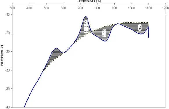
The microstructural optimisation of the alloy and the desired high temperature properties require multi-stage heat treatments that lead to the nucleation or dissolution of secondary phases. Differential thermal analyse (DTA) has been used as an indirect method for examining the characteristic temperatures and the nature of phase transformations in Inconel 718. A heating rate of 10°C/min has been applied in order to ensure thermodynamic equilibrium so that the observed temperature is as close as possible to the “true” reaction temperature. Figure V. 4 reports the DTA thermogram established for Inconel 718 in the “as received” conditions (rolled at 980°C). The onset of any reaction may be defined at the temperature at which the DTA curve deviates from the base line (dotted line). The general profile of this thermogram is in agreement with those reported in literature [Cao W.D Kennedy R.L,1991; Slama,1993].Figure V. 4 : D.T.A analyse on continuous heating of the “as received” Inconel 718.
A preliminary exothermic peak is noticed for temperature ranging between 650°C and 740°C and is associated to a simultaneous precipitation of δ, γ’ and γ” phases. However, it is difficult to separate the domains of precipitation of the three different phases. In general, at 700°C the coherent precipitation of γ”, coupled with the formation of a small amount of γ’, prevails.
An endothermic peak is detected in the range between 760-910°C corresponding to the solvus of the coherent γ’ and γ” phases.
A second endothermic peak in the range 920-1060°C is related to the dissolution of the delta precipitates. Beyond, the FCC solid solution is free of precipitates. In agreement with
Chapter V: Relationships between tailored microstructure and fatigue behaviour
these assumptions, two types of thermal treatments generally used for Inconel 718, can be defined as a function of the solution annealing process:
- Sub-solvus solution annealing: performed at a temperature below the delta solvus.
- Super-solvus solution annealing: performed at a temperature above the delta solvus.
The sub-solvus treatment retains the small grain size (10-12 ASTM) provided by the thermo-mechanical processing of the alloy, holding a certain amount of delta phase within the microstructure. Conversely, the super-solvus treatment may induce an over-growth of the grains. This microstructural evolution depends on the chemical homogeneity of the alloy and on the energy stored through out the entire thermo-mechanical processing. In this case, the enhanced dissolution of delta phase further promotes the precipitation of the strengthening phases γ’ and γ” due to the high availability of Nb within the matrix. Conversely, the largest grain size decreases the strength and fatigue resistance of the alloy. The application of the super-solvus treatment to wrought nickel based alloys requires a detailed understanding of the thermo-mechanical and metallurgical history of the alloy in order to avoid localised grain growth and heterogeneities in mechanical properties.
The effects of the solution annealing on the microstructural features of the alloy (delta phase and grain structure evolution) will be discussed in the next section.
I.3
Delta phase and grain structure evolution
The δ precipitates play an important role in controlling the grain size of Inconel 718. However, a high volume content of this phase, capturing niobium, causes a lower Nb content within the matrix and limits γ” precipitation. As a consequence, the microstructure and the mechanical properties could be significantly affected by the variation of the δ phase volume fractions. Desvallées [Desvallées et al.,1994] showed that an increased presence of delta phase has a detrimental effect on yield strength (10% of reduction as compared to a standard Inconel 718 grade) because it induces a lack of γ”.
Considering these assumptions, the study of the dissolution kinetics of δ precipitates as function of time and temperature, is extremely important to evaluate the microstructure development during the heat treatment process. In such a way, various solution annealing experiments have been carried out on specimens cut and machined to 15 mm diameter and 10 mm height. After annealing for 1 h, all specimens have been air quenched and prepared for SEM investigations. Figure V. 5 exhibits the microstructural evolution in Inconel 718 after solution treatment at 924, 955, 990, 1010 and 1030°C. It is important to point out that these temperatures are in the range defined by the ASTM B637 specification.
The change of the volume fraction of stable phases, as a function of the temperature, could be addressed by a specific 2D image analyse. Figure V. 6 shows the calculated surface fraction of delta phase for different annealing temperatures. Significant δ phase precipitation results from the lower solution temperatures of 924°C and 955°C because of the high equilibrium content of δ
Chapter V: Relationships between tailored microstructure and fatigue behaviour
phase at these temperatures. Limited changes in δ phase structure are noticed at 975°C , whereas at 990°C a partial precipitates dissolution occurs. A certain amount of delta phase still exists at 1010°C, while the dissolution process finishes at 1050°C giving an austenitic microstructure free of precipitates.

![Figure IV. 53 : Effects of cyclic frequency on alloy 718 tested at high temperature [Ghonem et al.,1993]](https://thumb-eu.123doks.com/thumbv2/123doknet/3670234.108614/22.892.180.692.394.756/figure-effects-cyclic-frequency-alloy-tested-temperature-ghonem.webp)
![Figure V. 1 : Variation in Vickers hardness with quenching rate for Inconel 718, annealed at 950°C, based on Loier [Loier et al.,1984] data](https://thumb-eu.123doks.com/thumbv2/123doknet/3670234.108614/31.892.170.756.228.496/figure-variation-vickers-hardness-quenching-inconel-annealed-loier.webp)

![Figure V. 8 : Schematic representation of dissolution and fracture process of δ phase in Inconel 718 [Cai et al.,2007]](https://thumb-eu.123doks.com/thumbv2/123doknet/3670234.108614/38.892.146.775.422.571/figure-schematic-representation-dissolution-fracture-process-phase-inconel.webp)
