HAL Id: tel-03011390
https://hal.univ-lorraine.fr/tel-03011390
Submitted on 18 Nov 2020
HAL is a multi-disciplinary open access
archive for the deposit and dissemination of
sci-entific research documents, whether they are
pub-lished or not. The documents may come from
teaching and research institutions in France or
abroad, or from public or private research centers.
L’archive ouverte pluridisciplinaire HAL, est
destinée au dépôt et à la diffusion de documents
scientifiques de niveau recherche, publiés ou non,
émanant des établissements d’enseignement et de
recherche français ou étrangers, des laboratoires
publics ou privés.
Control of a Traction/Charging Structure for a Hybrid
Electric Vehicle
Saeid Aghaei Hashjin
To cite this version:
Saeid Aghaei Hashjin. Control of a Traction/Charging Structure for a Hybrid Electric Vehicle. Electric
power. Université de Lorraine, 2020. English. �NNT : 2020LORR0117�. �tel-03011390�
AVERTISSEMENT
Ce document est le fruit d'un long travail approuvé par le jury de
soutenance et mis à disposition de l'ensemble de la
communauté universitaire élargie.
Il est soumis à la propriété intellectuelle de l'auteur. Ceci
implique une obligation de citation et de référencement lors de
l’utilisation de ce document.
D'autre part, toute contrefaçon, plagiat, reproduction illicite
encourt une poursuite pénale.
Contact : [email protected]
LIENS
Code de la Propriété Intellectuelle. articles L 122. 4
Code de la Propriété Intellectuelle. articles L 335.2- L 335.10
http://www.cfcopies.com/V2/leg/leg_droi.php
Université de Lorraine : GREEN
Ecole Doctorale : Informatique Automatique Electrotechnique Electronique Mathématiques Commission de mention : Electrotechnique Electronique
Thèse
présentée en vue de l’obtention du titre de
Docteur de l’Université de Lorraine
Spécialité : Génie électrique
par
Saeid AGHAEI HASHJIN
Control of a Traction/Charging Structure for a Hybrid
Electric Vehicle
Soutenue publiquement le 06/11/2020 devant de la commission d’examen composée de
Rapporteurs : Dr. Daniela CHRENKO
Dr. Alexandre DE BERNARDINIS
Examinateurs : Dr. Karim AIT-ABDERRAHIM
Dr. Ouafae EL GANAOUI-MOURLAN
Directeur : Prof. Babak NAHID-MOBARAKEH
Co-directeur : Dr. El-Hadj MILIANI
Invités : Mme. Véronique BONNET
Dr. Alexandre BATTISTON
Groupe de Recherche en Electrotechnique et Electronique de Nancy
Ecole Nationale Supérieure d’Electricité et de Mécanique - TSA 60604 - 54518 Vandœuvre-lès-NancyUTBM
Université Gustave Eiffel
ESME Sudria
IFP School
Univ. de Lorraine, GREEN
IFP School
ESME Sudria
D
EDICATION
This work is wholeheartedly dedicated to my beloved parents, who have been my source of inspiration and gave me strength when I thought of giving up, who continually provide their moral, spiritual, emotional, and financial support. My love for you can never be quantified. Thank you.
A
CKNOWLEDGMENTS
I would like to thank my Ph.D. supervisor, Prof. Babak NAHID-MOBARAKEH, to give me the opportunity to carry out my PhD studies and for his continuous support, motivation and academic guidance throughout this research. He always responded my questions with patience and his door was always open for me for further discussions. I owe my profound gratitude to him for being a resourceful person with unfailing guidance and valuable suggestions for me to constantly fighting failures and disappointments. I would like to gratefully acknowledge Dr. Karim AIT-ABDERRAHIM and Mme. Véronique BONNET, director of École spéciale de mécanique et d'électricité (ESME) d’Ivry-sur-seine for financing this research project and accepting me in his engineering school warmly. Working for them was one of my greatest experiences. I would like to also thank co-supervisor of this study, Dr. El-hadj MILIANI, whom we had fruitful discussions throughout my period of studies.
I should express my thanks to the members of the jury; Dr. Daniela CHRENKO, Dr. Alexandre DE BERNARDINIS, Dr. Ouafae EL GANAOUI-MOURLAN and Dr. Alexandre BATTISTON for their time and precious comments. I should express my gratitude to Prof. Farid MEIBODY-TABAR, Prof. Serge PIERFEDERICI, Dr, Thiery BOILEAU, Dr. Matthieu URBAIN and Dr. Jean Philippe MARTIN to participate in the supervising committee of my thesis. Their comments and fruitful discussions that we had helped me to increases the quality of my work. I would like also thank Prof. Noureddine TAKORABET, director of the GREEN laboratory, for his help and supports. He made a lot of efforts to make this project available for us.
I would like also to thank all my colleagues in the laboratory of GREEN for their help and support. Dr. Adrien Corne, Dr. Davide Dell’isola, Dr. Shengzhao Pang, Dr. Hamidreza Zandi, Dr. Thibaud Plazenet, Dr. Milad Bahrami, Peyman Haghgooei, Abderrahmane Djaouti, and Maxime Lapique thank you all for helping me. I can remember my first days in this laboratory when Mme. Sylvie Colinet and Latifa Zoua were helping me to advance my administrative staff. Thanks Sylvie and Latifa for helping me in administrative issues while always smiling.
I also owe gratitude to all my Iranian friends who were always with me and supporting me. Zia Alborzi & Mahta Mapar, Soheib Maghsoodi & Mojdeh Lahoori, Payam Mapar & Samira Poorjafari, Esmaeil Moosavi & Mahdieh Amin, Mohsen Babayizadeh & Elaheh Bastani, Parinaz Mapar, Farhad Nikfarjam, and Shirin Enferad you have always believed in me and I appreciate your friendship. Thank you for being my friend.
A
BSTRACT
Control of a traction/charging structure for a hybrid electric vehicle
The electrification of the transportation is one of the relevant solutions to reduce greenhouse gas emissions. Indeed, new European standards impose increasingly restrictive limits on CO2 emissions per km. This is an
important industrial issue for automobile manufacturers. Therefore, the industries are moving towards hybrid and electric vehicles in which an electric traction chain is present. This consists of an electrical machine, powered by a static power electronic converter connected to an electrical energy source and storage elements. For more than two decades, different topologies have been studied for electric traction and several solutions have been marketed. These products are increasingly light, reliable and efficient while respecting the constraints of the automobile manufacturers on the costs.
This thesis focuses on improving the reliability of electromechanical energy conversion chains. The objective of the thesis is to continue the development of new actuator control laws ensuring better reliability of the traction chain. With this in mind, reducing the number of sensors in control of the conversion chain will be considered. In fact, there are already current sensors in traction chains. However, these generate significant additional costs because of their frequent failures and the need for replacement. Thus, current sensorless control of the AC drive systems allows the elimination of the sensors of the stator of the machine and therefore to avoid their cost.
In this thesis, the model-free adaptive controller (MFAC) is presented to be used in the control of the conversion chain to reduce the number of sensors. In this regard, MFAC is used in two different approaches. First, it is used for controlling a WRSM system, with and without additional current sensors. Then, it is used for the control of the power converters used in the conversion chain. The experimental results, obtained on a test bench built in the laboratory, are conclusive in transient and steady-state: the unmeasured currents are converged with a satisfying precision for an automotive application and allow performing a current sensorless control of the machine. In addition, a satisfactory performance of MFAC is also obtained for controlling the power converters with only using one voltage sensor.
RÉSUMÉ
Contrôle D’une Structure De Traction/Recharge Pour Véhicule Electrique Hybride
L’électrification des moyens de transport est considérée comme l’une des solutions pertinentes pour réduire les émissions des gaz à effet de serre. En effet, les nouvelles normes européennes imposent des limites de plus en plus restrictives sur les émissions de CO2 par km. Ceci est un enjeu industriel important pour les
constructeurs d’automobiles. Par conséquent, ces derniers s’orientent vers les véhicules hybrides et électriques dans lesquels une chaine de traction électrique est présente. Celle-ci est constituée d’une machine électrique, alimentée par un convertisseur statique d’électronique de puissance connecté à une source d’énergie électrique et des éléments de stockage. Depuis plus de deux décennies, différentes topologies ont été étudiées pour la traction électrique et plusieurs solutions ont été commercialisées. Ces produits sont de plus en plus légers, fiables et efficaces tout en respectant les contraintes des constructeurs d’automobile sur les coûts.
Cette thèse s’inscrit sur l’amélioration de la fiabilité des chaînes de conversion d’énergie électromécanique. Le travail de thèse a pour objectif de poursuivre le développement de nouvelles lois de commande d’actionneur assurant une meilleure fiabilité de la chaîne de traction. Dans cette optique, réduire le nombre de capteurs de la chaîne de conversion dans la commande sera envisagée. En effet, il existe déjà des capteurs de courant dans les chaînes de traction. Cependant, ceux-ci engendrent des surcoûts importants à cause de leurs défaillances fréquentes et la nécessité de remplacement très couteuse. Ainsi l’étude réalisée de commande de machine synchrone à griffes sans capteur de courant permet la suppression des capteurs du stator de la machine et donc de s’affranchir de leur coût.
Dans cette thèse, le model-free adaptive Controller (MFAC) est présenté pour être utilisé dans le contrôle de la chaîne de conversion pour réduire le nombre de capteurs. À cet égard, MFAC est utilisé dans deux approches différentes. Premièrement, il a été utilisé pour le contrôle d'un système WRSM, avec et sans capteurs de courant supplémentaires. Puis, il a été utilisé pour le contrôle des convertisseurs de puissance utilisés dans la chaîne de conversion. Les résultats expérimentaux, obtenus sur un banc de test réalisé en laboratoire, sont concluants en régime établi : les courants non mesurés sont contrôlés avec une précision satisfaisante pour une application automobile et permettent le contrôle sans capteur de courant de la machine. En plus, une performance satisfaisante du MFAC est également obtenue pour commander les convertisseurs de puissance avec un seul capteur de tension.
Mots clés : Moteur électrique, commande sans capteur, model-free control, modèle électrique, véhicule électrique.
CONTENTS
DEDICATION ... I ACKNOWLEDGMENTS ...II ABSTRACT ... III RÉSUMÉ... IV CONTENTS ... VLIST OF FIGURES ... VIII LIST OF TABLES ... XII ABBREVIATIONS ... XIII
INTRODUDTION ... 1
CHAPTER-1 BACKGROUND OF HYBRID ELECTRIC VEHICLES ... 5
INTRODUCTION ... 6
1.1. ELECTRIC,HYBRID AND FUEL CELL VEHICLES ... 7
Electric Vehicles ... 8
1.1.1.1. Advantages of EVs over traditional vehicles ... 10
1.1.1.2. Challenges for EVs... 11
Hybrid electric vehicles ... 13
Fuel cell vehicles ... 16
1.2. FUNDAMENTALS OF ELECTRIC DRIVES ... 17
The Electric drive structure ... 17
Vector control for Electric drive system ... 19
1.2.2.1. Rotor field oriented control ... 21
1.2.2.2. Direct torque control ... 22
1.2.2.3. Unified direct flux vector control ... 23
Measured variables in a standard drive ... 24
1.3. CONTEXT OF THE STUDY ... 25
Existing observation-based current sensorless control for WRSM ... 26
Contribution ... 28
CONCLUSION ... 29
CHAPTER-2 MODEL FREE ADAPTIVE CONTROL THEORY ... 33
INTRODUCTION ... 34
2.1. DYNAMIC LINEARIZATION APPROACHES ... 38
SISO Discrete-Time Nonlinear System ... 38
2.1.1.1. Compact Form Dynamic Linearization ... 38
2.1.1.2. Partial Form Dynamic Linearization ... 40
2.1.1.3. Full Form Dynamic Linearization ... 43
MIMO Discrete-Time Nonlinear Systems... 45
2.1.2.1. Compact Form Dynamic Linearization ... 46
2.1.2.2. Partial Form dynamic Linearization ... 46
2.1.2.3. Full Form dynamic Linearization ... 47
Summary on Dynamic Linearization Methods ... 49
2.2. MODEL FREE ADAPTIVE CONTROL ... 49
MFAC for SISO Discrete-Time Nonlinear Systems ... 50
2.2.1.1. CFDL Data Model Based MFAC ... 50
2.2.1.1.1. Controller Algorithm ... 50
2.2.1.1.2. PPD Estimation Algorithm ... 51
2.2.1.1.3. Stability Analysis ... 51
2.2.1.2. PFDL Data Model Based MFAC ... 54
2.2.1.2.1. Controller Algorithm ... 54
2.2.1.2.2. PG Estimation Algorithm ... 55
2.2.1.2.3. Stability Analysis ... 55
2.2.1.2.4. Simulation Results ... 60
2.2.1.3. FFDL Data Model Based MFAC ... 61
2.2.1.3.1. Controller Algorithm ... 61
2.2.1.3.2. PG Estimation Algorithm ... 62
2.2.1.3.3. Simulation Results ... 63
MFAC for MIMO Discrete-Time Nonlinear Systems ... 64
2.2.2.1. CFDL Data Model Based MFAC ... 64
2.2.2.1.1. Controller Algorithm ... 64
2.2.2.1.2. PJM Estimation Algorithm ... 65
2.2.2.1.3. Stability Analysis ... 65
2.2.2.1.4. Simulation Results ... 69
2.2.2.2. PFDL Data Model Based MFAC ... 70
2.2.2.2.1. Controller Algorithm ... 70
2.2.2.2.2. PPJM Estimation Algorithm ... 71
2.2.2.2.3. Stability Analysis ... 72
2.2.2.2.4. Simulation Results ... 75
2.2.2.3. FFDL Data Model Based MFAC ... 77
2.2.2.3.1. Controller Algorithm ... 77
2.2.2.3.2. PPJM Estimation Algorithm ... 77
2.2.2.3.3. Simulation Results ... 79
CONCLUSION ... 80
CHAPTER-3 TWO CONTROL ALGORITHMS FOR WRSM DRIVE SYSTEM USING MFAC.. 83
INTRODUCTION ... 84
3.1. MODELLING OF THE STUDIED WRSM ... 85
Description of the Different Elements of the Studied Electric Powertrain ... 85
3.1.1.1. Valeo’s i-StARS starter-alternator [32] ... 85
3.1.1.2. Developed Experimental Test Bench for This Study ... 86
Electromagnetic Modeling [94] ... 90
Circuit-based Electric model [32]... 92
3.2. CURRENT CONTROL FOR WRSMUSING MFAC ... 96
MFAC Design for Current Control of Studied WRSM System ... 97
Simulation Results ... 100
3.2.2.1. Simulation Results with MFAC ... 100
3.2.2.2. Simulation Results with PI Controller ... 102
Experimental Results ... 103
3.2.3.1. Experimental Results with MFAC ... 104
3.2.3.2. Experimental Results with PI Controller ... 107
3.3. CURRENT SENSORLESS CONTROL OF WRSMUSING MFAC ... 108
Implementation of MFAC for current sensorless control of WRSM system ... 110
Simulation Results ... 113
Experimental Results ... 116
CONCLUSION ... 120
CHAPTER-4 MFAC FOR SWITCHING POWER CONVERTERS ... 123
4.1. DC/DCBOOST CONVERTER ... 124
Description of the Studied System ... 127
Simulation Results ... 130
Experimental Results ... 134
4.2. THREE-PHASE DUAL ACTIVE BRIDGE CONVERTER ... 138
Background ... 138
4.2.1.1. Single-Phase DAB Converter ... 139
4.2.1.2. Three-Phase DAB Converter ... 140
4.2.3.2. Controller Design for Studied Three-Phase DAB Converter ... 145 Simulation Results ... 148 CONCLUSION ... 153 CONCLUSION ... 155 FUTURE WORKS ... 157 REFERENCES ... 158 PUBLICATIONS ... 171
L
IST OF
F
IGURES
Figure 1.1 Primary electric vehicle powertrain . ... 8
Figure 1.2 Conceptual illustration of general EV configuration . ... 9
Figure 1.3 Conceptual illustration of general EV configuration . ... 9
Figure 1.4 Possible EV configurations . ... 9
Figure 1.5 Possible EV configurations . ... 9
Figure 1.6 Classification of hybrid electric vehicles . ... 12
Figure 1.7 Classification of hybrid electric vehicles . ... 12
Figure 1.8 Propulsion system for a fuel-cell vehicle. ... 16
Figure 1.9 Propulsion system for a fuel-cell vehicle. ... 16
Figure 1.10 Electric drive structure . ... 17
Figure 1.11 Electric drive structure . ... 17
Figure 1.12 Control system for electric drive. ... 18
Figure 1.13 Control system for electric drive. ... 18
Figure 1.14 Analogy between (separately excited) dc machine and vector controlled ac machine . ... 20
Figure 1.15 Analogy between (separately excited) dc machine and vector controlled ac machine . ... 20
Figure 1.16 Rotor field oriented d-axis. ... 20
Figure 1.17 Rotor field oriented d-axis. ... 20
Figure 1.18 Current and flux vectors in dq-frame. ... 21
Figure 1.19 Current and flux vectors in dq-frame. ... 21
Figure 1.20 Rotor field oriented vector control block diagram. ... 22
Figure 1.21 Rotor field oriented vector control block diagram. ... 22
Figure 1.22 Direct torque and flux control scheme. ... 23
Figure 1.23 Direct torque and flux control scheme. ... 23
Figure 1.24 Unified direct flux vector control scheme. ... 24
Figure 1.25 Unified direct flux vector control scheme. ... 24
Figure 1.26 Block diagram of the vector control of an AC WRSM . ... 25
Figure 1.27 Block diagram of the vector control of an AC WRSM . ... 25
Figure 1.28 Block diagram of the observation-based current sensorless control of an AC WRSM ... 26
Figure 1.29 Block diagram of the observation-based current sensorless control of an AC WRSM ... 26
Figure 1.30 Basic concept of Kalman filter. ... 27
Figure 1.31 Basic concept of Kalman filter. ... 27
Figure 1.32 Current sensorless control scheme using MFAC. ... 29
Figure 2.1 Architecture of model base control method. ... 34
Figure 2.2. Architecture of DDC method. ... 35
Figure 2.5. Simulation results in Example 2.3 using FFDL-based MFAC. ... 63
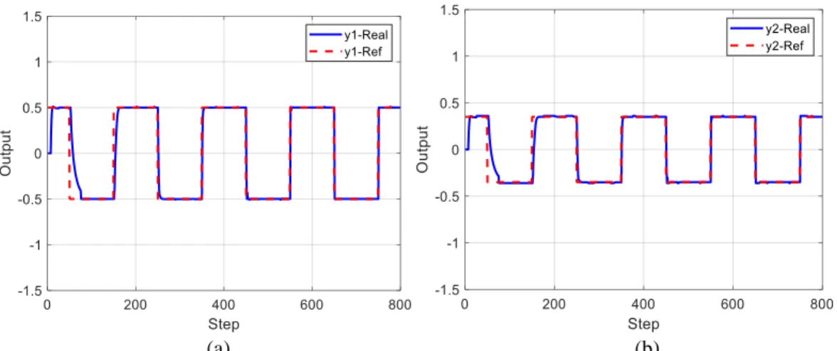
Figure 2.6. Simulation results in Example 2.4 using CFDL-based MFAC for a) system output y1, b) system output y2 . ... 71
Figure 2.7. Simulation results in Example 2.5 using PFDL-based MFAC for a) system output y1, b) system output y2 . ... 76
Figure 2.8. Simulation results in Example 2.6 using FFDL-based MFAC for a) system output y1, b) system output y2 . ... 79
Figure 3.1 Schematic of the WRSM chassis with the interlocked inverter. ... 85
Figure 3.2. The i-StARS machine without the inverter and the brush. ... 86
Figure 3.3. Diagram of the MOSFET’s connection in the FM600TU-07A module [4]. ... 87
Figure 3.4. Diagram of the electronic device assembled together. ... 87
Figure 3.5. The i-StARS machine and the coupled load machine. ... 88
Figure 3.6. Diagram of the Hall effect based position sensor. ... 88
Figure 3.7. Practical test bench prepared in the laboratory. ... 89
Figure 3.8. Electric diagram of the prepared powertrain. ... 89
Figure 3.9. Meshing of the full i-StARS machine with Gmsh-GetDP [1]. ... 90
Figure 3.10. Meshing of 1 pole of the i-StARS rotor and stator with Gmsh-GetDP [1]. ... 90
Figure 3.11. Comparison of the flux calculations in the complete meshed mashine and in the periodic meshed mashine. ... 91
Figure 3.12. Back-EMF in the i-StARS driven at 520 rpm as a function of the excitation current. ... 91
Figure 3.13. Simplified representation of the WRSM. ... 92
Figure 3.14. Representation of the WRSM in the dq fram. ... 93
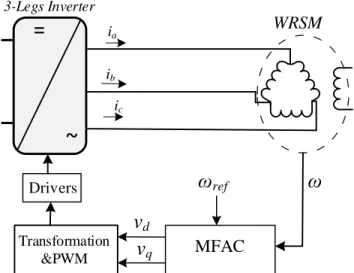
Figure 3.15. Control diagram of the studied WRSM drive system. ... 97
Figure 3.16. General control diagram of the studied system. ... 99
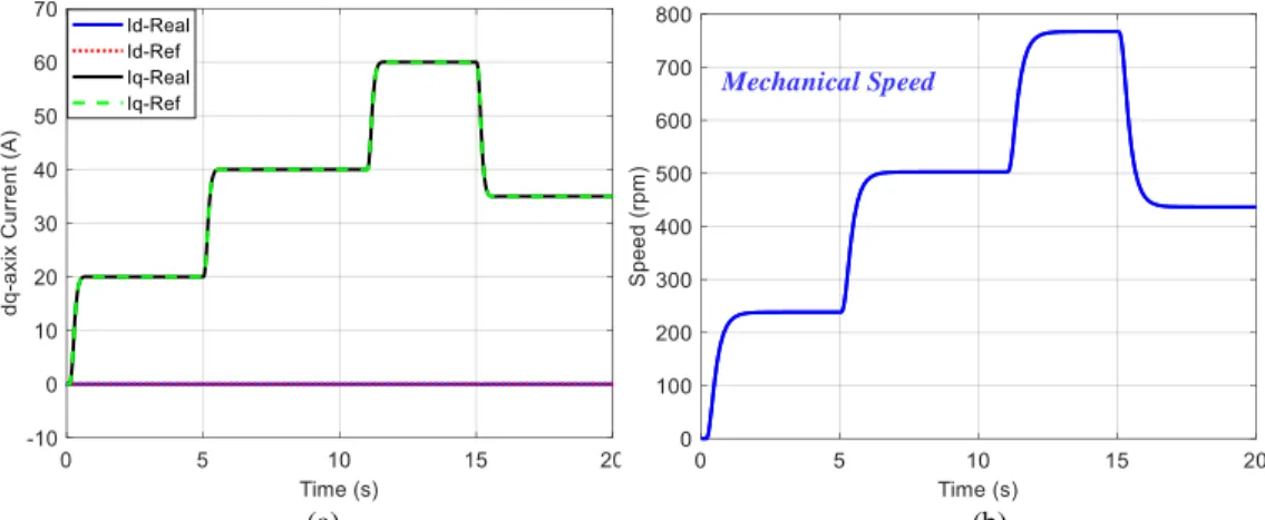
Figure 3.17. Simulation results of MFAC for, a) current, b) 𝑖𝑞 current, c) Mechanical speed of rotor, d) Control input signals, e) Phase currents 𝑖𝑎, 𝑖𝑏, 𝑖𝑐 in different operating points. ... 101
Figure 3.18. Simulation results of MFAC for, a) 𝑖𝑑 current, b) 𝑖𝑞 current, c) Mechanical speed of rotor, d) Control input signals, under +50% parameter variation and load torque disturbances. ... 102
Figure 3.19. Simulation results of PI controller for, a) 𝑖𝑑 and 𝑖𝑞 currents, b) Mechanical speed of rotor, in different operating points. ... 103
Figure 3.20. Simulation results of PI controller for, a) 𝑖𝑑 and 𝑖𝑞 currents, b) Mechanical speed of rotor, under +50% parameter variation and load torque disturbances. ... 103
Figure 3.21. Experimental results of MFAC for, a) 𝑑𝑞 frame phase currents, b) 𝑎𝑏𝑐 frame phase currents, c) Mechanical speed of rotor, d) Control input signals, during different operating points. ... 104
Figure 3.22. Experimental results of MFAC for, a) 𝑖𝑑 and 𝑖𝑞 currents, b) Mechanical speed of rotor, d) Control input signals, under load torque disturbance. ... 105
Figure 3.24. Experimental results of PI controller for, a) 𝑖𝑑 and 𝑖𝑞 currents, b) Mechanical speed of rotor, in
different operating poins. ... 106
Figure 3.25. Experimental results of PI controller for, a) 𝑖𝑑 and 𝑖𝑞 currents, b) Mechanical speed of rotor, under load torque disturbance. ... 107
Figure 3.26. Control diagram using Lyapunov based estimator [2]. ... 110
Figure 3.27. a) Current sensorless control diagram of the studied WRSM drive system, b) Structure of FFDL-based MFAC with 𝐿𝑢 = 𝐿𝑦 = 5. ... 112
Figure 3.28. Simulation results of MFAC for, a) 𝑖𝑑𝑞 current, b) Mechanical speed of rotor, in different operating points. ... 114
Figure 3.29. Simulation results of 𝑖𝑑𝑞 estimation compared to the actual current with a) nonlinear observer, b) EKF proposed in [2]. ... 114
Figure 3.30. Simulation results of MFAC for, a) 𝑖𝑑𝑞 current, b) Mechanical speed of rotor, under +50% parameter variation. ... 115
Figure 3.31. Simulation results of MFAC for, a) 𝑖𝑑𝑞 current, b) Mechanical rotor speed, under +50% parameter variation [2]. ... 115
Figure 3.32. Simulation results of MFAC for, a) 𝑖𝑑𝑞 current, b) Mechanical speed of rotor, by load variation from full-load to half-load. ... 116
Figure 3.33. a) MFAC tracking performance, b) online current estimation [28], at 𝜔 = 200 rpm. ... 117
Figure 3.34. a) MFAC tracking performance, b) online current estimation [28], at 𝜔 = 600 rpm. ... 117
Figure 3.35. a) MFAC tracking performance, b) online current estimation [2], at 𝜔 = 950 rpm. ... 117
Figure 3.36. Starting performance of MFAC for, a) 𝑖𝑑 and 𝑖𝑞 currents, and b) Mechanical speed of rotor at ω=600 rpm. ... 118
Figure 3.37. Online 𝑖𝑑𝑞 current estimation in starting condition [2]. ... 118
Figure 3.38. MFAC performance with a load step down at 600 rpm for, a) 𝑖𝑑 and 𝑖𝑞 currents, and b) Mechanical speed of rotor. ... 119
Figure 3.39. Online 𝑖𝑑𝑞 current estimation at 600 rpm with a load step down [2]. ... 119
Figure 3.40. MFAC performance with a load step up at 600 rpm for, a) 𝑖𝑑 and 𝑖𝑞 currents, and b) Mechanical speed of rotor. ... 120
Figure 4.1. Two-loop control for a boost converter [22]. ... 125
Figure 4.2. Studied boost converter. ... 127
Figure 4.3. Control block diagram of the studied boost converter. ... 127
Figure 4.4. General control block diagram of the studied boost converter. ... 129
Figure 4.5. Tracking responses of inductor current and output voltage with a) MFAC, and b) PI controller. ... 131
Figure 4.6. Startup and steady-state responses of inductor current and output voltage with a) MFAC, and b) PI controller. ... 131
Figure 4.8. Responses of inductor current and output voltage with a variation of input voltage using a) MFAC,
and b) PI controller. ... 132
Figure 4.9. Responses of inductor current and output voltage under parameter variation using a) MFAC, and b) PI controller. ... 133
Figure 4.10. Experimental setup... 133
Figure 4.11. Startup and steady-state responses of inductor current and output voltage while 𝑣𝑜𝑟𝑒𝑓 = 50𝑉 using a) MFAC, and b) PI controller. ... 134
Figure 4.12. Startup and steady-state responses of inductor current and output voltage while 𝑣𝑜𝑟𝑒𝑓 = 40𝑉 using a) MFAC, and b) PI controller. ... 134
Figure 4.13. Tracking responses of inductor current and output voltage using a) MFAC, and b) PI controller, while output voltage vary as 𝑣𝑜𝑟𝑒𝑓 = 40𝑉 → 50𝑉 → 40𝑉. ... 135
Figure 4.14. Tracking responses of inductor current and output voltage using a) MFAC, and b) PI controller, while output voltage vars as 𝑣𝑜𝑟𝑒𝑓 = 30𝑉 → 50𝑉 → 30𝑉. ... 135
Figure 4.15. Experimental results using MFAC with a) +10%, and b) -10%, changes of input voltage 𝑉𝑖𝑛. 136 Figure 4.16. Experimental results using PI controller with a) +10%, and b) -10%, changes of input voltage 𝑉𝑖. ... 136
Figure 4.17. Experimental results under -50% variation of resistance load 𝑅𝐿 using a) MFAC, and b) PI controller. ... 137
Figure 4.18. Topology of single-phase DAB converter. ... 139
Figure 4.19. Operation waveforms of single-phase DAB converter. ... 140
Figure 4.20. Topology of three-phase DAB converter. ... 141
Figure 4.21. Operation waveforms of three-phase DAB converter: a) 0 < 𝜑 ≤ 𝜋3, b) 𝜋3 < 𝜑 ≤ 2𝜋3. ... 141
Figure 4.22. Control diagram of the studied three-phase DAB converter.. ... 146
Figure 4.23. Startup and steady-state responses while converter is loaded by 𝑃 = 1500𝑊, a)output voltage, b)created phase shift, c)𝑑𝑞 frame primary side currents, d) primary and secondary side phase voltages, e) reactive power and f) active power.. ... 149
Figure 4.24. Startup and steady-state responses while converter is loaded by 𝑃 = 3000𝑊, a)output voltage, b)created phase shift, c)𝑑𝑞 frame primary side currents, d) primary and secondary side phase voltages, e) reactive power and f) active power.. ... 150
Figure 4.25. Obtained results by parameters and load variations for a) output voltage, b) created phase shift, c) 𝑑𝑞 frame primary side currents, d) primary and secondary side phase voltages, e) reactive power and f) active power. ... 151
Figure 4.26. Obtained results under output voltage variation for a) output voltage, b) created phase shift, c) 𝑑𝑞 frame primary side currents, d) primary and secondary side phase voltages, e) reactive power and f) active power. ... 152
L
IST OF
T
ABLES
Table 1.1 Characteristics of BEVs, HEVs, and FCVs [5] ... 7
TABLE 3.1:SYMBOLES USED IN (3.13) ... 95
TABLE 3.2: PARAMETERS USED IN MFAC ... 100
TABLE 3.3: PARAMETERS USED IN MFAC ... 113
TABLE 4.1:SYSTEM PARAMETERS ... 130
TABLE 4.2:CONTROL PARAMETERS FOR PI ... 130
TABLE 4.3:MFACPARAMETERS ... 131
TABLE 4.4:SWITCHING STATES OF THREE-PHASE DAB CONVERTER ... 144
TABLE 4.5:THREE-PHASE DABPARAMETERS ... 145
A
BBREVIATIONS
AC Alternating current BEV Battery electric vehicle BIBO Bounded-input bounded-output CFDL Compact form dynamic linearization
CO2 Carbon dioxide
DAB Dual active bridge
DC Direct current
DDC Data driven control DL Dynamic linearization
DPS Dual phase shift
DTC Direct torque control EKF Extended Kalman filter
EM Electric motor
ESS Energy storage system
EV Electric vehicle
FCV Fuel cell vehicle FEA Finite element analysis
FFDL Full form dynamic linearization
GA Genetic algorithm
GHG Green house gases
HEV Hybrid electric vehicle ICE Internal combustion engine IFT Iterative feedback tuning IPM Internal permanent magnet
i-StARS Integrated stator alternator revisable system
LV Low voltage
MBC Model based control MFAC Model free adaptive control MIMO Multi input multi output MISO Multi input single output
PFDL Partial form dynamic linearization
PG Pseudo gradient
PI Proportional integral
PID Proportional integral derivative PJM Pseudo jacobian matrix
PM Permanent magnet
PPD Pseudo partial derivative
PPJM Pseudo partitioned jacobian matrix PWM Pulse width modulation
RFOC Rotor field-oriented control SISO Single input single output SPS Single phase shift
UC Ultra capacitor
UDFVC Unified direct flux vector control UPS Uninterruptable Power Supplies VRFT Virtual reference feedback tuning WRSM Wired rotor synchronous machine ZVS Zero voltage switching
INTRODUDTION
The increasing amount of greenhouse gases (GHG) are considered as a major challenge for climate change and global warming. Transportation sector contributes to a 24% of global CO2 emissions which are considered
as the main composition of GHGs. The growing concerns about climate change and energy security have accelerated a global transition to a more sustainable transport system. Electric cars, representing an innovative technology with the potential to reduce greenhouse gas emissions and support the mitigation of climate change, have gained substantial interests in recent years.
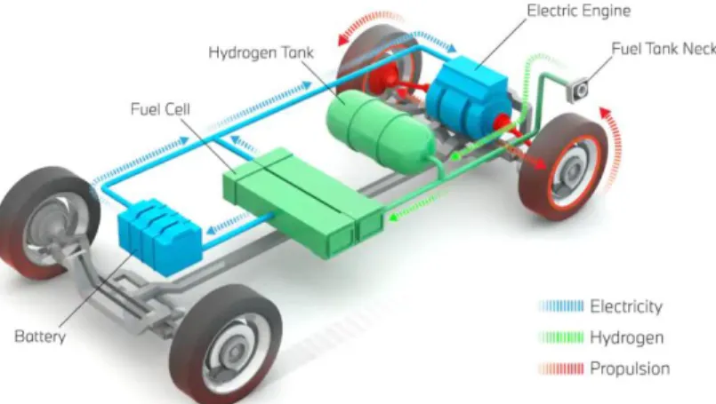
So far, different configurations and options of the EVs have been proposed in the industry. EVs can run solely on electric propulsion or they can have an internal combustion engine (ICE) working alongside it. Having only batteries as energy source constitutes the basic kind of EV, but there are kinds that can employ other energy source modes. These can be called hybrid EVs (HEVs). Vehicles using two or more types of energy source, storage or converters can be called as an HEV as long as at least one of those provide electrical energy. There is another kind of EVs that use chemical reactions to produce electricity. The hydrogen is the fuel that carries out this reaction, so they are called fuel cell vehicles (FCV).
At the dawn of the second automotive century it is apparent that the nature of the automotive industry has become very competitive. In this situation, the automotive companies need to stay competitive by proposing new strategies to reach to a good performance with minimum cost. To do so, developing mild hybrid solutions have been Valeo’s first choice. The mild hybrid solution has some advantages compared to the Start-Stop solution which is the most frequently used hybridization type on vehicles. In Start-Stop type, the electric actuator activates only for the restarting of the fuel engine, while in mild-hybrid solution the electric actuator can be activated each time the vehicle needs a power boost. Finally, the technical solution proposed by firm Valeo has been resulted in developing the “i-StARS” (integrated Starter Alternator Reversible System). The topology used for i-StARS machine is a doubly-fed claw pole wired rotor synchronous machine (WRSM). In order to optimize this kind of machine for mild hybrid application, a first study has been realized in the GREEN laboratory to enhance the finite elements modeling of a claw pole WRSM within Dr. Devornique’s thesis work.
The second solution for Valeo, to stay competitive in automotive industry, was the cost optimization on the electronic part of the powertrain. To do so, Valeo proposed a study to remove the phase current sensors for the control of the i-StARS machine. Indeed, on a doubly-fed machine, at least 4 current sensors are required to control the electric powertrain. As it will be detailed in chapter three, the system operates under low voltage (12 V) and the currents in the stator are high (up to 150 A) and the current sensors capable of measuring such large currents are rather expensive. Thus, the benefits of removing those sensors on the manufacturing costs are clear. The proposed study was in collaboration with GREEN laboratory which resulted in PhD thesis study of Dr. Adrien CORNE. According to Dr. Corne’s thesis work, a state observer is used to estimate the stator currents using the available measures, then the estimated currents are injected in a closed-loop controller. According to this configuration, a reliable current sensorless control method was achieved for mentioned WRSM system.
Despite all the advantages of the observation-based current sensorless control method, it has also some critical limitations. Since this method uses a state model of the system to estimate the unmeasured variables its effectiveness is highly dependent on the correctness of this model. However, reaching a very precise model is usually impossible or at least time-consuming. In addition, the performance of this control method is very sensitive to the parameters. The transient response is another challenge related to this method that contains a considerable amount of error.
According to the abovementioned statements, the aim of this thesis work is to continue the development of new actuator control laws that will improve the reliability of the AC drive train used in automotive area. In this context, the control of the AC machine and the power electronic interface will be considered. The objective is to design a controller to guarantee the stability of the system in both transient and steady-state condition. The designed controller is subjected to work with minimum number of sensors and fix the limitations related to the already developed sensorless controllers. To do so, the data-driven control (DDC) theory, as a good alternative for existing methods, is considered to be used in control of AC drive systems thanks to its intrinsic features. In this regard, the model-free adaptive control (MFAC), as a candidate of the data-driven control (DDC), is considered to be used in thesis work to overcome the previously mentioned limitations.
This thesis work consists of four chapters. In chapter 1, a brief background of the EVs is presented. This mainly includes a brief overview of the battery EVs, HEVs and FCVs. In this chapter, the control approaches and fundamentals of a standard electric drive system are also reviewed. The last section of this chapter is allocated to present the context and contribution of this study.
In chapter 2, the basic fundamentals, different categories and applications of data-driven control (DDC) methods are presented. The main focus of this chapter will be on presentation of the model-free adaptive control (MFAC). In this regard, the theory, application, stability analysis and controller design approach of MFAC are provided for any nonlinear system with single-input single-output (SISO), multi-input single-output (MISO) and multi-input multi-output (MIMO) structure. Some examples are also provided to simplify the understanding the application of the MFAC. The main purpose of this chapter is to provide the basic knowledge about the DDC theories that is used in this thesis work.
The third chapter is divided into three main sections. The first section of this chapter is dedicated to the modeling of the studied i-StARS system, including a claw-pole WRSM, an inverter, an input filter and a 12V battery. The modeling presented in this section includes a modeling based on finite elements analysis (FEA) and a modeling based on the electric approach for the studied WRSM. In second section of this chapter, the MFAC is developed for current control of the studied WRSM system. In this configuration the stator phase currents are measured and controlled directly. The aim behind this work is to show that the MFAC is totally independent from system model and parameter variations. In third section of this chapter, the MFAC is used for current sensorless control of the studied WRSM system. In this case, neither any measurements nor any observations are considered for stator phase currents and all the control tasks are considered to be done with only measuring the mechanical rotor speed. The effectiveness of the MFAC in control of the WRSM system, with and without using current sensors, is tested in simulation and experimental works and compared with
another existing current controller, such as PI, and current sensorless control algorithm, such as observation-based controller.
In chapter 4, control of the power converters, used in electric drive systems, are provided. Since the electric drive systems include several power converters, the control of two different converters (a DC/DC boost converter and a three-phase dual-active bridge (DAB) converter) are studied in this chapter, respectively. Similar to the chapter 3, the goal is to design a robust and reliable controller with minimum number of sensors for mentioned converters. In this case, the output voltage of the converters is considered as the only measured variable to design a robust controller using MFAC. The effectiveness of the MFAC in control of the power converters is tested in simulation and experimental works and compared with another existing control algorithm.
Chapter-1 BACKGROUND
OF
HYBRID
ELECTRIC
VEHICLES
Contents
CHAPTER-1 BACKGROUND OF HYBRID ELECTRIC VEHICLES ... 5 INTRODUCTION ... 6 1.1. ELECTRIC,HYBRID AND FUEL CELL VEHICLES ... 7 Electric Vehicles ... 8
1.1.1.1. Advantages of EVs over traditional vehicles ... 10 1.1.1.2. Challenges for EVs... 11
Hybrid electric vehicles ... 13 Fuel cell vehicles ... 16 1.2. FUNDAMENTALS OF ELECTRIC DRIVES ... 17 The Electric drive structure ... 17 Vector control for Electric drive system ... 19
1.2.2.1. Rotor field oriented control ... 21 1.2.2.2. Direct torque control ... 22 1.2.2.3. Unified direct flux vector control ... 23
Measured variables in a standard drive ... 24 1.3. CONTEXT OF THE STUDY ... 25 Existing observation-based current sensorless control for WRSM ... 26 Contribution ... 28 CONCLUSION ... 29
Introduction
The automotive industry has been growing over the years and continues to grow today. Influenced by both government regulations and consumer demand, auto manufacturers have continued to pursue technologies to improve efficiency and fuel economy [1]. However, the highly developed automotive industry and the large number of automobiles in use around the world have caused and are still causing serious problems for society and human life. Deterioration in air quality, global warming, and a decrease in petroleum resources are becoming the major threats to human beings [2]. By increasing the global environmental concern, the importance of reducing green house gases (GHG) emissions became more apparent. In this regard, the European Union have made an agreement to increase the taxes of the emissions of GHG for the industries inside european countries. Approval of this agreement have widely influenced the automotive industries. Since most of the vehicles running today are still powered by internal combustion engines (ICE), the transportation industry is responsible for an estimated 25% to 30% of the global greenhouse effect gas emission according to the International Energy Agency in its Global EV Outlook [3], [4]. Consequently, the new European standards impose increasingly restrictive limits on CO2 emissions per km. This is an important industrial issue for
automakers.
More and more stringent emissions and fuel consumption regulations are stimulating an interest in the development of safe, clean, and high-efficiency transportation. In this regard, electrification of transport is considered as one of the relevant solutions to reduce emissions of greenhouse gases. It has been well recognized that electric, hybrid electric, and fuel cell-powered drive train technologies are the most promising solutions to the problem of land transportation in the future [2]. Indeed, the automotive industry is moving towards hybrid and electric vehicles in which an electric traction chain is present. This consists of an electric machine, powered by a static converter of power electronics connected to a source of electrical energy and storage elements. For more than two decades, different topologies have been studied for electric traction and several solutions have been marketed. These products are increasingly light, reliable and efficient while respecting the constraints of the automakers on the costs.
According to the abovementioned statements, this thesis study is founded based on the latest trend in the automotive industry which is the electrification of the vehicles. The aim of this thesis work is to continue the development of new actuator control laws that will improve the reliability of the AC drive train used in automotive area. In this context, the control of the AC machine and the power electronic interface will be considered. The objective is to design a controller to guarantee the stability of the system in both transient and steady-state condition. The goal is to develop a controller to work with minimum number of sensors. Indeed, there are already several sensors in a standard traction chain. However, these generate significant additional costs because of their frequent failures and the need for a very expensive replacement of manpower.
This chapter will first discuss the importance and advantages of the electric, hybrid and fuel cell vehicles. Classification of the existing hybrid electric vehicles will also be reviewed briefly. Fundamentals of a standard electric drive system will be given in second part. The details about the context and goal of this study will be
1.1. Electric, Hybrid and Fuel Cell Vehicles
Vehicles equipped with conventional internal combustion engines (ICE) have been in existence for over 100 years. With the increase of the world population, the demand for vehicles for personal transportation has increased dramatically in the past decade. This trend of increase will only intensify with the catching up of developing countries, such as China, India, and Mexico. The demand for oil has increased significantly [5].
Another problem associated with the ever-increasing use of personal vehicles is the emissions. The greenhouse effect, also known as global warming, is a serious issue that we have to face. There have been increased tensions in part of the world due to the energy crisis. Government agencies and organizations have developed more stringent standards for the fuel consumption and emissions. Nevertheless, with the ICE technology being matured over the past 100 years, although it will continue to improve with the aid of automotive electronic technology, it will mainly rely on alternative evolution approaches to significantly improve the fuel economy and reduce emissions[1], [2], [5], [6].
In recent decades, the research and development activities related to transportation have emphasized the development of high efficiency, clean, and safe transportation. Electric vehicles (EVs), hybrid electric vehicles (HEVs), and fuel cell vehicles (FCVs) have been typically proposed to replace conventional vehicles in the near future [1], [2], [5]. In this category, the electric vehicles (full electric vehicles) uses only electric energy for propulsion, hybrid electric vehicles (HEV) uses both fossil fuel and electric energy for propulsion and fuel cell electric vehicles (FCV) use hydrogen fuel cells to generate energy for propulsion. Table 1.1 shows a comparison of the major characteristics of EVs, HEVs and FCVs.
This section reviews the different aspects of EVs, HEVs, and FCVs. It also gives a brief review of the development of electric vehicles, hybrid electric vehicles, and fuel cell technology.
Table 1.1 Characteristics of BEVs, HEVs, and FCVs [5]
Types of EVs Battery EVs Hybrid EVs Fuell cell EVs
Propulsion • Electric motor drives • Electric motor drives
• Internal combustion engines • Electric motor drives
Energy system • Battery
• Ultracapacitor • Battery• Ultracapacitor • ICE generating unit
• Fuel cells
• Need battery/ultracapacitor to enhance power density for starting
Energy source & infrastructure
• Electric grid charging facilities
• Gasoline stations • Electric grid charging
facilities (for Plug In Hybrid)
• Hydrogen
• Hydrogen production and transportation infrastructure
Characteristics • Zero emission• High energy efficiency • Independent on crude oils • Relatively short range • High initial cost • Commercially available
• Very low emission • Higher fuel economy as
compared with ICE vehicles • Long driving range • Dependence on crude oil (for
non Plug In Hybrid) • Higher cost as compared
with ICE vehicles • The increase in fuel
economy and reduce in emission depending on the power level of motor and battery as well as driving cycle
• Commercially available
• Zero emission or ultra low emission
• High energy efficiency • Independent on crude oil (if
not using gasoline to produce hydrogen • Satisfied driving range • High cost
Major issues • Battery and battery management • Charging facilities • Cost
• Multiple energy sources control, optimization and management
• Battery sizing and management
• Fuel cell cost, cycle life and reliability
1.1.1. Electric Vehicles
An electric vehicle (EV), uses one or more electric motors or traction motors for propulsion. Three main types of electric vehicles exist, those that are directly powered from an external power station, those that are powered by stored electricity originally from an external power source, and those that are powered by an on-board electrical generator, such as an engine (a hybrid electric vehicle), or a hydrogen fuel cell. Electric vehicles include electric cars, electric trains, electric lorries, electric airplanes, electric boats, electric motorcycles and scooters and electric spacecraft [7].
Battery-powered electric vehicles were one of the solutions proposed to tackle the energy crisis and global warming. However, the high initial cost, short driving range, long charging (refueling) time, and reduced passenger and cargo space have proved the limitation of battery-powered EVs.
Previously, the EV was mainly converted from the existing ICEV by replacing the internal combustion engine and fuel tank with an electric motor drive and battery pack while retaining all the other components, as shown in Figure 1.1. Drawbacks such as its heavy weight, lower flexibility, and performance degradation have caused the use of this type of EV to fade out. In its place, the modern EV is built based on original body and frame designs. This satisfies the structure requirements unique to EVs and makes use of the greater flexibility of electric propulsion.
A modern electric drive train is conceptually illustrated in Figure 1.2. The drive train consists of three major subsystems: electric motor propulsion, energy source, and auxiliary. The electric propulsion subsystem is comprised of a vehicle controller, power electronic converter, electric motor, mechanical transmission, and driving wheels. The energy source subsystem involves the energy source, the energy management unit, and the energy refueling unit. The auxiliary subsystem consists of the power steering unit, the hotel climate control unit, and the auxiliary supply unit. Based on the control inputs from the accelerator and brake pedals, the vehicle controller provides proper control signals to the electronic power converter, which functions to regulate the power flow between the electric motor and energy source. The backward power flow is due to the
Electric energy source Electric motor drive Mechanical transmission Wheel Wheel
9
regenerative braking of the EV and this regenerated energy can be restored to the energy source, provided the energy source is receptive. Most EV batteries as well as ultracapacitors and flywheels readily possess the ability to accept regenerated energy. The energy management unit cooperates with the vehicle controller to control the regenerative braking and its energy recovery. It also works with the energy refueling unit to control the refueling unit, and to monitor the usability of the energy source. The auxiliary power supply provides the
Vehicle controller Electronic power converter Electric motor Mechanical transmission Wheel Wheel Energy management unit Energy source Energy refueling unit Auxiliary power supply Power steering unit Hotel climate control unit
Electric propulsion subsystem
Energy source
subsystem Auxiliary subsystem
Steering wheel Mechanical link Electric link Control link Brake Accelerator
Figure 1.2 Conceptual illustration of general EV configuration [2].
Figure 1.3 Conceptual illustration of general EV configuration [2].
M GB D M GB D D FG M FG M FGM M M M M C: Clutch D: Differential FG: Fixed gearing GB: Gearbox M: Electric motor (a) (b) (c) (d) (e) (f)
necessary power at different voltage levels for all the EV auxiliaries, especially the hotel climate control and power steering units.
There are a variety of possible EV configurations due to the variations in electric propulsion characteristics and energy sources, as shown in Figure 1.3.
a) Figure 1.3 (a) shows the configuration of the first alternative, in which an electric propulsion replaces the IC engine of a conventional vehicle drive train. It consists of an electric motor, a clutch, a gearbox, and a differential. The clutch and gearbox may be replaced by automatic transmission. The clutch is used to connect or disconnect the power of the electric motor from the driven wheels. The gearbox provides a set of gear ratios to modify the speed-power (torque) profile to match the load requirement. The differential is a mechanical device (usually a set of planetary gears), which enables the wheels of both sides to be driven at different speeds when the vehicle runs along a curved path.
b) With an electric motor that has constant power in a long speed range, a fixed gearing can replace the multispeed gearbox and reduce the need for a clutch. This configuration not only reduces the size and weight of the mechanical transmission, but also simplifies the drive train control because gear shifting is not needed.
c) Similar to the drive train in (b), the electric motor, the fixed gearing, and the differential can be further integrated into a single assembly while both axles point at both driving wheels. The whole drive train is further simplified and compacted.
d) In Figure 1.3 (d), the mechanical differential is replaced by using two traction motors. Each of them drives one side wheel and operates at a different speed when the vehicle is running along a curved path.
e) In order to further simplify the drive train, the traction motor can be placed inside a wheel. This arrangement is the so-called in wheel drive. A thin planetary gear set may be used to reduce the motor speed and enhance the motor torque. The thin planetary gear set offers the advantage of a high-speed reduction ratio as well as an inline arrangement of the input and output shaft. f) By fully abandoning any mechanical gearing between the electric motor and the driving wheel,
the out-rotor of a low-speed electric motor in the in-wheel drive can be directly connected to the driving wheel. The speed control of the electric motor is equivalent to the control of the wheel speed and hence the vehicle speed. However, this arrangement requires the electric motor to have a higher torque to start and accelerate the vehicle.
1.1.1.1. Advantages of EVs over traditional vehicles
The most obvious advantage of any electric car over combustion engine car is its zero tail pipe emissions, which is an unquestionable fact. However, the electric energy used for the propelling of the engine still needs to be produced somewhere to supply its consumption. Thus, the EVs only shift the air pollution up on its production stream towards the electricity plants, which in most of the cases still use fossil fuels for their
the nonurban areas and the agglomerations profit from locally lower emissions and the and pollutants harmful to the health, which go hand in hand (i.e. CO, NOx, THC, NMHC) [8]. The emissions produced by the power plants are far easier to manage in a unified form at the plants, producing the energy with much higher carbon dioxide efficiency, than in the case of huge amounts of single cars in the daily traffic. Another fact is the reduction of noise caused by the traffic, since the EV’s motor running is significantly quieter, thanks to the missing exhaust [8].
Another major advantage of any type of fully electrically powered vehicle is a significantly lower consumption cost. Moreover, the price and consumption of kWh of EVs represent a significant difference of the consumption of any gasoline or diesel car.
Moving on, the electric engine entirely misses the transmission with the clutch and consists of just very few moving particles, unlike the combustion engine. Therefore, there is no need for change of any type of oil, coolant, water or start sparks of the engine. This fact has a consumer-friendly aspect of less wear out of the engine components, going hand in hand with lower maintenance costs, dedicated to the service of the vehicle [9]. The electric cars are usually enhanced with the system of regenerative engine braking, when the foot is removed from the gas pedal. This process eventually prolongs the lifetime of the braking pads and simultaneously recharges the batteries while braking.
The average efficiency of today’s combustion engines, namely the way how effectively it operates with the consumed fuels, is between 25% and 35%. The electric engines, on the other hand, have more than triple the amount of efficiency, at least 90% [10].
The next positive impact of the missing transmission and the overall nature of the electric unit is its instant torque, offering maximum power from the standstill, whereas a combustion engine can only achieve this at high speed [10]. The power delivery is extremely smooth and achievable at any moment of the drive, making it a security element in case of possible fast response needed in traffic situations, such as overtaking.
Finally yet importantly, the buy of any new EV is in many countries subsidized by the government, stimulating the public interest to purchase the EVs over the conventional automobiles in order to reduce the country’s dependency on foreign oil. This is usually the case for the fully electric BEVs, but subsidizing hybrid cars might be considered as well in many destinations.
1.1.1.2. Challenges for EVs
A. Range and batteries
The major barrier for buying any EV is the range of a single charge of the car, which is much lower than for any fully tanked conventional automobile. The vast majority of the EV market nowadays, are only able to travel from 80 to 160 km on a single charge (with the Tesla, however, up to 500km, but becoming very pricy) [10][11]. This could be considered sufficient as a daily range for most of the population, however, it is still incomparable with the range of any combustion engine vehicle. Those normally achieve 500km on a single tank, without being limited by the charging station network and being able to refill their tank at any gas station. For any regularly long-distance travelling driver, the limited range might present a problem.
Continuing the talk about the range of EVs, it markedly decreases while driving on the highway at speeds higher than 130km/h, at which the car needs more power. However, cruising up to the speed of 110km/h, the EVs usually still manage well without any significant range drops [10][11].
B. Charging
When somebody owns an electric car, his/her basic need is to have the possibility to charge it conveniently, in order to calm down his/her worries. In case of shorter distances around the town, for journeys to the work place, grocery stores or schools, the usual car range is most of the time sufficient for one day.
A majority of the EV owners (95%) usually charge their cars’ batteries during the night, when they are not using the car [10][11]. Anyway, not all the members of the population have the luxury of parking in a garage, where they can simply plug in their vehicle. Many people park their cars in the street and they would have to be lucky to have any public charging point in their living area [12].
The next problem occurs for trips that are longer than the one charge range of the vehicle. In this case, the customers are forced to rely on the charging points’ network. Although the number of charging stations is increasing, it is still incomparable with the convenience of the gas stations and their geographical density. The charging time is another issue, which might be solved with the so-called rapid chargers, adding to the vehicle’s range within less than an hour. However, their occurrence is rather rare today [12].
C. Purchase price
Finally, there is the question of the purchase price of any electric car, which is generally speaking much higher than any other conventional market product from given class and quality segment. The main reason for electric cars being so expensive is mainly their battery price, where we face nowadays the price of 350 USD per 1 kWh of its capacity [13]. Speaking of the purchase price of any EV, let us observe it through the example of fully battery electric Chevrolet Bolt, where the battery capacity is 60 kWh and its selling price is around
Fuel tank IC engine Generator Battery Power converter Electric motor Tr an sm iss io n Fuel tank IC engine Generator
Battery converterPower Electricmotor
Tr an sm iss io n Mech. coupler Fuel tank IC engine Battery Power converter Electric motor Tr an sm iss io n M ec h . co u p le r Fuel tank IC engine Generator/ motor
Battery converterPower Electricmotor
Tr an sm is si o n Mech. coupler Power converter
(a) Series hybrid (b) Parallel hybrid
(c) Series-parallel hybrid (d) Complex hybrid
37.495 USD in the US. Given the above-mentioned price of 1 kWh, we face a battery price of 21.000 USD, which is more than half of the final selling price [14]. This fact makes it difficult for the automakers to satisfy their profit margin, while trying to offer an affordable car and that is why the electric cars are more expensive than competing conventional vehicles.
1.1.2. Hybrid electric vehicles
The HEV was developed to overcome the disadvantages of both internal combustion engine (ICE) vehicles and the pure battery-powered electric vehicle. The HEV uses the onboard ICE to convert energy from the onboard gasoline or diesel to mechanical energy, which is used to drive the onboard electric motor, in the case of a series HEV, or to drive the wheels together with an electric motor, in the case of parallel or complex HEV. The purpose of hybrid electric vehicles is to achieve a better fuel economy and better car efficiency. The electric motor minimizes idling and improves the vehicle’s ability to stop and go, which is particularly useful in the city traffic. Moreover, the electric motor assists or fully donates the vehicle’s acceleration and the low- speed driving [10]. Another major advantage of the HEVs over the BEVs is, due to the addition of the combustion engine, the much higher range of the vehicle, when the batteries of the electric engine run out of power.
In hybrid vehicles, two or more sources of power/energy are combined to obtain the required power to propel the vehicle. HEVs combine the advantages of the electric motor drive and an internal combustion engine to propel the vehicle [15]. The architecture of a hybrid vehicle is loosely defined as the connection between the components that define the energy flow routes and control ports. Traditionally, HEVs were classified into two basic types: series and parallel. Recently, series– parallel and complex HEVs have been developed to improve the power performance and fuel economy [2][15]. All different topologies of the HEVs are shown in Figure 1.4 . The next few sections will review the topologies related to series hybrid vehicle, parallel hybrid vehicle, series-parallel hybrid vehicles, and complex hybrid vehicles. Thus, the various strategies to combine the ICE and traction motor in a hybrid arrangement will be highlighted.
A. Series HEV
In case of series hybrid system (Figure 1.4.a) the mechanical output is first converted into electricity using a generator. The converted electricity either charges the battery or can bypass the battery to propel the wheels via the motor and mechanical transmission. Conceptually, it is an ICE assisted Electric Vehicle (EV). There are six possible different operation modes in a series HEV [2][5]:
1) battery alone mode: engine is off, vehicle is powered by the battery only; 2) engine alone mode: power from ICE/G;
3) combined mode: both ICE/G set and battery provides power to the traction motor; 4) power split mode: ICE/G power split to drive the vehicle and charge the battery; 5) stationary charging mode;
6) regenerative braking mode.
• mechanical decoupling between the ICE and driven wheels allows the IC engine operating at its very narrow optimal region.
• nearly ideal torque-speed characteristics of electric motor make multi gear transmission unnecessary.
However, a series hybrid drivetrain has the following disadvantages:
• the energy is converted twice (mechanical to electrical and then to mechanical) and this reduces the overall efficiency.
• Two electric machines are needed and a big traction motor is required because it is the only torque source of the driven wheels.
The series hybrid drivetrain is used in heavy commercial vehicles, military vehicles and buses. The reason is that large vehicles have enough space for the bulky engine/generator system.
B. Parallel HEV
The parallel HEV (Figure 1.4.b) allows both ICE and electric motor (EM) to deliver power to drive the wheels. Since both the ICE and EM are coupled to the drive shaft of the wheels via two clutches, the propulsion power may be supplied by ICE alone, by EM only or by both ICE and EM. The EM can be used as a generator to charge the battery by regenerative braking or absorbing power from the ICE when its output is greater than that required to drive the wheels. The following are the possible different operation modes of parallel hybrid [5][2][15]:
1) motor alone mode: engine is off, vehicle is powered by the motor only; 2) engine alone mode: vehicle is propelled by the engine only;
3) combined mode: both ICE and motor provides power to the drive the vehicle;
4) power split mode: ICE power is split to drive the vehicle and charge the battery (motor becomes generator);
5) stationary charging mode;
6) regenerative braking mode (include hybrid braking mode). The advantages of the parallel hybrid drivetrain are:
• both engine and electric motor directly supply torques to the driven wheels and no energy form conversion occurs, hence energy loss is less.
• compactness due to no need of the generator and smaller traction motor. The drawbacks of parallel hybrid drivetrains are:
• mechanical coupling between the engines and the driven wheels, thus the engine operating points cannot be fixed in a narrow speed region.
• The mechanical configuration and the control strategy are complex compared to series hybrid drivetrain.
C. Series-Parallel HEV
The series-parallel HEV is a combination of the series and parallel hybrids. There is an additional mechanical link between the generator and the electric motor, compared to the series con- figuration, and an additional generator compared to the parallel hybrid, as shown in Figure 1.4.c With this design, it is possible to combine the advantages of both the series and parallel HEV configurations. It must be highlighted here that the series-parallel HEV is also relatively more complicated and expensive. There are many possible combinations of the ICE and traction motor. Two major classifications can be identified as electric-in- tensive and engine-intensive. The electric-intensive series-parallel HEV configuration indicates that the electric motor is more active than the ICE for propulsion, whereas, in the engine-in- tensive case, the ICE is more active. A common operative characteristic for both types of series-parallel HEV systems is that the electric motor is used alone at start with ICE turned off [2][5][16].
D. Complex HEV
The complex hybrid system (Figure 1.4.d) involves a complex configuration which cannot be classified into the above three kinds. The complex hybrid is similar to the series-parallel hybrid since the generator and electric motor is both electric machines. However, the key difference is due to the bidirectional power flow of the electric motor in complex hybrid and the unidirectional power flow of the generator in the series-parallel hybrid. The major disadvantage of complex hybrid is higher complexity.
In addition to the classification above, HEVs can be also classified into the following categories according to the level of hybridization and electric power [5].
a. Micro hybrid
The typical electric motor power for a sedan micro hybrid is about 2.5 kW at 12 V. It is essentially the integration of starter and alternator in the conventional ICE vehicle. The main function of the electric motor is for start and stop, hence the energy saving gained mainly is due to using the motor for start and stop. In city driving where there are frequent starts and stops, the energy saving may reach about 5% to 10%. The cost of a micro hybrid is only few percent higher than that of conventional vehicle, since the motor is small and the structure is simple. In the market, there is the C3 Citroen micro hybrid using the Valeo motor system.
b. Mild hybrid
The typical electric motor power for a sedan mild hybrid is about 10–20 kW at 100– 200 V. In this case, the motor is designed in a flat shape and is directly coupled with the engine. The high ratio of diameter to length of the motor enables the motor to have high inertia such that the original flywheel of the engine can be removed. The motor can join the propulsion as in parallel hybrid architecture. In city driving, typically it can save energy 20%–30%, but the cost will also increase 20%–30%. Available models are the Honda Civic and Honda Insight that belong to the mild hybrid category.
The typical electric motor power for a full sedan hybrid is about 50 kW at 200–300 V. Normally, there is a motor, generator, and engine, adopting series–parallel or a complex hybrid architecture. With the aid of power split devices such as a planetary gear, the power flow among engine, motor, generator, and battery is flexible in order to achieve optimum drive performance at maximum energy efficiency and minimum emission. The propulsion can be executed by motor only (for start and stop), engine only (for cruising whenever the engine at optimum operation region), or a combination of motor and engine (for sudden acceleration or normal driving when the required propulsion power is less than the engine optimum power range, thus the engine will drive the generator to charge the battery, and hence the engine will deliver more power than the required propulsion power such as that to reach optimum operation region). Typically, a full hybrid in city driving can save energy about 30%– 50%, while the cost increases about 30%–40%. The full hybrid vehicles can be further subdivided into Synergy Hybrid and Power Hybrid. Synergy Hybrid compromises the drive performance, energy efficiency, and emission reduction. In this subcategory, the engine is downsized as compared with conventional vehicle, such as in the Toyota Prius. Power Hybrid is aiming to have better driving performance, thus the engine is not downsized, and with the conjunction of the motor, the vehicle will have better drive performance as compared with a conventional vehicle, such as in the Toyota Highlander.
1.1.3. Fuel cell vehicles
A typical fuel cell-based propulsion system is shown in Figure 1.5 Fuel cell electric vehicles (FCVs) are powered by hydrogen. FCVs use a propulsion system similar to that of electric vehicles, where energy stored as hydrogen is converted to electricity by the fuel cell. Unlike conventional internal combustion engine vehicles, they produce no harmful tailpipe emissions. FCVs are fueled with pure hydrogen gas stored in a tank on the vehicle. Similar to conventional internal combustion engine vehicles, they can fuel in less than 5 minutes and have a driving range over 300 miles. FCVs are equipped with other advanced technologies to increase efficiency, such as regenerative braking systems, which capture the energy lost during braking and store it in a battery. Major automobile manufacturers are offering a limited but growing number of production
Figure 1.8 Propulsion system for a fuel-cell vehicle.
![Figure 1.2 Conceptual illustration of general EV configuration [2].](https://thumb-eu.123doks.com/thumbv2/123doknet/14718166.750615/27.918.202.701.112.411/figure-conceptual-illustration-general-ev-configuration.webp)
![Figure 1.14 Analogy between (separately excited) dc machine and vector controlled ac machine [192] .](https://thumb-eu.123doks.com/thumbv2/123doknet/14718166.750615/38.918.228.764.107.426/figure-analogy-separately-excited-machine-vector-controlled-machine.webp)
![Figure 1.26 Block diagram of the vector control of an AC WRSM [32].](https://thumb-eu.123doks.com/thumbv2/123doknet/14718166.750615/43.918.210.743.803.1046/figure-block-diagram-vector-control-ac-wrsm.webp)
![Figure 1.28 Block diagram of the observation-based current sensorless control of an AC WRSM [32]](https://thumb-eu.123doks.com/thumbv2/123doknet/14718166.750615/44.918.208.737.767.1044/figure-block-diagram-observation-based-current-sensorless-control.webp)