HAL Id: hal-02072140
https://hal.archives-ouvertes.fr/hal-02072140
Submitted on 18 Mar 2019
HAL is a multi-disciplinary open access archive for the deposit and dissemination of sci-entific research documents, whether they are pub-lished or not. The documents may come from teaching and research institutions in France or abroad, or from public or private research centers.
L’archive ouverte pluridisciplinaire HAL, est destinée au dépôt et à la diffusion de documents scientifiques de niveau recherche, publiés ou non, émanant des établissements d’enseignement et de recherche français ou étrangers, des laboratoires publics ou privés.
Modeling of the Powered Two-Wheeler dynamic
behavior for emergency situations analysis
Laura Costa, Christophe Perrin, Maxime Dubois-Lounis, Thierry Serre, Nacer
K M’Sirdi
To cite this version:
Laura Costa, Christophe Perrin, Maxime Dubois-Lounis, Thierry Serre, Nacer K M’Sirdi. Modeling of the Powered Two-Wheeler dynamic behavior for emergency situations analysis. 16th International Con¬ference Vehicle System Dynamics, Identification and Anomalies ; VSDIA 2018, November 5 - 7, 2018, Nov 2018, Budapest„ Hungary. �hal-02072140�
Modeling of the Powered Two-Wheeler dynamic behavior for
emergency situations analysis
Laura COSTAa&b, Christophe PERRINa, Maxime DUBOIS-LOUNISa,
Thierry SERREa, Nacer K. M’SIRDIb
a IFSTTAR LMA
304, chemin de la Croix Blanche 13300 Salon de Provence, France
b Aix-Marseille University LSIS UMR CNRS 7296
Avenue Escadrille Normandie Niemen 13000 Marseille,France Received: November 5, 2018
ABSTRACT
This paper deals with a numerical modelling of the Powered Two-Wheelers (PTW) dynamic in order to simulate its behaviour during emergency situations. Firstly, a multibody model of a Honda VFR has been developed. It consists of six bodies and eleven degrees of freedom and takes into account the specificities to simulate hard braking, avoidance and slalom manoeuvres. In parallel, a motorcycle was instrumented to conduct a series of emergency manoeuvres in order to validate the model. The experimental tests have been compared to the simulated model and results give good correlations showing that the model is well adapted to simulate emergency situations.
Keywords: Power Two Wheeler, motorcycle dynamics, experimental tests, numerical modelling, multibody simulation
1. INTRODUCTION
In France, users of PTW are less than 2% of traffic but, in the accidents, represent 43% of serious injuries and 23% of killed [1]. One of the different issues can be explained by a problem of the manoeuvrability dynamic capacity of this kind of vehicle for emergency situation. In the field of kinematic accident reconstruction, more or less complex PTW dynamic behaviour models are used to define levels of speed or acceleration achieved by these vehicles. They allow in particular to reconstruct the accident in its different phases of approach, emergency, impact and post-collision. Understanding the dynamic behaviour of these vehicles is difficult during the pre-crash phase because the dynamics of PTW is more complicated than cars and less studied so far [2].
Several PTW dynamic behaviour models have been developed. In 2001 Sharp and Limebeer [3] developed a model with 8 bodies and 13 degrees of freedom dedicated to study the stability and control analysis. The automated model building platform used is AutoSim. This code was used to generate a variety of linear and nonlinear models in symbolic form. In 2004 Sharp, Evangelou and Limebeer [4] improved the previous model. The modifications concerned tyre/road contact geometry, tire properties, monoshock rear suspension mechanism, steering control, parameter values describing a contemporary high performance machine and rider . The new model is used for steady turning, stability, design parameter sensitivity and response to road forcing calculations. Cossalter and Lot [5] developed also an eleven degrees of freedom, non-linear, multi-body dynamic model of a motorcycle with 6 bodies. The originality of the
model is that it is implemented with a tire model which takes into account the geometric shape of tires and the elastic deformation of tire carcasses. In 2012, Nasser and M’Sirdi [6] developed a model with 5 bodies and 11 degrees of freedom. The main objective is to identify the dynamic parameters and evaluate the couplings between the different sub model blocs of the whole studied system.
These models have varying degrees of complexity in terms of mechanical representation of the physical phenomena and validity. These models are mainly developed to study the dynamic and the stability of the vehicle. In addition, these models are not dedicated for the purpose of emergency manoeuvre.
The objective of this work is to make a numerical model able to represent the dynamic behaviour of a PTW during emergency manoeuvre. In contrary to other multi body models developed to study the stability in steady-state turning for example, this model has to be able to simulate slalom or avoidance manoeuvre and braking.
2. MATERIALS AND METHODS 2.1 Modelling of the motorcycle
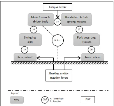
The modelling is based on the multibody mechanical theory [7]. The model developed here is composed of 6 bodies and 11 degrees of freedom (DoF) as shown on Fig. 1. Characterization of suspensions as well as pneumatics force and torque are included respectively in the connections of body concerned. The model has two inputs: the torque applied by the driver on the handlebars and the braking/traction forces. The driver's body is anchored to the frame. Simulation is driven with the scientific software Matlab Simulink/SimMechanics.
Since this software supports only the forces and torque as input, it was necessary to transform the expected (or requested or desired) speed in a positive or negative force applied on the front and rear wheel. A control force proportional to the difference between the setpoint target speed and the speed of the main frame is applied using the equation:
(1)
With the traction force applied on the motorcycle, a constant gain and the difference between the desired and actual speed.
If the speed of the motorcycle is less important than the desired speed, the force applied is positive otherwise negative.
Concerning the tires, the model of Pacejka adapted for motorcycle which accepted large camber angle is used [8]. The university of Delft proposed a module for Matlab Simulink/SimMechanics which was implemented in the global model [9].
The position of the center of gravity, the mass and the inertias of each body comes from the results of an extensive literature review and measurement on the motorcycle [10],[4],[11].
The proposed model takes into account technical and geometrical specificities of the vehicle. These values have been measured on the Honda VFR.
Fig. 1. Multibody model architecture
2.2 Experimental tests and motorcycle instrumentation
The best way to validate a model is to compare results from numerical simulations with data acquired during experimental tests. So, a motorcycle Honda VFR 800 was instrumented in order to achieve experimental tests. The motorcycle is equipped with several sensors to obtain the majority of information needed for the study of the dynamic behaviour of a motorcycle and external forces applied by the driver. All the sensors are listed below :
-The roll angle is determined by using two laser rangefinders on both sides of the motorcycle.
-The speed is measured via Hall Effect sensors which are mounted on each wheel. The installed sensors are the same as those that fit the motorcycle ABS system.
-The braking information is double, an On/Off sensor is wired directly on the brake light but information on the braking intensity was missing, so pressure sensors were integrated into the braking system.
-The roll, yaw and pitch rate, accelerations estimation and GPS position (1Hz) are measured with an Inertial Measurement System (IMU).
-The quantification of suspension travel is doing with laser rangefinders. -The throttle opening is measured with a potentiometer placed on the throttle. -The context is given by a camera placed on the front of the motorcycle.
-The torque applied by the driver on the handlebar and the steering angle are measured with a sensor placed between the handlebar and the steering system.
In all, more than 25 channels are recorded.
The experimental trials are conducted on a closed track and the motorcycle is ridden by an experimented but non-professional driver.
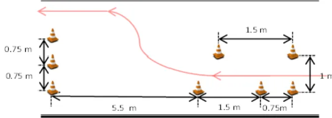
Three kinds of tests were performed: braking, avoidance and slaloms manoeuvres. Each of these tests is conducted at various speed and performed three times. No ISO standard specifying the layout of specific driving situations exists in literature that is why the chosen layout for slalom or avoidance manoeuvre are those defined in the new motorcycle driving test in Europe[12] as show on
Fig. 2. Braking are made at different speed by operating the front or the rear brake or both.
Fig. 2 Slalom and avoidance layout
A total of 69 tests was conducted and distributed as follows: 18 avoidances (on the left and right, at 30 km/h, 40 km/h and maximum speed of about 45 km/h), 18 slaloms (entrance on the left and right, at different speeds 30 km/h, 40 km/h and maximum speed of about 50 km/h) and 33 braking (front brake, rear brake, combined braking, engine braking). More than 1700 data acquired were collected and processed.
3. RESULTS
To validate the model in lateral dynamic, roll and steering angles as well as trajectories of the simulation are compared to results obtain by experimental tests for slalom and avoidance at 30, 40 and 50 km/h on right and left (36 simulations). For braking, comparison between speeds and accelerations acquired and simulated is done to validate in longitudinal dynamic, at 30, 50, 70 and 90 km/h with only rear or front or both brake (33 simulations). Results presented here concern speed at 30 and 50 km/h for slalom and avoidance and 30 and 90 km/h with rear and front brake for braking.
3.1 Avoidance manoeuvres
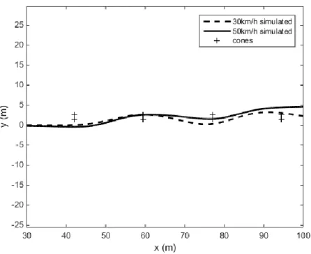
As shown on Fig. 3 at the speed of 30 km/h and 50 km/h the model is able to reproduce the avoidance recorded during experimental test. The two trajectories are compying with the route between the cones. During experimental test it was noticed that for an avoidance at 50 km/h the trajectory is more direct while at 30km/h because the driver had enough time to avoid the cone.
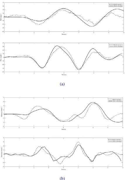
As shown on Fig. 4 the model had a better answer at high speed than at lower speed. At 30 km/h, the entry in the avoidance is similar with data acquired than with data simulated, but in the second part, in exiting, a difference can be noticed. At 50 km/h, the model gives a response in accordance with experimental test. A slight delay can be reported on the results of the simulation with respect to those from the acquisition. For an avoidance at 30km/h, the maximum steering angle acquired is 5° (6° simulated). The maximum steering angle observed during the counter steering phases is about 2°.
It can be noticed that the exit of the avoidance is more stressing than the entry. The maximum roll angle acquired is approximately 20° (22° simulated). On the contrary to steering angle, there is no difference between the two phases of the avoidance concerning the roll angle.
Fig. 3 Avoidance trajectories
(a)
Fig. 4 Roll angle (a) and steering angle (b) for avoidance at 30 and 50 km/h.
For an avoidance at 50 km/h, the maximum steering angle acquired is 3° (4° simulated). Concerning the roll angle acquired and simulated, at 50 km/h, the maximum is 37° and the entry is more stressing that the exit. This can be explain by the fact that the driver is constrained in entry by the layout but not in exit.
3.2 Slalom manoeuvres
Figure 5 shows the simulated trajectories during a slalom at the two speed 30km/h and 50km/h. At the speed of 30 km/h the driver had time to browse the slalom that is why the trajectory is more fluid than at 50 km/h. However at the two speeds the model is able to describe a slalom between cones.
Figure 5 Slalom trajectories.
Fig. 6 gives the roll angle and the steering angle for slalom at 30km/h and 50 km/h obtained with the model and compared with the experimental acquisition. At 30 km/h or 50 km/h the bigger difference is at the exit of the slalom. The roll angle changes are more brutal at 50 km/h. Indeed, the increasing of the speed decrease the time necessary to react. For a slalom at 30 km/h, the maximum steering angle acquired is 5° (6° simulated). The passage of the last cone is more stressing than the others. It can be explained by the fact that the driver accumulates the constraints of each change of phases. Concerning the roll angle, the maximum value acquired is 20° (22° simulated). The last skirt is less stressing, like the first, because they are not complete.
For a slalom at 50 km/h, the maximum steering angle acquired is 6° (4° simulated). Each phases of the slalom is as much stressing as the others. Concerning the roll angle, the maximum value acquired is 30° (32° simulated). The passages of the first and the last cones are less stressing because the driver is not constrained in entry or in exit.
(a)
(b)
Fig. 6 Roll angle (a) and steering angle (b) for slalom at 30 and 50 km/h. 3.3 Braking
Concerning the braking (Erreur ! Source du renvoi introuvable.), according to experimental test, it has been observed that at the speed of 30 km/h the distance necessary to stop the motorcycle is about 4.3 meters and the mean deceleration is 7.8 m/s². At the speed of 50 km/h the braking distance is nearly tripled and is about 11.4 meters for a deceleration of 7.7 m/s². At the speed of 70 km/h the distance necessary to stop the motorcycle is 18.6 meters and the deceleration is 7.4 m/s². Finally at the speed of 90 km/h, the braking distance is 24.6 meters and the deceleration is 6.5 m/s².
4. CONCLUDING REMARKS
A multi body model which can simulate emergency driving situations have been developed and compared with experimental tests. Globally, the multi body model have dynamical responses in accordance with the real acquisition both in longitudinal and in transversal solicitations. For slalom and avoidance the model is valid between 30 and
50 km/h, and for braking between 30 and 90 km/h. These ranges of speed match the majority of cases that can be encountered on the road. Indeed, previous study have shown that accident occur at an average speed of 37 km/h [13].
Some improvement can be made on the model, especially in consideration of the driver. A driver model should be developed to take better into account his movement on the motorcycle. But in order to develop a driver model, additional sensors should be install on the instrumented motorcycle to record the roll torque applied by the body of the driver in addition of the steering torque on the handlebar.
Future work will concern the application of the numerical model to real accidents reconstructions involving PTW. Based on parametric studies, the objective is to determine the most probable accident configuration from inputs driver variations. Particular attention will be paid to PTW loss of control since they appear as situations more complex to understand.
5. REFERENCES
[1] Observatoire national interministériel de la sécurité routière, “L’accidentalité routière en 2014.” La documentation Française.
[2] K. S. Obenski, P. F. Hill, E. S. Shapiro, and J. C. Debes, Motorcycle Accident Reconstruction and Litigation. 1994.
[3] R. S. Sharp and D. J. Limebeer, “A motorcycle model for stability and control analysis,” Multibody Syst. Dyn., vol. 6, no. 2, pp. 123–142, 2001.
[4] R. S. Sharp, S. Evangelou, and D. J. Limebeer, “Advances in the modelling of motorcycle dynamics,” Multibody Syst. Dyn., vol. 12, no. 3, pp. 251–283, 2004. [5] V. Cossalter and R. Lot, “A Motorcycle Multi-Body Model for Real Time
Simulations Based on the Natural Coordinates Approach,” Veh. Syst. Dyn., vol. 37, no. 6, pp. 423–447, 2002.
[6] H. Nasser and N. K. M’Sirdi, “Decoupled model for motorcycle and identification of dynamic parameters,” in 2012 IEEE/ASME International Conference on Mechatronics and Embedded Systems and Applications (MESA), 2012, pp. 142–147.
[7] A. Shabana, Dynamics of Multibody Systems. Cambridge University Press, 2003. [8] H. Pacejka, Tire and Vehicle Dynamics. Elsevier, 2005.
[9] “Delft-Tyre - MF-tyre/MF-Swift,” TASS International, 07-Jan-2013. [Online]. Available: https://www.tassinternational.com/delft-tyre-mf-tyremf-swift. [Accessed: 28-Nov-2016].
[10] W. D. Versteden, “Improving a tyre model for motorcycle simulations,” TU Eindh. Rep. DCT, vol. 2005, 2005.
[11] S. Evangelou, “Control and Stability Analysis of Two-wheeled Road Vehicles,” University of London, 2004.
[12]Arrêté du 10 janvier 2013 modifiant l’arrêté du 23 avril 2012 fixant les modalités pratiques de l’examen du permis de conduire des catégories A1, A2 et A. .
[13] T. Serre, C. Masson, C. Perrin, J.-L. Martin, A. Moskal, and M. Llari, “The motorcyclist impact against a light vehicle: Epidemiological, accidentological and biomechanic analysis,” Accid. Anal. Prev., vol. 49, pp. 223–228, Nov. 2012.