RESEARCH OUTPUTS / RÉSULTATS DE RECHERCHE
Author(s) - Auteur(s) :
Publication date - Date de publication :
Permanent link - Permalien :
Rights / License - Licence de droit d’auteur :
Bibliothèque Universitaire Moretus Plantin
Institutional Repository - Research Portal
Dépôt Institutionnel - Portail de la Recherche
researchportal.unamur.be
University of Namur
Deriving User-Requirements From Human-Computer Interfaces
Brogneaux, Anne-France; Ramdoyal, Ravi; Vilz, Julien; Hainaut, Jean-Luc
Published in:
Proc. of 23th IASTED DBA 2005 Conf.
Publication date:
2005
Link to publication
Citation for pulished version (HARVARD):
Brogneaux, A-F, Ramdoyal, R, Vilz, J & Hainaut, J-L 2005, Deriving User-Requirements From Human-Computer Interfaces. in Proc. of 23th IASTED DBA 2005 Conf.. ACTA Press, pp. 77-82.
General rights
Copyright and moral rights for the publications made accessible in the public portal are retained by the authors and/or other copyright owners and it is a condition of accessing publications that users recognise and abide by the legal requirements associated with these rights. • Users may download and print one copy of any publication from the public portal for the purpose of private study or research. • You may not further distribute the material or use it for any profit-making activity or commercial gain
• You may freely distribute the URL identifying the publication in the public portal ? Take down policy
If you believe that this document breaches copyright please contact us providing details, and we will remove access to the work immediately and investigate your claim.
Deriving User-requirements
From Human-Computer Interfaces
Anne-France Brogneaux, Ravi Ramdoyal, Julien Vilz, Jean-Luc Hainaut Laboratory of Database Application Engineering
University of Namur (FUNDP) Rue Grandgagnage 21 B-5000 Namur (Belgium) {afb,rra,jvi,jlh}@info.fundp.ac.be
ABSTRACT
In this paper we explore the possibility of designing components of information systems by optimally exploiting the information explicitly or implicitly in human-computer interfaces. In this process it is assumed that the end-user, with minimal training, is able to sketch a prototype interface of the future application, from which the conceptual model of the application domain can be derived semi-automatically. In particular, the information contents of the electronic forms can be extracted and conceptualised through reverse engineering and integration techniques to significantly contribute to the conceptual schema of the future database.
KEYWORDS
Database Design, Graphical User Interfaces, Software Requirements, End-user, CASE Tool.
1. Introduction
Using prototypes is one of the most efficient elicitation techniques. This particular method is useful when there are doubts about the goals of the future application, and when user opinions are needed early in the design process [1]. Prototype elaboration in the requirement analysis phase is obviously expensive : it includes the development of a limited but operational application, whose components are usually not reusable for the implementation of the final system.
The comprehension of user interfaces has improved in organisations thanks to the increasing use and training level in the field of information technologies. From this observation, we can assume that users are now quite familiar with GUI and that many of them should be able to draw the prototype of the interface of the future application. This prototype brings essential information particularly in two domains, namely the static objects of the application domain and the users tasks.
It is therefore possible to involve end-users more actively in the expression of their needs by allowing them to build the interface of the future application in terms of command screens and information exchanges. A task and functionality model as well as an underlying information model can be derived from these components.
This paper mainly concentrates on the problem of extracting static objects specification from this prototype interface, that is, designing the conceptual schema of the database, or at least contributing to this design through user interface analysis. It relies on three principles that we will consider to be hypotheses due to the limited scope of this paper:
1. from the user perspective, forms, and more specifically electronic forms, are more natural and intuitive than usual conceptual formalisms as far as expressing information requirements is concerned;
2. a form comprises data structures that can be seen as a particular view on the conceptual schema of the database; 3. a form is a physical implementation of a part of the conceptual schema, so that database reverse engineering techniques can be applied to recover that part of this schema.
The proposed approach consists in letting users draw the interface with the application in project that most suit their needs, then in analysing the information contents of the resulting dialog boxes and forms in order to extract the underlying information structures. From the latter, a conceptual schema is progressively built and validated Although this approach does not entirely replace more traditional task and information analysis approaches, it nevertheless allows to grab more efficiently and more reliably a substantial part of the initial specifications. The method we describe in this article addresses the analysis and development of databases. In order to decrease costs while increasing the quality of the requirements analysis phase, it provides designers and end
users with tools that make conceptual schema design easier.
Extracting and modelling the behavioural aspects of the target application through interface analysis will not be addressed in this paper.
The paper is organised in two main parts : the first one describes the approach in its theoretical aspects as follows and the second one illustrates this approach with a small case study.
This method is being developed within the context of the ReQuest project, whose objective is the creation of intelligent tools for web-based application development.
2. The approach
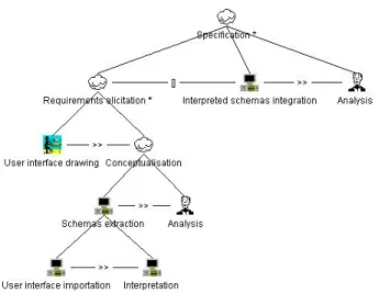
The tasks of the approach are illustrated in Figure 1 using the ConcurTaskTree notation [2]. Other elicitation techniques, such as natural language analysis and interviews have been ignored for simplicity.
Figure 1 : Conceptual schema extraction
The main task (Specification), whose aim is the elaboration of the conceptual schema for the application domain, is divided in sub-tasks. The first one is the requirements elicitation, which includes two main steps, namely interface drawing, by end users, and conceptualisation.
The user is provided with a collection of WYSIWYG tools for interface drawing. According to the skill of the user, several tools are available, ranging from freehand sketching tool on a tablet PC, providing fast and easy, but low-fidelity, results, to comprehensive interface builders, whose result will be used almost unchanged to develop
the operational system (high-fidelity prototype). The user, who is given a short training, is able to build the interface (screens, dialog boxes, forms, web pages) he thinks the most appropriate according to the application’s functions. Two extreme scenarios are considered for this task: • the task is performed by the user alone, provided he
masters the drawing tools and elementary rules of interface building;
• the task is performed jointly by the user and an experienced designer who translate users requirements into user interface.
Other intermediate patterns can be defined according to the skill of the end users in interface building and the availability of experienced designers.
According to the semiotic approach of user interface design [3], a user interface is considered to be a complex message exchange between the system and the user. In order to identify the concepts manipulated by the future application, we have to identify the semantic of these messages; this is the aim of the “conceptualisation” task. Messages are composed of signs, that, in the field of graphical user interface, are widgets. Though some of them are highly expressive and therefore bring much semantics, the user will often be invited to add interpretation annotation to allow a more complete conceptualisation.
The concepts conveyed by screens and forms are abstract entities that belong to the mental model of the user. These entities are represented in a standard model [3], namely a variant of the Entity Relationship (ERA) model. Raw diagrams representing data structures are built through the “user interfaces importation” sub-task. They give a neutral representation of the underlying data structures but are still uninterpreted so far.
The “Interpretation” sub-task allows the analyst to determine the domain concepts from each of the raw diagrams, to identify and solve the gaps and incoherence among the concepts. The analyst will correct and refine the user interfaces with the collaboration of the user. This process is iterative by nature.
The diagrams produced by the interpretation of interfaces are integrated to form a global schema of the application concepts after that have been fully validated by the user and the analyst
At this stage, the intervention of the user will often be required in order to complete the specifications and to clear any remaining ambiguities.
2.1. Interfaces drawing
In the proposed approach, descriptions of interfaces is a major source of information for conceptualisation. These descriptions are exploited in two ways. On the one hand, they are analysed to extract a conceptual schema of a future database, and on the other hand they are used to generate the real application user interface according to the target technology. The description format has to follow a strict syntax independent of any operational user interface manager tools. This latter property makes it possible to use code generator for many languages and graphical user interface libraries.
In the context of the Request project, the USIXML language [4] meets these characteristics, while the GrafiXML WYSIWYG tool [5] enables the drawing of user interfaces, which are specified using this language. The user is instructed to use simple and intuitive coherence rules while designing the interfaces. Some important rules suggest:
• to assign an expressive label to each control and to place it at one from definite positions;
• to group into a common frame fields that relate to a same concept;
• to assign the same label to all the controls referring to the same concept (as few synonyms as possible); • to assign different labels to controls that refer to
different concept (as few homonyms as possible); These rules may not always be followed because of ergonomic reasons (the user may wish not to assign an explicit label to a control that doesn’t require one) or in case of ambiguities (a customer and a supplier both have an address, but these addresses do not represent the same concept). In this case, the user can annotate the control and assign to it an invisible label, possibly with the help of the analyst. We therefore dissociate the visible interface label from the invisible semantic label.
2.2. Interfaces importation
Several approaches have explored the existing link between user interface and application domain conceptual schema both in forward engineering [6][7][15]and in reverse-engineering [8]. The “user interface importation” task is one of them. It takes in consideration the graphical user interface evolution and its ergonomics.
“It is necessary to understand the semantics of each control in its different uses in order to be able to transform user interfaces into a semantic data model” [7]. For this purpose we use the ergonomic rules mentioned in [9].
Some of these rules allow to choose the right control according to the context. As an example, an ergonomic rule recommends to use a group box containing checkboxes to represent a choice among four to seven known alphanumeric values.
A set of rules determine patterns for using controls. To each pattern derived from common ergonomic rules, we have associated a conceptual representation. The previous example is represented by a multivalued attribute drawing its name from that of the group box whose value domain is determined by the checkboxes labels. A pattern matching mechanism using these rules automatically transforms XML interface descriptions into ERA uninterpreted raw diagram
Some patterns require the use of additional annotations when the user interface structure is not sufficient for the semantic extraction. Metaphorical display is one of these patterns. It uses a real world representation to facilitate the user task. Annotations are required to help the interface importer to understand those metaphors.
For example: “business , accountancy and massive data acquisition applications can use the filling-the-blank metaphor” [9]. In this metaphor, the concept of label has no meaning. The semantic for the user proceeds from the whole sentence containing the blanks. The interfaces importation tools require invisible label for each blank. In the Figure 2 these labels could be “Beginning of license validity period” and “Ending of license validity period”.
2.3. Interpretation
The interpretation task consists in identifying the relevant concept of the application domain in the uninterpreted schema.
We consider a concept to be potentially relevant if it shows some degree of structural complexity : a concept can for instance be represented by an entity type (deriving from an interface screen) or a compound attribute (group box or table). It is important to distinguish the structures forming a local complex property of the object described by the window from the structures referring to relevant concepts external to this object. As in the conceptualisation process in the reverse engineering method described in [12], this distinction highly depends on the semantics and on the application domain. The user intervention is hence often necessary.
License valid from __/__/____ to __/__/____
For example, a customer address and customer orders can both be represented by multivalued compound attribute structure. After further analysis, it may appear that, • the address complex attribute is interpreted as a local
customer property,
• the orders complex attribute is interpreted as an external concept that must appear in other interfaces. The interpretation then consists in representing the identified concepts by entity types according to the rules established in the section 2.1. A compound attribute that appears as a compound attribute or an entity type in another interfaces is extracted as an autonomous entity type according to the transformational approach [10]. The entity types are named by their invisible label if it exists, or by their visible label otherwise.
The gaps and incoherence of the schemas provided to the analyst by this automatic phases are highlighted. The analyst completes and corrects the schema by discussing with the user in order to deal with two aspects. The first one is the semantic of the link between the new extracted concept and the interface from which it is derived. This link is documented in the schema by giving a name to the corresponding relationship type. It must be stated that the association types characteristics are not complete at this stage, as one of the two cardinalities is still undefined. It will however be set during the integration phase. The second aspect is the relative identification of the concepts in relation to the interface (for example, can a same product number appear several times in an order form?). These interpreted schemas modifications are reflected in the interfaces by addition of semantic annotations, and a new version of the schemas is generated from these supplemented interfaces. After several iterations of the Requirements elicitation task (Figure 1), the annotated interfaces constitute the complete and non ambiguous documentation of the concepts manipulated by the future application. A database could therefore automatically be generated from this documentation.
2.4. Interpreted schemas Integration
The user-validated schemas are integrated to form a conceptual schema representing the specification of the
requirements expressed by the user through the interfaces. This specification should be formal, complete, minimal, unambiguous, abstract and readable. The domain concepts and their internal links have been univocally represented by similarly named objects throughout the extracted and interpreted schemas. The concepts are represented by entity types while the links between them are represented by relationship types. The integration of these objects can be, to a large extent, automated given the interface-derived partial schemas preparation.
During this phase, relationship types characteristics are refined. For instance, let us assume that an order can be associated with several invoices in a given interpreted schema, and that an invoice corresponds to one and only one order in another given interpreted schema. The two semantically similar relationship types will be integrated into a single relationship type whose cardinalities are clearly defined : an order is associated with several invoices and an invoice corresponds to one and only one order. There is a one-to-many relationship type from order to invoice in the integrated schema
The analyst jointly works with the user following this automatic phase, in order to fill any remaining gaps left undetected or unresolved by previous phases. It usually mainly addresses absolute identifiers and cardinalities definition issues. These modifications will also be reflected on the interfaces thanks to annotations.
The integration rules adopted follows those which have been proposed in the database field [13] [14]. However, they also have to cope with incomplete specifications, so that conflict-solving rules have been adapted.
3. Case Study
This short illustration concerns the organisation of training courses. We will show how the first three steps of the proposed approach apply.
The user draws the prototype of two windows that are considered necessary and sufficient to deal with the part of the future system that records and manage the courses. The “Session” window gathers information on a particular course session, knowing that each course can be given several times. A session is split into modules which each has its own window. Each “Module” window allows the user to collect precise information on these modules, such as the teacher names.
3.2. Interfaces importation
The information contents of each window is abstracted according to the ERA model by applying pattern matching rules. Technically, the windows drawn by the user in the GrafiXML tool are exported in a USIXML document. This document is then imported and interpreted by the DB-MAIN CASE tool[11] to produce an ERA schema. The “Session” window is represented by an entity type with the name “Session”. The group boxes (“Fare”, “Course”, “Module”) are represented by compound attributes. A group box comprising several fields is translated as a single-valued attribute, while a group box containing one and only one table translates into a multivalued attribute, whose sub-attributes are given by the table columns. The edit boxes (“Number”, “Date”, “Number of days”, “Name”, “Language”, “Date”) are
represented by atomic single-valued attributes named by the corresponding identifying label.
3.3. Interpretation
The relevant concepts (as defined in section 2.3) are then transformed into entity types. This transformation is automatic as the documentation obtained during the Interfaces importation task is complete and non ambiguous. In this case the relevant concepts are the compound attributes “Module” in the “Session” entity type, “Course” in the “Session” and “Module” entity types, and “Session” in the “Module” entity type. They are thus transformed into entity types using DB-MAIN. After this transformation, the analyst has to detect missing information such as the new relationship types semantics and the cardinalities of the new roles of entity types. For instance, the relationship type between entity types “Session” and “Module” and the cardinality of the “Module” role must be defined. Following a discussion with the end user, the interface is enriched with annotations that add the acquired information, and the sub-schemas are finally validated. In particular, the relationship type between “Session” and “Module” is named “composition”. The unknown cardinalities, shown in bold in Figure 3, stay unchanged because some of them
Figure 3 – Case Study
SESSION Number Date Number of days Course Name Language Date Fare[0-N] Status Rate Module[0-N] Date Begin End MODULE Date Begin End Teacher[0-N] Session Number Course Name Language Date
Importation Interpretation and analysis Interface drawing ? 0-N 1-1 of ? 0-N 0-N composition SESSION Number Date Number of days Fare[0-N] Status Rate MODULE Date Begin End COURSE Name Language Date ? 0-N 1-1 of ? 0-N 1-1 composition SESSION Number MODULE Date Begin End Teacher[0-N] COURSE Name Language Date
will automatically be resolved during the integration phase.
3.4. Interpreted schemas Integration
The integration process follows the pre-integration approach, according to which a pre-integration step resolves all the conflicts that may arise during final schema merging.
Since the sub-schemas have been prepared in order to univocally name (no homonymy, no synonymy) and each concept has been semantically validated, the final phase is thus automatic. We hence obtain a tentative conceptual schema of the application domain. The missing information that has not been resolved during the previous tasks is shown in bold in the results of the integration step (Figure 4). In this case, the analyst validates the proposed cardinality 0-N representing the number of sessions for a course by asking the user. The figure 4 shows the final conceptual schema.
4. Method extension
We can achieve two more tasks from the complete screen specification and the final conceptual schema, namely the design of the database and some procedural components of the future application.
4.1. Database Design
The database is designed from the conceptual schema using the traditional approach based on transformational techniques. The traceability is ensured through the transformation history that is recorded and maintained during the whole process, in order to allow instant association between interface components and database objects. This history allows an automatic SQL queries generation to fill the user interfaces with existing data.
4.2. Procedural Components Conception
The natural business objects can also be derived by analysing similarities between interface interpreted sub-schemas. We then obtain object schemas from which we can automatically generate object classes code, including constructors, accessor and modifier methods, as well as ready-to-implement processing methods frameworks. In order to implement the latter, business rules must be taken in account (this part of the project still is unexplored.). The connection between interface components and database objects will be ensured by the obtained business objects.
5. Conclusion
The results of our approach allowed defining and extracting the necessary information contained in user defined interfaces in order to create the application domain conceptual schema as well as important software components. The application domain model is not sufficient however to elaborate a complete information system. Other aspects must be taken in account as in standard analysis approaches.
From a practical point of view, some tools have been developed in DB-MAIN to evaluate our approach : an interface importation tool, a schema interpreter, a schema integrator and a queries generator.
The extension of our method consists in analysing the information included in human-computer interfaces and useful for designing enterprises organisation models, data models, functional and non-functional models. The method available backtracking enables to highlight existing links between the models, and for instance to generate database queries based on the functional and the data models.
References
[1] B. Nuseibeh & S. Easterbrook, Requirements Engineering: A Roadmap, in The future of software
engineering, ACM Press, New York, 2000, 37-46.
Figure 4 - Integrated Conceptual Schema before analysis 1-1 ? 0-N of 0-N 1-1 composition SESSION Number Date Number of days Fare[0-N] Status Rate MODULE Date Begin End Teacher[0-N] COURSE Name Language Date
[2] G. Mori, F. Paternò & C. Santoro., CTTE: Support for Developing and Analyzing Task Models for Interactive System Design, in IEEE Transactions on
Software Engineering, August 2002, 797-813.
[3] J.C. Leite, A semiotic-based framework to user interface design, in Proc. of the second Nordic
conference on Human-computer interaction, 2002,
263-265.
[4] Q. Limbourg,, J. Vanderdonckt, B. Michotte, L. Bouillon, M. Florins, & D. Trevisan, USIXML: A User Interface Description Language for Context-Sensitive User Interfaces, in Developing User
Interfaces with XML: Advances on User Interface Description Languages, Workshop at AVI04, May
2004.
[5] The GrafiXML interface drawing tool website: http://www.usixml.org/index.php?page=grafixml.xml [6] J. Choobineh, M.V. Mannino & V.P. Tseng, A
Form-Based Approach for Database Analysis and Design,
In Communications of the ACM, vol. 35, n°2, February 1992, 108-120.
[7] S.R. Rollinson & S.A. Roberts., Formalizing the Informational Content of Database User Interfaces, In Conceptual Modeling - ER'98, In Proceedings of the
17th International Conference on Conceptual Modelling, Springer-Verlag, 1998, 65-77.
[8] L. Heeseok & Y. Cheonsoo., A form driven object-oriented reverse engineering methodology, in
Information Systems, vol. 25, n°3, 2000, 235-269.
[9] J. Vanderdonckt, Guide ergonomique des interfaces
homme-machine, Presses Universitaires de Namur,
1994.
[10] J.-L. Hainaut, Entity-generating Schema Transforma-tions for Entity-RelaTransforma-tionship Models, in Proc. of the
10th Entity-Relationship Approach, San Mateo (CA),
North-Holland, 1991, 643-670.
[11] V. Englebert, J. Henrard, J.-M. Hick, D. Roland, J.-L. Hainaut, DB-MAIN : un atelier d'ingénierie de bases
de données, Ingénierie des Systèmes d'Information,
Vol. 4, No. 1, Hermes - AFCET, 1996.
[12] J.-L. Hainaut, C. Tonneau, M. Joris, M. Chandelon, Schema Transformation Techniques for Database Reverse Engineering, in Proc. 12th Int. Conf. on
Entity-Relationship Approach, Arlington-Dallas, E/R
Institute Publish., 1993.
[13] S. Spaccapietra, C. Parent, Y. Dupont, Model Independent Assertions for Integration of Heterogeneous Schemas, in VLD Journal, 1, 1992, 81-126.
[14] C. Batini, S. Ceri, S. Navathe, Conceptual Database
Design – An Entity Relationship Approach
(Benjamin-Cummings 1992)
[15] K-D Schewe, B. Schewe, Integrated database and dialogue design, in Knowledge and Information
![Figure 4 - Integrated Conceptual Schema before analysis1-1 ? 0-Nof0-N1-1compositionSESSIONNumberDateNumber of daysFare[0-N]StatusRateMODULEDateBeginEndTeacher[0-N] COURSEName LanguageDate](https://thumb-eu.123doks.com/thumbv2/123doknet/14570703.727574/7.918.155.373.128.452/integrated-conceptual-analysis-compositionsessionnumberdatenumber-daysfare-statusratemoduledatebeginendteacher-coursename-languagedate.webp)