HAL Id: tel-01002113
https://tel.archives-ouvertes.fr/tel-01002113
Submitted on 5 Jun 2014HAL is a multi-disciplinary open access archive for the deposit and dissemination of sci-entific research documents, whether they are pub-lished or not. The documents may come from teaching and research institutions in France or abroad, or from public or private research centers.
L’archive ouverte pluridisciplinaire HAL, est destinée au dépôt et à la diffusion de documents scientifiques de niveau recherche, publiés ou non, émanant des établissements d’enseignement et de recherche français ou étrangers, des laboratoires publics ou privés.
Modeling, simulation and control of the air-path of an
internal combustion engine
Fayez-Shakil Ahmed
To cite this version:
Fayez-Shakil Ahmed. Modeling, simulation and control of the air-path of an internal combustion engine. Other [cond-mat.other]. Université de Technologie de Belfort-Montbeliard, 2013. English. �NNT : 2013BELF0203�. �tel-01002113�
Thèse de Doctorat
n
é c o l e d o c t o r a l e s c i e n c e s p o u r l ’ i n g é n i e u r e t m i c r o t e c h n i q u e s
U N I V E R S I T É D E T E C H N O L O G I E B E L F O R T - M O N T B É L I A R D
Modeling, simulation and control of
the air-path of an internal
combustion engine
Mod ´elisation, simulation et
commande de la boucle d’air d’un
moteur `a combustion interne
Thèse de Doctorat
é c o l e d o c t o r a l e s c i e n c e s p o u r l ’ i n g é n i e u r e t m i c r o t e c h n i q u e s
U N I V E R S I T É D E T E C H N O L O G I E B E L F O R T - M O N T B É L I A R D
TH `
ESE pr ´esent ´ee par
Fayez Shakil
A
HMED
pour obtenir le
Grade de Docteur de
l’Universit ´e de Technologie de Belfort-Montb ´eliard
Sp ´ecialit ´e :Automatique
Modeling, simulation and control of the air-path of an
internal combustion engine
Mod ´elisation, simulation et commande de la boucle
d’air d’un moteur `a combustion interne
Soutenue le 04 Juillet 2013 devant le Jury :
Pr. Didier MAQUIN Pr ´esident Universit ´e de Lorraine
Pr. EricBIDEAUX Rapporteur Universit ´e INSA de Lyon
Pr. RachidOUTBIB Rapporteur Universit ´e d’Aix-Marseille
M. DavidGUYON Examinateur SOGEFI syst `emes moteur SAS
Pr. Maurizio CIRRINCIONE Examinateur Universit ´e de Technologie de
Belfort-Montb ´eliard
Pr. Mohammed EL BAGDOURI Directeur de th `ese Universit ´e de Technologie de
Belfort-Montb ´eliard
Dr. Salah LAGHROUCHE Co-Directeur Universit ´e de Technologie de
Belfort-Montb ´eliard
List of publications
Peer-reviewed journal papers
F.S. Ahmed, S. Laghrouche, M. El Bagdouri Overview of the modelling techniques of actuator non-linearities in the engine air path Proceedings of the Institution of Me-chanical Engineers, Part D: Journal of Automobile Engineering , Vol 227 Number 3, pp 443-454, 2012.
M. Harmouche, S. Laghrouche, F.S. Ahmed, M. El Bagdouri Second-order sliding mode controllers: an experimental comparative study on a mechatronic actuator Proceed-ings of the Institution of Mechanical Engineers, Part I: Journal of Systems and Control Engineering, Vol 226, Number 9, pp 1231-1248, 2012.
F. S. Ahmed, S. Laghrouche, M. El Bagdouri Analysis, modeling, identification and control of pancake DC torque motors: Application to automobile air path actuators, Mechatronics, Vol 22, Issue 2, pp 195-212, 2012.
Peer-reviewed international conference papers
F. S. Ahmed, S. Laghrouche, M. El Bagdouri. Cascaded Second order sliding mode observer for state and friction dynamics of a control valve, The 12th International Workshop on Variable Structure Systems 2012, Mumbai India, pp. 94-99.
F. S. Ahmed, S. Laghrouche, M. El Bagdouri. State observation and friction estimation in engine air path actuator using higher order sliding mode observers, 18th IFAC World Congress 2011, Milan Italy, Vol. 18, Issue 1, pp. 7480-7485.
ii LIST OF PUBLICATIONS
F. S. Ahmed, S. Laghrouche, M. El Bagdouri. An experimental comparative study of different second order sliding mode algorithms on a mechatronic actuator, American Control Conference 2011, San Francisco USA, pp. 5286-5291.
F. S. Ahmed, S. Laghrouche, M. El Bagdouri. Second-Order Sliding Mode based Output-Feedback Control of an Engine Air Path Actuator in presence of uncertainties, Con-ference on Control and Fault-Tolerant Systems 2010, Nice France, pp. 50-56. F. S. Ahmed, S. Laghrouche, M. El Bagdouri. Pancake Type DC Limited Angle Torque
Motor: Modeling and Identification, Application to Automobile Air Path Actuators, 6th IFAC Symposium: Advances in Automotive Control 2010, Munich Germany, pp. 431-436.
S. Laghrouche, F.S. Ahmed, M. El Bagdouri. Modeling and Identification of a Mecha-tronic Exhaust Gas Recirculation Actuator of an Internal Combustion Engine, Amer-ican Control Conference 2010, Baltimore USA, pp. 2242-2247.
F. S. Ahmed, S. Laghrouche, M. El Bagdouri. Nonlinear modeling of Pancake DC Lim-ited Angle Torque Motor based on LuGre friction mode, IEEE Vehicle Power and Propulsion Conference 2010, Lille France, pp. 1-6.
Contents
List of publications i Contents iii List of Figures ix Acknowledgement xv Introduction 10.1 Diesel Engine Air-path . . . 3
0.1.1 Pressure Boosting (Turbocharging) . . . 4
0.1.2 Exhaust Gas Recirculation . . . 5
0.2 Air-path Subsystems . . . 6
0.2.1 Variable Geometry Turbocharger (VGT) . . . 6
0.2.1.1 VGT actuator . . . 6
0.2.2 EGR Valve . . . 7
0.2.3 Cooling Systems . . . 7
0.2.4 Swirl actuators . . . 7
0.3 Problems and contributions . . . 8
0.3.1 System Modeling . . . 11 0.3.2 Actuator Modeling . . . 11 0.3.3 Actuator control . . . 11 0.4 Thesis Structure . . . 12 1 Airpath Modeling 15 iii
iv CONTENTS
1.1 Introduction to Engine and Air-path Modeling . . . 15
1.1.1 Mean Value Models . . . 16
1.1.2 Discrete Event Models . . . 16
1.1.3 Chapter Objectives and Goals . . . 17
1.2 Engine Combustion . . . 18
1.2.1 State of the art . . . 19
1.2.1.1 Zero-dimensional model . . . 19
1.2.1.2 Models based on fluid dynamics . . . 19
1.2.1.3 Phenomenological models . . . 19
1.2.2 Lebas’ Phenomenological Model . . . 20
1.3 Engine Intake . . . 21
1.4 Engine Exhaust . . . 21
1.5 Exhaust Gas Recirculation . . . 21
1.6 Variable Geometry Turbocharger . . . 23
1.6.1 Turbocharger mass-flow maps and correction . . . 23
1.6.2 Compressor Power . . . 25
1.6.3 Turbine Power . . . 26
1.6.4 Turbocharger Speed . . . 26
1.7 Simulator Implementation in AMESim . . . 27
1.7.1 Cylinder and Combustion . . . 27
1.7.2 Intake and Exhaust Manifolds . . . 29
1.7.3 Exhaust Gas Recirculation . . . 29
1.7.4 Variable Geometry Turbine . . . 29
1.7.4.1 Turbine . . . 30 1.7.4.2 Compressor . . . 31 1.7.4.3 Inertial shaft . . . 31 1.7.5 Fuel Injection . . . 31 1.7.6 Auxiliary components . . . 32 1.8 Summary . . . 32 2 Actuator Modeling 33 2.1 Actuator Terminology . . . 34
2.2 Major Actuator Families . . . 36
CONTENTS v
2.2.2 Torque Motor based actuators . . . 38
2.2.2.1 Working Principle . . . 39 2.3 Actuator Modeling . . . 43 2.3.1 PMDC Motor-Spring Systems . . . 47 2.3.2 Torque Motor . . . 50 2.3.3 Friction . . . 51 2.3.3.1 Effects of friction . . . 52 2.3.3.2 Friction Modeling . . . 56 2.3.3.3 Comparison . . . 57 2.3.4 Temperature variation . . . 58 2.3.5 Complete Model . . . 58
2.3.5.1 Extension to Double Action Actuators . . . 60
2.3.6 Actuator Implementation in AMESim . . . 60
2.4 Experimental Validation . . . 61
2.4.1 Parameter Identification . . . 62
2.4.2 Validation . . . 64
2.5 Aging . . . 64
2.5.1 Wear . . . 65
2.5.2 Clogging (Surface deterioration) . . . 65
2.5.3 Torque deterioration (Degradation of motor electrical characteristics) 66 2.6 Summary . . . 67
3 Simulation and Validation 69 3.1 Industrial Test Bench . . . 70
3.2 Air-path Controller . . . 72
3.2.1 Torque Reference Unit . . . 72
3.2.2 Fuel Injection Unit . . . 74
3.2.3 VGT Control Unit . . . 74
3.2.4 EGR Control Unit . . . 76
3.3 Simulation and Validation Results . . . 78
3.3.1 Boost Simulation . . . 79
3.3.1.1 Validation . . . 80
3.3.2 EGR Simulation and Validation . . . 82
vi CONTENTS
4 Specialized Actuator Control 85
4.1 Introduction . . . 85
4.2 Experimental Setup . . . 87
4.3 Sliding Mode based Robust Control . . . 87
4.3.1 Actuator Model with Parametric and Load uncertainty . . . 88
4.3.2 Sliding Mode Control . . . 89
4.3.2.1 Twisting Algorithm . . . 91
4.3.2.2 Super twisting Algorithm . . . 92
4.3.2.3 Quasi-Continuous Algorithm . . . 93 4.3.2.4 Robust Differentiator . . . 94 4.3.3 Control Design . . . 95 4.3.3.1 Sliding Variables . . . 96 4.3.3.2 Feedback Linearization . . . 97 4.3.3.3 Controller Parameters . . . 98 4.3.4 Simulation . . . 99 4.3.4.1 Test Trajectory . . . 100 4.3.4.2 Simulation Results . . . 100 4.3.5 Experimental results . . . 102 4.3.5.1 Nominal Conditions . . . 102 4.3.5.2 Temperature tests . . . 103 4.3.5.3 Sinusoid tests . . . 107
4.3.6 Conclusion on sliding mode controllers . . . 107
4.4 Backstepping Based Adaptive Output Feedback Controller . . . 107
4.4.1 Problem Formulation . . . 109
4.4.1.1 Control problem formulation . . . 110
4.4.2 State Estimation . . . 111
4.4.2.1 Velocity Estimator . . . 112
4.4.2.2 Current observer . . . 112
4.4.3 Controller Design . . . 113
4.4.4 Lyapunov Analysis . . . 115
4.4.5 Simulation and Experiments . . . 119
4.4.5.1 Simulation results . . . 119
4.4.5.2 Experimental results . . . 120
CONTENTS vii
5 VGT Aerodynamic Force Modeling 135
5.1 Mechanism and Notations . . . 136
5.2 One dimensional CFD model . . . 138
5.2.1 Hypothesis and problem formulation with Navier-Stokes equations . 138 5.2.2 Model derivation . . . 140
5.2.3 Source terms . . . 144
5.2.3.1 Geometry of the flow-path . . . 144
5.2.3.2 Evaluation of the output angle . . . 145
5.2.3.3 Blade source terms . . . 146
5.2.3.4 Pressure losses . . . 148
5.2.3.5 Friction source terms . . . 150
5.3 Numeric resolution of 1D Navier Stokes Equations . . . 151
5.3.1 Numerical Resolution . . . 153
5.3.1.1 Explicit method . . . 154
5.3.1.2 Implicit method . . . 154
5.4 Calculation of aerodynamic force on the actuator . . . 156
5.4.1 Relation between crank handle angle and actuator position . . . 157
5.4.2 Relation between crank handle angle and lever direction . . . 159
5.4.3 Relation between the levers and unison ring . . . 159
5.4.3.1 Total torque on the rim . . . 159
5.4.3.2 Net torque on the crank handle . . . 160
5.4.4 Angle between the Crank Handle and Actuator Shaft . . . 161
5.5 Model validation . . . 161
5.6 Summary . . . 163
Conclusion and Perspectives 167 Appendices 173 A Tables . . . 173
B Torque and friction characteristics comparison . . . 174
C Sensors and transmission protocol in actuators . . . 176
D LaSalle Yoshizawa Theorem . . . 178
E Calculation of upper time bound of URED . . . 179
List of Figures
Figure 0.1. Evolution of European Emission standards . . . 2
Figure 0.2. Engine air-path . . . 4
Figure 0.3. Mechanical diagram of a variable geometry turbocharger . . . 7
Figure 0.4. VGT with an electro-pneumatic actuator system . . . 8
Figure 0.5. EGR actuator . . . 9
Figure 0.6. Double air mixer . . . 9
Figure 0.7. Inlet swirl actuator . . . 10
Figure 1.1. Air-path variables and airflow. Variables: p =pressure,T =temperature, ˙ m =mass flow. Subscripts: i =intake manifold,e =exhaust manifold, T =Turbine, c =compressor, f=fuel, α =cylinder, at m =atmosphere, eg r =EGR . . . 18
Figure 1.2. Mass flow and pressure difference of EGR Valve at different openings 22 Figure 1.3. Mechanical diagram of a variable geometry turbocharger . . . 23
Figure 1.4. Compressor performance curves for VGT installed on DV6TED4 . . 24
Figure 1.5. Turbine performance curves for VGT installed on DV6TED4 . . . 25
Figure 1.6. Overview of simulator implementation in AMESim . . . 28
Figure 1.7. Cylinder Model . . . 29
Figure 1.8. EGR Model . . . 30
Figure 1.9. VGT Model . . . 30
Figure 1.10.Fuel Injector Model . . . 32
Figure 2.1. Different control valves and actuators in an air-path . . . 34
Figure 2.2. DC Motor based actuators a: Bosch GPA-S b: Pierburg EAMi . . . 37
Figure 2.3. 3D Cutaway . . . 38 ix
x LIST OF FIGURES
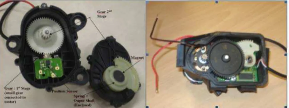
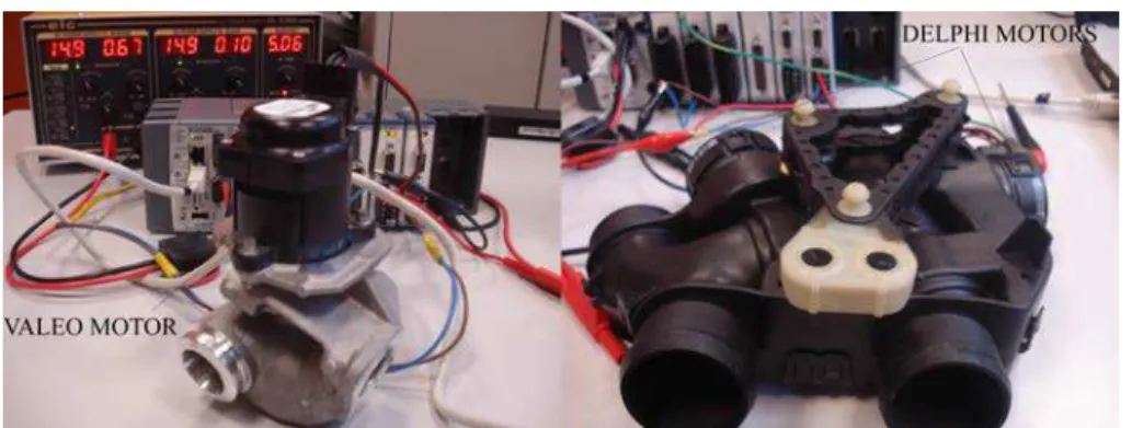
Figure 2.4. Torque Motor based actuators (a)Valeo EGR Actuator (b)DELPHI
Double Air Mixer . . . 39
Figure 2.5. Simplified working principle of torque motors . . . 40
Figure 2.6. Multi-coil torque motor . . . 41
Figure 2.7. Valeo torque motor . . . 42
Figure 2.8. Torque Motor Characteristics . . . 42
Figure 2.9. Expected characteristic of a Single Action Mechatronic Actuator . . 43
Figure 2.10.Experimentally obtained characteristics of two Single Action Mecha-tronic Actuators . . . 44
Figure 2.11.Deadband . . . 45
Figure 2.12.Hysteresis . . . 46
Figure 2.13.Dead Zone . . . 46
Figure 2.14.Block diagram of Motor-Spring system . . . 47
Figure 2.15.Actuator Characteristics w.r.t. Duty Cycle . . . 49
Figure 2.16.Friction: a: Static and Coulomb b: Static, Coulomb and Viscous c: With Stribeck Effect . . . 52
Figure 2.17.Stribeck Stick-Slip observed in Single Action PMDC Actuator . . . 54
Figure 2.18.Hunting Effect in Single Action PMDC Actuator . . . 55
Figure 2.19.Karnopp Model . . . 56
Figure 2.20.Experimentally obtained characteristics of two Single Action Mecha-tronic Actuators at different temperatures . . . 59
Figure 2.21.AMESim Model of Single Action Mechatronic Actuator . . . 60
Figure 2.22.AMESim Model of Double Action Mechatronic Actuator . . . 60
Figure 2.23.Actuator Test Bench . . . 61
Figure 2.24.Actuator Test Bench Block Diagram . . . 62
Figure 2.25.Static Validation . . . 64
Figure 2.26.Dynamic Validation . . . 65
Figure 2.27.Worn out actuator parts . . . 66
Figure 2.28.Torque deterioration with age . . . 67
Figure 3.1. DV6TED4 Test bench (Faurecia) . . . 70
Figure 3.2. Controller Structure . . . 71
Figure 3.3. Torque Maps . . . 73
LIST OF FIGURES xi
Figure 3.5. Fuel Injection Unit . . . 74
Figure 3.6. VGT Control Unit . . . 75
Figure 3.7. EGR Controller . . . 77
Figure 3.8. EGR coefficient and inhibition . . . 78
Figure 3.9. EGR Local-Loop Controller . . . 78
Figure 3.10.Intake Manifold Pressure at 1500RPM, 40Nm . . . 79
Figure 3.11.Intake Mass Flow (g/s) at 1500RPM, 40Nm . . . 79
Figure 3.12.Exhaust Manifold Pressure at 1500RPM, 40Nm . . . 80
Figure 3.13.Comparison at 1500RPM, 40Nm . . . 81
Figure 3.14.Comparison at transition 1500RPM-2000RPM, 40Nm-70Nm . . . 81
Figure 3.15.EGR Mass Flow at 1500RPM, 40Nm . . . 82
Figure 3.16.EGR Mass Flow at 1500RPM, 40Nm . . . 82
Figure 4.1. Actuator under PID control in Temperature Variations . . . 86
Figure 4.2. Convergence of the sliding variable under Twisting algorithm . . . . 92
Figure 4.3. Convergence of the sliding variable under Super Twisting algorithm 93 Figure 4.4. Differentiator Simulation . . . 95
Figure 4.5. Reference Trajectory . . . 100
Figure 4.6. Simulation Results . . . 101
Figure 4.7. Comparison: Desired and Actual Trajectories (Nominal Conditions) 104 Figure 4.8. Quasi Continuous Controller under Temperature Variation . . . 105
Figure 4.9. Super Twisting Controller under Temperature Variation . . . 106
Figure 4.10.Tracking a sinusoidal trajectory . . . 108
Figure 4.11.Position Convergence, low-speed (Simulation) . . . 120
Figure 4.12.Position Convergence, high-speed (Simulation) . . . 121
Figure 4.13.Velocity Observer low-speed (Simulation) . . . 121
Figure 4.14.Velocity Observer high-speed (Simulation) . . . 122
Figure 4.15.Current Observer low-speed (Simulation) . . . 122
Figure 4.16.Current Observer high-speed (Simulation) . . . 123
Figure 4.17.Friction State Observer low-speed (Simulation) . . . 123
Figure 4.18.Friction State Observer high-speed (Simulation) . . . 124
Figure 4.19.Parameter Adaptation low-speed (Simulation) . . . 124
Figure 4.20.Parameter Adaptation high-speed (Simulation) . . . 125
xii LIST OF FIGURES
Figure 4.22.Position Convergence, high-speed (Experimental) . . . 126
Figure 4.23.Observer Convergence (x1), low-speed (Experimental) . . . 126
Figure 4.24.Observer Convergence (x1), high-speed (Experimental) . . . 127
Figure 4.25.Observed Velocity and Current, low-speed (Experimental) . . . 127
Figure 4.26.Observed Velocity and Current, high-speed (Experimental) . . . 128
Figure 4.27.Observed Friction State, low-speed (Experimental) . . . 128
Figure 4.28.Observed Friction State, high-speed (Experimental) . . . 129
Figure 4.29.Worst case condition (600mN.m Load Torque) . . . 129
Figure 4.30.Temperature Variation . . . 130
Figure 4.31.Positioning Response (Exhaust Pressure: 2bar) . . . 131
Figure 4.32.Tracking Response (Exhaust Pressure: 2 bar) . . . 131
Figure 4.33.Positioning Response (Exhaust Pressure: 3bar) . . . 132
Figure 4.34.Tracking Response (Exhaust Pressure: 3 bar) . . . 132
Figure 5.1. VGT with vane actuation mechanism . . . 136
Figure 5.2. VGT Vanes, closed and open . . . 138
Figure 5.3. VGT mechanical diagram . . . 139
Figure 5.4. Velocity components of air-flow through a vane . . . 139
Figure 5.5. Exhaust gas flow through VGT . . . 142
Figure 5.6. Velocity triangle . . . 145
Figure 5.7. Blade geometry . . . 146
Figure 5.8. Gas outlet angles vs. cos−1(o/s) (straight back blades operating at low mach numbers) . . . 147
Figure 5.9. Finite element division of VGT vane . . . 147
Figure 5.10.Forces on the vane . . . 157
Figure 5.11.Physical positions of primary lever pivot point (A), crank rotation axis (C) actuator position (B) . . . 158
Figure 5.12.Turbocharger geometry with all dimensions . . . 160
Figure 5.13.A Simulator based on C compiler code to solve 1D flow equations . . 162
Figure 5.14.Output results of the QtCreator simulator . . . 163
Figure 5.15.Comparison of turbine inlet pressure, Engine: 2000RPM, 100Nm . . 164
Figure 5.16.Comparison of turbine inlet pressure, Engine: 2000RPM, 150Nm . . 164
Figure 5.17.Comparison of aerodynamic force on actuator, Engine: 2000RPM, 100Nm . . . 165
LIST OF FIGURES xiii
Figure 5.18.Comparison of aerodynamic force on actuator, Engine: 2000RPM,
150Nm . . . 165
Figure B.1. Electromagnetic coefficients of different actuators . . . 175
Figure B.2. Static friction values of different actuators . . . 175
Acknowledgement
There are a number of people without whom this thesis might not have been written and to whom I am greatly indebted. In the spirit of fairness, this work is dedicated to all of them:
To my parents, Nasreen Talat and Shakil Ahmed, who have been sources of encourage-ment and inspiration throughout my life in their own different ways and who taught me to question. Also to my more-like-parent brother and sisters (in-laws included), who have still not given up on the idea that they can make a disciplined person out of me. I should also mention my nieces and nephews, just for being there.
To my director M. El Bagdouri and my supervisor M. Laghrouche, for their valuable time, insightful advice and constructive criticism. They patiently (but mostly impatiently) pro-vided the vision and guidance necessary for completion of this dissertation. Among the list of mentors, I would also like to mention Mr. Rais ul Hassan, who has spent the better part of his life in proving to adolescents that maths is our friend.
To my friends, colleagues and teammates Imad Matraji, Mohammed Harmouche and Adeel Mehmood. Together we turned the bleakest moments of research into memorable ones and are looking forward for more. Specially, to Nafisa M. R. Zaman, who actively supported me in my determination and, at times, kept me determined when I wasn’t really so.
In the end, a special note of thanks to the industrial partners of project SIMBA, particulary David Guyon, Julien Peuch, Anita Grenier of SOGEFI SAS, Denis Ragot of Faurecia, Landry Saussol of LMS international and Guillaume Alix of IFP. Thank you for the time and effort expended in order to churn out a working simulator.
Introduction
The global competition in today’s automobile market is a major challenge faced by the automobile industry. It is also associated with environmental and social issues such as sustainable development and anti-pollution campaigns. For example, in Europe, all vehi-cles equipped with a diesel engine will be required to substantially reduce their emissions of nitrogen oxides as soon as the Euro VI standard enters into force (see Figure 0.1). For example, emissions from cars and other transport vehicles will be capped at an additional reduction of more than 50% compared to the current Euro V standard [1]. Combined emissions of particulate matter and nitrogen oxides (NOx) from diesel vehicles will also be reduced.
In order to meet these challenges and to offer products nearer to the clients’ requirements, the industry needs to double its effort in research, development and innovation. Invest-ments are required in high performance development tools that would reduce the time to market and the number of prototypes, and optimize their technical solutions. This also offers an opportunity for introducing new high performance products that are in con-junction with the social and environmental battle against air pollution caused by vehicle emissions. In order to avail this opportunity, the two key players of the automobile indus-try, namely the automobile manufacturers and Original Equipment Manufacturers (OEM or parts manufacturers), need to work in tandem. Their relationship is characterized by three major parameters:
• Structure: Both manufacturers are of different sizes and have different internal cultures, but they are confronted with similar competitive challenges.
2 INTRODUCTION
• Competition: OEMs need to search ways for escaping the restrictive frame of unified parts, and to identify problems yet undiscovered, permitting them to extend their margins of competence.
• Regulations: The increasingly strict regulations on pollution have made the work-ing modes more complex.
Figure 0.1. Evolution of European Emission standards
At present, automobile manufacturers develop the specification of individual parts sepa-rately for each OEM, while ignoring the mutual interaction between the parts. It is clear that this approach is not consistent with the actual challenges. Improvements in complex systems need to be introduced at the conception and design level with mutual interac-tions taken into account. For improving engine performance in terms of consumption and emission, a better understanding of the engine air-path is required, which demands in-depth knowledge related to the different physical phenomena related to it, as well as the interaction between its subsystems. Ambitious research is required around the internal combustion engine, concentrated towards the combustion process as well as the air-path dynamics. This is not possible without the mutualization of industrial competence, re-search and development skills manufacturers and experts. Fortunately, the OEMs are convinced that joint-research efforts in their domains related to engine air-path is the ab-solute need of the day. In this spirit, the project ”Simulation de la boucle d’air” (SIMBA)
0.1. DIESEL ENGINE AIR-PATH 3
was conceived with the collaboration of industrial and academic partners, with the objec-tives of
• obtaining precise dynamic models of different parts of the engine air-path
• in-depth research of the mutual interaction between these parts and subsystems, including their effect on the global performance of the air-path
• developing a ”predictive simulation tool” to improve product development in its conceptual phase, thereby reducing delays and techno-economical compromises This thesis follows two major axes of research in the context of SIMBA. The first axis is oriented towards the problems related to the modeling of the global air-path system. This includes interlinkage of the subsystems of the air-path into a complete system, as well as consolidation of the efforts of different partners of the project into the above mentioned simulation tool. The second axis of research is focused on the modeling and control of mechatronic actuators. These actuators are basically motorized control valves used for regulating the air-mass flow in different sections of the air-path. In this chapter, we will explore the air-path and its subsections, and identify the problems that are addressed in the rest of this report.
0.1
Diesel Engine Air-path
The diesel engine, developed by Rudolf Diesel (March 18, 1858−September 29, 1913), is a Compression Ignition (CI) internal combustion engine. In this engine, fuel is injected directly into the cylinder and ignited by the heat generated through the compression of the working fluid (air). The output torque is controlled by varying the quantity of injected fuel, thereby varying the air-fuel ratio. This principle contrasts with Spark-Ignition (SI) engines, in which an electric spark ignites a premixed air-fuel mixture of a fixed ratio. Diesel or CI engines generate ignition temperature by compressing air at much high com-pression ratios as compared to SI engines. The high cylinder temperature and pressure required for ignition in CI engines result in improved fuel efficiency, higher than any other internal or external combustion engine [2].
In diesel engines, air is compressed in the cylinder and fuel is injected at the exact mo-ment at which ignition is required. This is done to avoid self-ignition of the fuel at lower
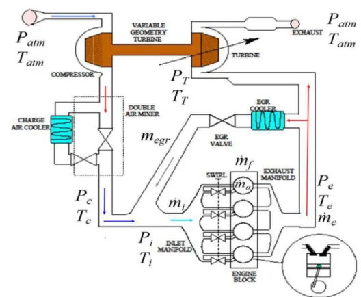
4 INTRODUCTION SWIRL 00 00 00 00 00 00 00 00 00 00 00 11 11 11 11 11 11 11 11 11 11 11 000 000 000 000 000 000 000 000 000 000 000 111 111 111 111 111 111 111 111 111 111 111 EGR COOLER GEOMETRY TURBINE EXHAUST COMPRESSOR VARIABLE TURBINE VALVE EGR MANIFOLD CHARGE AIR COOLER DOUBLE AIR MIXER INLET MANIFOLD EXHAUST ENGINE BLOCK
Figure 0.2. Engine air-path
pressures. The engine air-path maintains sufficient pressure in the intake manifold of the engine to ensure that the air mass-flow into the cylinder meets the combustion require-ment [3]. It indirectly controls the cylinder temperature as well, in order to reduce NOx formation. In this way the air-path is responsible for the management of the inlet and exhaust air quality and quantity for efficient combustion and pollution reduction [4, 5]. Let us now see how this management is achieved in modern diesel engine air-paths.
0.1.1 Pressure Boosting (Turbocharging)
The engine power or torque of a CI engine depends upon the the amount of fuel that can be burned efficiently inside it, i.e. the amount of air present in the cylinder. The power output can therefore be increased by forcing more air into the cylinder, achieving high Air to Fuel ratio (AFR) [6]. The air mass-flow is increased by increasing the pressure
0.1. DIESEL ENGINE AIR-PATH 5
in the intake manifold, which is why this process is called pressure boosting. This can also be interpreted as reduction in Brake Specific Fuel Consumption (BSFC), which is an immediate measure of increase in the engine’s efficiency [2].
Mechanically driven air compressors, connected directly to the engine crankshaft, were initially introduced for this purpose. These superchargers had the major advantage of quick response to speed changes [7]. However, the power to drive the compressor was a parasitic load on the engine output. They also had higher cost, greater weight, more chances of mechanical failure and higher noise levels. The drawbacks of superchargers were overcome by exhaust gas turbochargers. Turbochargers use a turbine to run the compressor. The turbine itself is run by the exhaust gas, utilizing energy that would otherwise have been wasted. The compressor, running through the turbine forces air into the intake manifold, providing the pressure boost. Turbochargers are now a common feature in diesel engine automobiles [3]. The advantages of turbocharged engines are [7, 8, 9]:
• Due to the lower volumetric displacement required, the power-to-weight ratio of the engine is higher than naturally aspirated engines.
• The fuel consumption of a turbo engine is lower, as some of the normally wasted exhaust energy contributes to the engine’s efficiency.
• The turbo engine’s installation space requirement is smaller due to its smaller size.
• The high-altitude performance of a turbocharged engine is significantly better due to better performance of the turbine at low atmospheric pressures.
0.1.2 Exhaust Gas Recirculation
As discussed before, diesel engines are more fuel-efficient due to high compression and lean burning. However, they cannot use the pollutant reduction systems that are successful in gasoline engines [9]. While the air-fuel ration inside the cylinder of diesel engines can be as high as ten times the stoichiometric ratio, the fuel mixture is heterogeneous because combustion starts as soon as the fuel injection begins. The prevailing flame temperature therefore, is high at localized points in the cylinder. This increases the specific rate of
6 INTRODUCTION
EGR was proposed to alter combustion in spark ignition engines for knock suppression [11, 12]. This proved to be one of the most effective method for reducingNOx emissions in diesel engines. In this method exhaust gas is added to the fresh air at the intake. The addition of inert gases to the intake mixture reduces peak burned gas temperatures and hence, reduces NOx formation rates while improving fuel consumption [5]. Recently, EGR has been declared as a necessary means to meet the United States Environmental Protection Agency (EPA) NOx regulations [11].
0.2
Air-path Subsystems
The functions of the air-path, mentioned in the previous section, require a certain number of subsystems to work together. As seen in Figure 0.2, the integral components of the engine air-path are the turbocharger, exhaust gas recirculation (EGR) valve [9, 4, 13] and some auxiliary systems such as heat exchanger, swirl system etc. Throttle valves are usually not required in CI engines, since engine speed can be controlled directly by controlling the fuel injection [14]. In this section, we will explore the major subsystems and their control mechanisms.
0.2.1 Variable Geometry Turbocharger (VGT)
As discussed above, the turbocharger turbine turns the compressor to provide pressure boost. In order to regulate the intake manifold pressure, the compressor and turbine speed needs to be controlled. In modern turbochargers, this is achieved by varying the geometry of the turbine inlet. A variable geometry turbocharger (see Figure 0.3) has moveable vanes located around the turbine. These vanes allows the turbine flow cross-section to be varied in accordance with the engine operating point.
0.2.1.1 VGT actuator
The position of the VGT vanes is controlled by a dedicated VGT actuator. The VGT actuator is a linear actuator, connected to the vanes through a rack and pinion crankshaft and a unison ring. The latter ensures that all the vanes move together. This actuator can be electro-mechanical or electro-pneumatic.
0.2. AIR-PATH SUBSYSTEMS 7
Figure 0.3. Mechanical diagram of a variable geometry turbocharger
0.2.2 EGR Valve
The flow of exhaust gas recirculated towards the intake manifold is regulated by a control valve between the intake and exhaust paths. This valve is a mechatronic actuator, which typically consists of a linear (globe) valve with a motor and a cam or screw drive to convert rotary motion to linear motion (Figure. 0.5).
0.2.3 Cooling Systems
Due to compression and combustion, gas temperature in different sections of the air-path can be very hot. Therefore, different means are employed for temperature regulation. One such method is the Double Air Mixer (Fig. 0.6), which maintains the temperature of the fresh air entering the intake manifold by mixing hot and cold air to maintain the air temperature. This mixer is actuated by two separate mechatronic butterfly valves.
0.2.4 Swirl actuators
Turbulent air mixes better with the fuel inside the cylinder. This mitigates some of the disadvantages of heterogeneous combustion (such as excessive NOx). In some diesel engines, a swirl actuator is integrated in the air inlet manifold, the geometry of which
8 INTRODUCTION
Figure 0.4. VGT with an electro-pneumatic actuator system
adds turbulence to the air flow (Figure 0.7). The flow of swirled air is controlled by a mechatronic actuator [15].
0.3
Problems and contributions
The discussion about the air-path and its subsystems brings forth some important points concerning its design and control. These are highlighted as follows:
• The coupling of the intake and exhaust paths, due to VGT and EGR, creates a sig-nificant interdependence between the subsystems. An air-path cannot provide the
0.3. PROBLEMS AND CONTRIBUTIONS 9
Figure 0.5. EGR actuator
Figure 0.6. Double air mixer
performance expected according to the design specifications, if this interdependence is not taken into account at the design level. In other words, the dynamics and limi-tations of the air-path subsystems need to be studied together, in order to determine the behavior of the complete air-path.
• The performance of the air-path subsystems is dependent upon the performance of their actuation systems. Therefore, the mass-flow characteristics of the subsystems are not sufficient in order to determine the global behavior of the air-path. In such complicated systems, where the effect of variation of one actuator affects the global system, it is important to model the system response during actuator transition [13],
10 INTRODUCTION
Figure 0.7. Inlet swirl actuator
and the characteristics and dynamics of the actuators also need to be taken into account.
In addition to these points, the discrete, cylinder-by-cylinder operation of the engine re-sults in pulsations in the intake and exhaust air-flow. Therefore, the dynamics of air mass-flow are non-stationary at the turbine and intake manifold, even when the motor is in stationary regime (stable). On the other hand, the manifold air pressure sensors used in the intake manifold, do not have sufficient bandwidth to measure the pressure changes due to these pulsations, and their effect is generally disregarded in commercial engines. Improvements in the air-path design and control methods require that these pulsating dy-namics and their influence on air-path subsystems be studied and robust control methods be developed to mitigate their negative effects.
These problems are at the core of the research work presented in this thesis. The goal is to develop a simulator that enables the industrial actors to study the these problems at design level, virtually realize scenarios that have not yet been considered practically, mark the areas of possible improvement in their system and control design and introduce new and better products (subsystems and complete systems) in the market. The overall work and contribution can be divided into three main segments, discussed below.
0.3. PROBLEMS AND CONTRIBUTIONS 11
0.3.1 System Modeling
This part addresses the global air-path modeling, taking into account the pressure and air mass-flow dynamics in and between different subsystems of the engine air-path. This includes the addition of a discrete combustion model with the air-path model, in order to simulate the above-mentioned pulsating flow and problems related with it. As part of the Project SIMBA, the research and validation were performed using the commercial DV6TED4 4-cylinder, turbocharged engine. However, the model can be parameterized to the specification of any other engine and air-path.
0.3.2 Actuator Modeling
The modeling of the actuator dynamics in the engine environment is not only important from the air-path design point of view, but also from the control aspect, since the air-path can only meet its design specifications if its subsystems and their actuators work accu-rately. In this regard, the effect of flow characteristics, temperature, parametric variations and external forces also needs to be taken into account. On the other hand, the model also needs to be suitable for control design and implementation purposes. Therefore, ac-tuator modeling has been given special attention in this thesis, taking into account their nonlinear dynamics and environmental influence.
One particular force worth mentioning here, is the aerodynamic force exerted on the VGT vanes by the exhaust gas flow. It is an important external force that has not received much attention in research, yet its influence on VGT control cannot be neglected. This force has also been studied and modeled in this work.
0.3.3 Actuator control
In practical application, the global air-path control task is facilitated by local-loop actu-ator controllers, which manage the actuactu-ator positioning tasks while the global controller generates positioning references in accordance with the engine’s operating point. The third segment of this thesis is dedicated to the development of advanced robust controllers for local control of actuators. Using the actuator models, different control methods are devel-oped, and then experimentally evaluated in terms of their response time and robustness to parametric variations, operating environment and external disturbances.
12 INTRODUCTION
0.4
Thesis Structure
This report is divided as follows:
Chapter 1 deals with modeling of the air-path and its subsystems. The importance of both, Discrete Event Modeling (DEM) and Mean Value Modeling (MVM) are high-lighted. Then, combustion modeling is discussed along with the intake and exhaust mass flows and EGR. The VGT is discussed in detail and modeling of mass-flow characteristics in the compressor and turbine are discussed. Power coupling between these stages is also modeled. In the end, simulation platforms are discussed and the implementation of the air-path simulator in AMESim is presented.
Chapter 2 is dedicated mechatronic actuator technologies that are commonly found in engine air-paths, and their modeling. The mechatronic actuation methods mostly found in commercial air-path valves are identified and a generic model is developed. This model takes into account the nonlinear characteristics of the actuators due to friction as well as the effects of temperature on their performance The parametric identification method for the model is described for its adaptation to different specific actuators. The model is experimentally validated using different commercial actuators. Integration of these models in the simulator is also discussed, and the actuators associated with the DV6TED4 engine are incorporated.
Chapter 3 contains the validation of the complete simulator. The results generated by the simulator are compared with the data obtained during experimental tests conducted during the project. As this required the simulator to be linked with the controller used in real tests, the open ECU controller was implemented in Matlab Simulink and an interface was developed between AMESim and Simulink. This controller is also described in this chapter. The results show that the simulator’s outputs match the physical quantities of the real system.
Chapter 4 presents the development and experimental validation of different controller for local control of actuators. This study has been carried out, keeping in mind the present requirements and limitations of the automobile industry. The first part consists of a com-parative study, in which various popular control methods were implemented on an air-path actuator. Their performance is compared in terms of response time and robustness against
0.4. THESIS STRUCTURE 13
parametric uncertainty (due to temperature changes) and load variation. In the next part, an advanced adaptive backstepping controller is developed, which dynamically adapts to variations in friction and external load. The performance of this controller is also demon-strated using simulation and experimental results.
Chapter 5 addresses an important problem in the air-path control, i.e. modeling of the aerodynamic force exerted on the VGT vanes by the exhaust gas flow. Modeling of this force is essential in the simulator as it affects the dynamics of the VGT actuator. In this chapter, a 1D exhaust gas flow model is obtained, which allows more accuracy in predicting the flow component acting on the VGT vanes. Using this model, the force exerted on the VGT vanes is estimated using finite element analysis of the vane geometry. The transfer of this force from the vane to the actuator is calculated, through geometric analysis of the linkage mechanism. Using these calculations, a simulation tool is developed which estimates the aerodynamic force using the turbine inlet states. The tool is experimentally validated using results obtained from engine test bench measurements.
Chapter 1
Airpath Modeling
1.1
Introduction to Engine and Air-path Modeling
The diesel engine is a complex physical machine, in which numerous chemical, thermal and mechanical processes occur at the same time. Therefore it is unrealistic to expect that a single simulator will match the specific requirements of each engine process [16]. For example, the mean engine torque is a nonlinear function of many variables, such as fuel quantity and injection timing, air-fuel ratio, speed, EGR etc, and accurate simulation using all these parameters is too time consuming for control purposes [9]. On the other hand, these processes are interdependent to such an extent that simplifying approaches may lead to completely inaccurate results. Therefore, research in a particular domain related to engines (e.g. fuel efficiency, pollution reduction..) still requires that processes with indirect influence be taken into consideration.
Certain processes in the engine are dependent upon time only. However, many other processes are discrete in nature and depend upon the engine’s crankshaft position. The combustion process itself is highly transient, with large and rapid temperature and pressure variations [3]. These discrete processes are very fast (a few milliseconds for a full engine cycle) and usually are not accessible for control purposes [9]. Moreover, their models are complex and are not useful for the application in real-time feedback control systems [17]. Therefore, their behavior is often approximated with mean value models. However, their discrete nature cannot be ignored in control design, as they may have serious repercussions
16 CHAPTER 1. AIRPATH MODELING
on the overall performance of the engine system.
In this section, we will first look into the two modeling methods (mean and discrete) and classify important engine processes accordingly. In the light of this discussion, we will establish the objectives and goals of engine air-path modeling for this chapter.
1.1.1 Mean Value Models
Mean Value models (MVM) neglect the discrete cycles of the engine and assume that all processes and effects are spread out over the engine cycle [9]. All subsystems of the engine are modeled as lumped volume parameters. The reciprocating behavior of the engine is approximated by introducing delays between cylinder-in and cylinder-out effects. For ex-ample, the torque produced by the engine does not respond immediately to an increase in the manifold pressure. Therefore, in an MVM, it is updated after the induction-to-power-stroke (IPS) delay [18].
The complexity of Mean Value Engine Models is suitable for design of control and super-vision systems [19].This modeling method is clearly insufficient for modeling the engine dynamics itself. However, other continuous time processes, which do not depend directly upon the crankshaft position, can be represented by MVMs satisfactorily. Examples of the continuous-time subsystems are the intake manifold dynamics, the acceleration of the crankshaft, the turbocharger speed dynamics. These models are commonly used in air-path control design, examples of which are [20, 21, 22, 23, 24]
1.1.2 Discrete Event Models
The term Discrete event models (DEM) is used as an abuse of terminology (as proposed in [9]), to refer to models that take into account the reciprocating behavior of the engine. This means that the independent variable in these models is not time, but the crankshaft angle. The discrete working principles of the subsystems must be considered in the following cases [9]:
• When the system representation and controller design are simpler in the crank-angle domain.
1.1. INTRODUCTION TO ENGINE AND AIR-PATH MODELING 17
• When the control system has to achieve bandwidths that may raise synchronization problems.
• When cylinder-individual effects have to be analyzed
DEM are often formulated under the assumption that the engine speed is constant. In this case, their structure is simplified as they become equivalent to sampled data systems, for which a theoretical background exists [9]. Subsystems that often are modeled as discrete-event systems are the torque production, the gas exchange of the individual cylinders, the injection and the ignition processes, etc. [25, 16, 22].
1.1.3 Chapter Objectives and Goals
A major issue in the improvement of Diesel engines lies in the architecture and the control of the air-path. Fuel efficiency and pollution control regulations are forcing manufacturers to develop complex air-paths. For example, two-stage turbochargers are used to reduce the fuel/air equivalence ratio and variable actuation allows the reduction of the response time to high EGR demand, etc. [16]. Virtual simulation support allows manufacturers the facility of fast development (reducing time-to-market), while reducing prototyping costs. On the other hand, application expectations have to be accurately defined in order to adapt simulation with coherent models [22]. This is the motivation behind this work, in which we focus upon physical modeling and simulation of the diesel engine air-path at component level. This would allow manufacturers to study the behavior of the engine system virtually, with respect to changes in one or more components.
In this case, an air-path model cannot be attained without integrating a sufficiently ac-curate combustion model as well. The combustion model needs to reflect the effect of reciprocation on the mass-flow; therefore MVMs are not a choice. The physical nature of gaseous mass-flow itself is continuous in time. Therefore, if the engine model generates the discrete pressure and flow conditions on the crankshaft level, then the pulsating flow in the air-path can be accurately modeled using MVMs for air-path components.
In this chapter, we will study and model the physical dynamics of each part of the air-path, shown in Figure 1.1. Then, the models are implemented in a simulator, using AMESim platform. This software is one of the leading tools in the automotive industry for automo-tive and aerospace simulations. It was chosen for this study as it has abundant libraries for
18 CHAPTER 1. AIRPATH MODELING
Figure 1.1. Air-path variables and airflow. Variables: p =pressure, T =temperature, m =˙ mass flow. Subscripts: i =intake manifold, e =exhaust manifold, T =Turbine, c =compressor, f=fuel,
α =cylinder, at m =atmosphere,eg r =EGR
facilitating air-path design. In this chapter, the focus is on the air-flow dynamics and as an initial step, the scope is simulation is 0D, i.e. the lengths of transmission lines are not taken into account. The simulator will be further improved in the subsequent chapters, by adding actuator dynamics as well. The extension to 1D simulations will be considered in the future.
NB: In the rest of the paper, the notations and subscripts of Figure 1.1 will be used as reference.
1.2
Engine Combustion
Due to its reciprocating action, an internal combustion engine naturally discrete-event system. Engine models are primarily developed to study the combustion properties and torque generation. We are not interested in any of these processes directly; our focus
1.2. ENGINE COMBUSTION 19
is to model the effects of reciprocation on the air-path. In this regard, the evolution of combustion is an important factor in the choice of model, as it defines the pressure dynamics inside the cylinder, which in turn, are the cause of pulsations in the air-path. Let us first briefly review some existing models based on this property.
1.2.1 State of the art
The shaft work by a diesel engine is the sum of work on the piston by the pressure produced by the heat released by combustion and the losses due to pumping, heat transfer and friction. The variety of combustion chambers and types of fuel injection equipments influence the heat release rate characteristically [9].
1.2.1.1 Zero-dimensional model
These models are attractive because they describe heat release rate by simple algebraic equations [26]. An important example of such a model is presented in[27], in which a strong relationship between fuel injection and heat release rates. However, this method is not accurate as there are no universal decay constants for elemental heat-release rates in different types of engines and their operating conditions.
1.2.1.2 Models based on fluid dynamics
These models are multidimensional models due to their inherent ability to provide detailed geometric information on the flow field based on the solution of the governing equations [26]. Several three-dimensional simulation models of injection, mixing and burning in diesel engines exist [28, 29], which describe the inner mechanism of diesel sprays and their influence on heat release. However, the volume of computation in multi-dimensional models is restrictive in carrying out detailed studies. In addition, their sub-models require a thorough validation with detailed experiments before employing them confidently in engine design work.
1.2.1.3 Phenomenological models
In phenomenological models, details of different phenomenon happening during combus-tion are added to basic equacombus-tion of energy conservacombus-tion [26]. In the simplest approach, [30] assumed the growth and motion of the spray within the chamber and [31] found that
20 CHAPTER 1. AIRPATH MODELING
the spray structure offered the clue to better heat release predictions.
The description of the thermodynamic conditions in the combustion chamber is based on a mathematical formulation of the conventional two-zone approach. It is assumed that at any time during the combustion process, the cylinder volume is divided into two zones, corresponding to burned and unburned gas regions [32]. In each zone the thermodynamic state is defined by the means of thermodynamic properties and the specific heat of each gas component changes according to the approximated formula from the JANAF thermo-dynamic properties table [33]. The quasi-dimensional thermothermo-dynamic model incorporates several sub-models to take into account several physical phenomena (turbulence, vapor-ization, spray and entrained gas mass flow rate). So far, this model provides the most accurate heat release approximations, while keeping low on computational requirements.
1.2.2 Lebas’ Phenomenological Model
This phenomenological combustion and pollutant emissions model [34] is a recent develop-ment on Barba’s approach [33]. In this model, the combustion process is divided in three parts:
• A cool flame, if Low Temperature Combustion conditions are met
• Pre-mixed burning with the hypothesis of flame propagation in the pre-mixed zone
• Oxidization the remaining fuel in a mixing controlled combustion mode.
The pressure evolution inside the combustion chamber is computed using the following equation: d p d t = ρ µ d r d tT + d T d tr ¶ +dρ d tr T, (1.1)
whereρis the density of the gas mixture inside the cylinder r is the perfect gas constant. For a mixture of N gases, r is determined byr =
N
X
i =1
xiri, where xi are the mass fractions of individual gases and ri are their gas constants. T is the temperature, the evolution of which is determined by Barba’s heat release model [33]. This model was chosen to be integrated in the simulator due to its accuracy and ease of implementation, as rich support for this model has been provided by IFP (France), in AMESim.
1.3. ENGINE INTAKE 21
1.3
Engine Intake
From the air-path point of view, the engine works as a volumetric pump [9], i.e. the intake mass-flow is approximately proportional to its speed. Therefore, for a four stroke engine it can be modeled as
˙
mi= ρiV = ρ˙ iηv
Vdωe
4π , (1.2)
whereρi is the density of the gas at intake (dependent upon the intake manifold pressure and EGR ratio), ηv is the volumetric efficiency of the engine and Vd is the displaced volume.
1.4
Engine Exhaust
Since line losses are not taken into consideration, it is assumed that the exhaust conditions are the same throughout the path and pressure is undiminished from the engine up till the VGT turbine stage (Pe = PT). The mass-flow is governed by the VGT position and the EGR.
1.5
Exhaust Gas Recirculation
Exhaust gas recirculation (EGR) redirects a portion of the cylinder exhaust gases into the intake manifold. As shown in Figure 1.1, the exhaust gas may be mixed directly with the intake flow or it may be cooled before mixing. As per the design of the DV6TED4 air-path, direct EGR is realized. The EGR mass-flow is regulated by a globe valve, conveniently referred to as the EGR valve. The flow dynamics are governed by the equations of orifice flow for compressible fluids, for an isothermal orifice with variable cross-sectional area.
˙ meg r = cdA(x) pe p RTe Ψ µ pe pi ¶ , Ψ µ pe pi ¶ = v u u tγ· 2 γ + 1 ¸γ+1 γ−1 f or pi< pcr ·p e pi ¸1/γ v u u t 2γ γ + 1 " 1 − µp e pi ¶(γ−1)/γ# f or pi> pcr (1.3)
where cd is the discharge coefficient of the valve, γ is the specific heat ratio, and R is the gas constant. The term pcr=
· 2
γ + 1
¸ γ γ−1
pe is the critical pressure, at which the flow reaches sonic conditions and velocity is choked [9]. The cross-sectional area function A(x),
22 CHAPTER 1. AIRPATH MODELING
depends upon the valve opening position x. For the purpose of this study, this function was determined experimentally for the EGR Valve used in the DV6TED4 engine, using the gas-flow test bench at SOGEFI Motor Systems. As the globe wall maintains the same orifice shape throughout its opening range, its discharge coefficient is assumed to be con-stant for all openings. It was estimated at 0.85, according to the geometry and channel specifications given in [35] and [36]. The valve was positioned at different opening per-centages, determined by the percentage input voltage with respect to the voltage required for full opening. The actuator was mounted on the test bench and different mass flows were forced through it at different openings. The resulting pressure difference across the valve was recorded. The results are shown in Figure 1.2.
It can be noted that as the objective of these experiments was to calculate the
ef-Figure 1.2. Mass flow and pressure difference of EGR Valve at different openings
fective area of the valve, these measurements were limited to mass flows, linear w.r.t. pressure differences. Based on these measurements, the area was calculated for each open-ing percentage, usopen-ing Equation (1.3). The resultant area function was obtained through interpolation:
A(x) = 0.0010251x5− 0.0031412x4+ 0.00349001x3− 0.0016442x2+ 0.0004x − (6.3816 × 10⁻²⁰),
1.6. VARIABLE GEOMETRY TURBOCHARGER 23
where the unit of A(x)ism2and x varies from0(valve closed) to 1(valve fully open). At
x = 1, the full area is 1.6195e − 004m2 or161.95mm2.
1.6
Variable Geometry Turbocharger
The turbocharger, as introduced in the previous chapter, uses the energy of the exhaust gas passing through its turbine, to run the compressor and provide pressure boost in the intake manifold. The variable exhaust inlet of a VGT (Figure 1.3) allows the turbine flow cross-section to be varied in accordance with the engine operating point [37]. When the VGT vanes are closed, the exhaust gases speed up (since they are passing through a smaller orifice) and the turbine spins faster. When they open, the gases slows down but there is a larger amount of gasses to spin through turbine and give it more pumping power. Thus it effectively adapts the intake pressure to match the engine’s needs during partial loads and transient running [38, 39]. As a result, the efficiency of the turbocharger and the engine is higher. Both intake and exhaust pressures are dependent upon VGT, the intake being regulated by the compressor and the exhaust by VGT vanes.
Figure 1.3. Mechanical diagram of a variable geometry turbocharger
1.6.1 Turbocharger mass-flow maps and correction
Manufacturers specify the performance characteristics of turbochargers in terms of the mass flow rate and isentropic efficiency for varying compressor speeds and pressure ratios
24 CHAPTER 1. AIRPATH MODELING
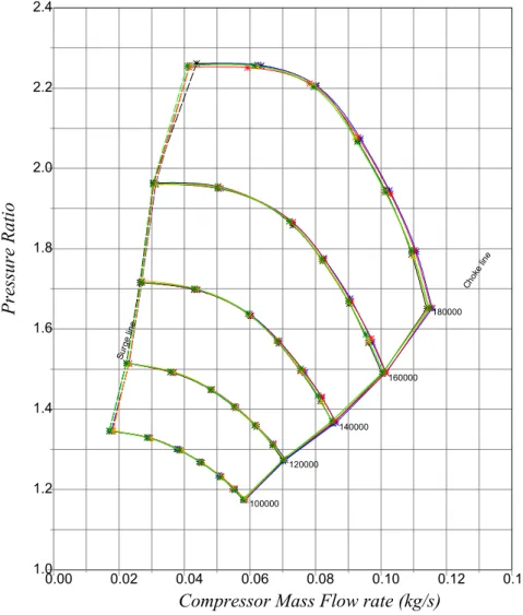
[40]. The flow performance curves of VGT used in the DV6TED4 engine are shown in Figures 1.4 and 1.5. The multiple data sets shown in Figure 1.5 correspond to flow characteristics at different VGT vane angles.
Figure 1.4. Compressor performance curves for VGT installed on DV6TED4
Conventionally, the performance maps are provided in terms of corrected mass flow rate
˙
mcor r and compressor rotational speedωcor r, which eliminate the dependence of the maps on inlet conditions. These corrections make comparison possible between different com-pressors with different speed and mass flow characteristics. The corrected parameters are
1.6. VARIABLE GEOMETRY TURBOCHARGER 25
Figure 1.5. Turbine performance curves for VGT installed on DV6TED4
scaled according to standard temperature and pressure (STP) conditions, corresponding to288.15K (15oC) and101.325kPa (1.01325 bar) in Europe. For specific inlet conditions, the actual speed and mass-flow can be calculated by
˙ m = m˙cor r δ p θ, ω = ωcor r p θ, (1.5) where θ = Ti nl et 288.15, δ = Pi nl et 101.325. 1.6.2 Compressor Power
Typically, the compressor stage of a turbocharger is of centrifugal type. The impeller rotation increases the velocity of the air, which is then decelerated in a diffuser. According to Bernoulli’s principle, this results in increase in the static pressure. According to [41], the power Pc, required to drive the compressor to obtain a specific mass flow rate m˙c is determined through the first law of thermodynamics:
Pc= ˙mc(hi− hat m) = ˙mccp(Ti− Tat m) , (1.6) where hx represent enthalpy and cp is the specific heat coefficient of the air at constant pressure. For a general isentropic process, the pressure ratio is related to the temperature
26 CHAPTER 1. AIRPATH MODELING ratio: T1,i s T2 = µp 1 p2 ¶γ−1 γ ,
where γ is the ratio of the specific heat of the working fluid at constant pressure and constant volume (cp/cv) and the subscript i s indicates isentropic process. In the case of compressor however, the process is not isentropic and the term isentropic efficiency ηc,i s needs to be defined, as
ηc,i s=
Ti ,i s− Tat m
Ti− Tat m
(1.7) where 0 ≤ ηc,i s≤ 1. Practically, Ti ,i s represents the theoretical temperature rise (as pre-dicted by the ideal gas law) andTi is the actual temperature rise. From here, the temper-ature ratio for a turbocharger compressor can be related to the pressure ratio as
Ti Tat m = 1 + 1 ηc,i s "µ p i pat m ¶γ−1 γ − 1 # ,
and Equation (1.6) becomes
Pc= ˙mccpTat m 1 ηc,i s "µ p i pat m ¶γ−1 γ − 1 # . (1.8) 1.6.3 Turbine Power
The modeling of turbine is similar to that of the compressor, as given by Equations (1.6), (1.7) and (1.8). The powerPT input depends upon the exhaust gas flowm˙T [41], calculated through the first law of thermodynamics:
PT= ˙mTcpTTηT,i s "µ 1 − pT pat m ¶γ−1 γ # . (1.9)
whereηT,i s is the isentropic efficiency of the turbine.
1.6.4 Turbocharger Speed
Using the relationship between the net power and net torque(P = τω), the rotational speed of the turbocharger is calculated as follows:
˙
ωt c =
PT− Pc
Jt cωt c
, (1.10)
1.7. SIMULATOR IMPLEMENTATION IN AMESIM 27
1.7
Simulator Implementation in AMESim
AMESim stands for Advanced Modeling Environment for performing Simulations of engineering systems. It is a multi-domain software that allows interconnection between systems of different physical natures (hydraulic, pneumatic, mechanic, electrical, thermal, etc.). Modeling in AMESim is based on Bond graph theory, i.e. systems are modeled using a set of dynamic equations and power is transmitted between systems by a combination of generalized effort and flow notions [42]. However, AMESim uses graphic icons instead of traditional graphs, based on the standard symbols used in the engineering field or symbols which give an easily recognizable pictorial representation of the system. Interconnections are made through ports defined on the icons and causality is ensured by fixed input and output ports of each icon. AMESim comes with a large number of containing models for different physical domains. These libraries are written in C language
As mentioned in the introduction, this software was chosen because its libraries are adapted for automotive applications. The air-path was developed in the general form as shown in Figure 1.1. The implemented scheme is shown in Figure 1.6. The parameterization to the specifications of the engine and air-path of the DV6TED4 engine system was made possible by the collaborative effort of the partners of Project SIMBA. The details of the components of this model are presented in this section.
1.7.1 Cylinder and Combustion
The cylinder model in IFP library represents a combustion model in a thermal-pneumatic chamber with a variable volume, pressure dynamics and wall heat exchanges (Figure 1.7). This is a discrete event model, designed for direct injection diesel engines. The working fluid is a mixture of three gases: air, fuel and burned gas. The fuel CxHyOz is defined by 3 parameters: x, y, z and the heating value (Net Calorific Value). Combustion is simulated by Lebas’ model [34, 43], which determines the heat release rate, and therefore the temperature evolution.
The additional important parameters required to configure this model are the cylinder geometry (bore, stroke, compression ratio), volume Vd, volumetric efficiency ηv, intake and exhaust valve characteristics, firing angle and number of injections. The pistons are connected to the crankshaft, upon which, the load torque is imposed through a rotary torque module (lower left of Figure 1.6).
28 CHAPTER 1. AIRPATH MODELING
1.7. SIMULATOR IMPLEMENTATION IN AMESIM 29
Figure 1.7. Cylinder Model
1.7.2 Intake and Exhaust Manifolds
As the air-path is modeled in 0D, the manifolds are modeled as constant volume chambers. The submodel provided in AMESim for this purpose can be configured to accommodate multiple gases, each with an associated mass flow rate and enthalpy flow rate. The model outputs are pressure and temperature, the latter being obtained using the ideal gas law. It can be seen in Figure 1.6 that the intake manifold is configured to receive fresh air from the turbocharger and burned gas from EGR. Air swirl is not taken into consideration, since the air-flow geometry is not studied in 0D models.
1.7.3 Exhaust Gas Recirculation
The EGR is implemented using a valve model based on equations of orifice flow with variable cross-sectional area (Figure 1.8), same as (1.3). A constant volume chamber is used to simulate the delay due to gas transmission lines.
1.7.4 Variable Geometry Turbine
The Variable Geometry Turbine (Figure 1.9) is modeled using three components: the turbine with variable flow area, the centrifugal compressor and an inertial component
30 CHAPTER 1. AIRPATH MODELING
Figure 1.8. EGR Model
representing the connecting shaft.
Figure 1.9. VGT Model
1.7.4.1 Turbine
The VGT vanes are defined in terms of percentage opening. The mass flow through the turbine is then determined using the manufacturer’s characteristic curves. The flow characteristics of the turbine are provided to the model in form of table that contains the numeric values of the curve data points. Hence, for each tested vane opening, the number of iso lines are defined in the table. Then, for each iso line, the number of data points and their values (pressure ratio and mass flow) are defined, as follows
1.7. SIMULATOR IMPLEMENTATION IN AMESIM 31
Vane POS0 Nb iso
RPM0 Nb Pr
PR0 mass0
PR1 mass1
... Vane POS1 Nb iso
RPM0 Nb Pr
PR0 mass0
PR1 mass1
...
The turbine power is calculated in the same way as mentioned in Section 1.6, using Equa-tion (1.9).
1.7.4.2 Compressor
The compressor receives input power from the turbine, and is modeled using the mass flow characteristics provided by the manufacturer. These characteristics are coded in the same manner as those of turbine, with the exception that vane position data sets are not present. The compressor dynamics are stabilized in the AMESim model by using smooth dissipation functions in cases where the rotational speed is very low. Power consumed by the compressor is calculated as mentioned in Section 1.6, using Equation (1.8).
1.7.4.3 Inertial shaft
This element adds the shaft inertia to the system. It is modeled simply as a mass rotating under an applied torque. The net speed of the turbocharger is calculated from the dynamic equation (1.10), using the turbine and compressor powers and the the moment of inertia of the shaft.
1.7.5 Fuel Injection
The fuel injection unit (Figure 1.10) is configured to provide a pilot injection and a main injection. The injection timing is configured in terms of crank angle position. Rail pressure and duration of injection are provided separately. More details of this unit are discussed in Chapter 3.
32 CHAPTER 1. AIRPATH MODELING
Figure 1.10. Fuel Injector Model
1.7.6 Auxiliary components
In addition to these major components, some minor additions were made in accordance with the specifications of DV6TED4. In the intake path, a pressure loss was introduced to simulate the effect of air filter and a heat exchanger was added between the compressor and the intake manifold. In order to validate the model, it was necessary to interface it with a controller already in use. Therefore, an interface block was also introduced to connect it to Simulink. The details of this interface and the controller are presented in Chapter 4.
1.8
Summary
In this chapter, the flow dynamics of the gases in the air-path were studied. The com-ponents were modeled and implemented to form a complete air-path simulator. In order to generate realistic pulsating flow and pressure, a cylinder by cylinder combustion model was used, in which injection and combustion are synchronized to the crankshaft angle.
The development in this chapter was focused on the gas flow inside the air-path. The flow dynamics depend on two important parameters; the position of the VGT vanes that governs the flow area through the turbine, and the position of the EGR valve that governs the flow area for EGR. In practice, these two are controlled using mechatronic actuators. The dynamics of these actuators play an important role in the overall performance of the air-path, as they have nonlinear characteristics. In the next chapter, a study is carried out on modeling of mechatronic actuator and their integration to complete the Simulator.
As a first step, the lengths of transmission lines were not considered in the model, keeping its level to 0D. In future, we intend to extend the models to obtain 1D simulations.