Methods in Creating, Transferring, & Measuring Cryogenic Samples for APT
S.S.A. Gerstl, R. Wepf
Scientific Center of Optical and Electron Microscopy (ScopeM), ETH Zurich, Zurich, Switzerland In its infancy, atom probe microscopy began as an analytical instrument primarily for metals and later semiconductors. As laser pulsing technology rapidly improved and computational capabilities were integrated, expediting many functions, analysis of additional materials classes were enabled, such as oxides, ceramics, and minerals [1]. All of these materials have something in common when prepared for APT analysis: they are dry, dense, and shaped into a specimen geometry with a sharp needle point with the region of interest (ROI) in the top 100s of nm of the apex.
In this paper, we discuss the potential and various fields of application where cryogenic-preparation and cryogenic-transfer of specimens into an atom probe is favorable compared to conventional room temperature methods that are standardized. Cryo-fixation of specimens involves methods long developed for cryo–electron microscopy capabilities [2]. The methods enable freezing in and arresting dynamic events of various types of states of highly energetic materials. Such freezing events can controllably take place in µsec to msec. This is more commonly known as rapid quenching (such as splat quenching) in metals, where relatively little attention is required after the solidified state is achieved. Thermal and atomic transport within the metals with respect to the cooling surface is of greatest concern, hence the resulting sizes of such materials are designed to be very thin (on order of several microns).
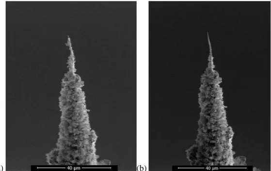
Specimens containing water however need special attention, particularly after the solidified state has been achieved. Care must be taken to avoid ice crystal formation, as observed on the shank of a typical APT specimen in fig. 1, which can damage the ROI structure or impair the electrical conductivity of the ideally vitreous frozen sample.
Developments from the life-science fields linking rapid freezing (Plunge and High Pressure Freezing) and vacuum-cryo-transfer with cryo–FIB/SEM processing have been adapted to our LEAP system, such that a frozen specimen in the FIB, fig. 1(a) can be transferred, with little contamination, to the LEAP, analyzed, and returned for imaging, fig. 1(b). The extensively tested hardware additions enable cryo-transfer of highly dynamic metals, environmentally sensitive or corrosive materials, and originally fluid based ROIs.
The various benefits of cryo-enabled LEAP for materials sciences will initially be addressed, whereby dynamically changing alloys, such as those suffering from natural aging or preferential/rapid corrosion, can be analyzed in their native, ‘frozen-in’ or unaltered states not having been exposed to thermal or environmental stimuli. Several pathways will then be discussed and shown regarding plunge freezing nanoparticles in liquid films on prefabricated tips, or in plasma FIB-fabricated vessels (fig. 2), or high pressure frozen bio-organic matter with the preparation of tips via ultramicrotomy and cryo-FIB milling.
Paper No. 0259 517
doi:10.1017/S1431927615003384 © Microscopy Society of America 2015
Microsc. Microanal. 21 (Suppl 3), 2015
https://doi.org/10.1017/S1431927615003384
References:
[1] D.Larson, et al, Local Electrode Atom Probe Tomography, (Springer, New York), 2013 p.201. [2] P.Echlin Low-Temperature Microscopy and Analysis (Plenum Press, New York) 1992.
[3] the authors would like to acknowledge the ongoing hi-level support from the EMEZ/ScopeM team.
(a) (b)
Figure 1. (a) A W needle plunge frozen and imaged via cryo-SEM showing ice crystal contamination prior to cryo-FIB final preparation. (b) The same needle having been transferred to the LEAP, analyzed, and returned to the cryo-FIB. Note changes near the apex where the field was applied and little to no change in contamination of the shank during transfers between instruments.
Figure 2. One example ‘microcup’, geometrically designed by plasma FIB capabilities for cryogenic
preparations of fluid based ROIs.
518 Microsc. Microanal. 21 (Suppl 3), 2015
https://doi.org/10.1017/S1431927615003384