An Advanced, Integrated Display System for Small,
High Speed Marine Craft
by
Christopher M. King
Submitted to the Department of Electrical Engineering and Computer Science
in Partial Fulfillment of the Requirements for the Degrees of
Bachelor of Science in Computer Science and Engineering
and Master of Engineering in Electrical Engineering and Computer Science
at the Massachusetts Institute of Technology
May 23, 1997 © 1997 Christopher M. King Author Approv Certif Accept
Department of Electrical Engin erng and Computer Sci ce --Jy 23, 1997a *ed by
T. Tuohy
Tec Supervisor
The Charles Stark Draper Laboratory
ied by
-Professo-i-n Leonard
ed by _ _ _ _ _ - ra__
Arthur ith
An Advanced, Integrated Display System for Small, High Speed Marine Craft
by
Christopher M. King
Submitted to the
Department of Electrical Engineering and Computer Science
May 23, 1997
in Partial Fulfillment of the Requirements for the Degrees of Bachelor of Science in Computer Science and Engineering
and Master of Engineering in Electrical Engineering and Computer Science
ABSTRACT
An integrated display system for a small, high-speed marine craft has been developed for monitoring and control of all boat systems, including navigation, internal and external sensors, and communications from multiple displays. The system integrates disparate data sources in a dynamic physical environment necessitating novel solutions for user interaction and information display technology. These solutions address particular problems in information display, instrumentation, human factors and visual perception within the constraints of commercial off the shelf (COTS) hardware and software development environments. Issues of extensibility in regards to new boat systems as well as improved user input methods and devices are also resolved.
Thesis Supervisor: John Leonard
Title: Professor, MIT Department of Ocean Engineering Technical Supervisor: Seamus T. Tuohy, Ph.D.
Acknowledgments
This thesis was prepared at The Charles Stark Draper Laboratory under Contract DAAD05-96-C-0049, W. Wyman, Draper Program Manager.
Publication of this thesis does not constitute approval by Draper or the sponsoring agency of the findings or conclusions contained herein. It is published for the exchange and stimulation of ideas.
Permission is hereby granted by the author to the Massachusetts Institute of Technology to reproduce any or all of this thesis.
(auth-•'s signature)
I would like to thank Seamus Tuohy for his tremendous support and encouragement throughout the entire project. It's been fun and I've learned a lot that I will carry with me. I couldn't have asked for a better project advisor.
Thanks also to my thesis advisor, John Leonard, whose advice helped me turn all of this into a real thesis. Thanks, especially, for accepting me on a moment's notice.
To Kevin Toomey, Daryl Dietz, and Bill Wyman, it was a pleasure working with you. Thank you for the trust and respect that you gave me as well as the advice and the knowledge.
Thanks to Mario Santarelli for taking me in last summer and providing me the stepping stone to this project and to Bill McKinney, who advised me on that project and always found time to give me a hand.
To Linda Leonard, thank you for all of your help starting well before this project. You've always been there whenever I needed anything. And to John Turkovich, who got
everything started for me at Draper three years ago.
Finally, to my parents, who have made all of my dreams possible, I could spend my whole life and not say thank you enough.
Contents
Acknowledgm ents... ... 3
Chapter 1 - Introduction... ... 6...
Chapter 2 - Statem ent of Problem ... ... 8
Chapter 3 - Project Overview ... 11
3.1 Requirem ents ... ... 11
3.2 Hardware Design... ... 12
3.2.1 Client/Server M odel ... 12
3.2.2 Input Interface ... 15
3.3 GUI M odels ... ... 16
Chapter 4 - GUI Development -Programmer's Model ... ... 19
4.1 Requirem ents ... ... 19
4.2 The Client M anager ... ... 21
4.2.1 Overview ... 21
4.2.2 Input Devices ... ... 24
4.3 The GUI Clients ... ... 25
4.3.1 Base IBS Dialog Class -IBSClientDlg... ... 26
4.3.2 Display Class ... ... 27
4.3.3 Instrum entation ... ... 28
4.3.4 The Display W izard ... 33
Chapter 5 - GUI Development -Designer's Model ... 37
5.1 Requirem ents ... ... 37
5.2 Im plem ented Clients ... ... 38
5.2.1 COM M S Client... ... 40
5.2.2 HELM Client ... ... 43
5.2.3 SYSTEM Client ... ... 44
5.2.4 ALARM S Client ... ... 46
6.1 H TM L Sim ulation... ... 65
6.2 Pow erPoint Sim ulation ... ... 66
6.3 Prototype System and Preliminary Design Review ... 67
6.4 Development System and Continuing Design Review... 68
Chapter 7 - Summary and Conclusions ... 69
Chapter 8 - Improvements and Extensions ... ... 71
R eferences... ... 73
Appendix A -GUI Client Extensibility ... 76
Chapter 1 - Introduction
The Integrated Bridge System (IBS) has been developed for the U.S. Navy Office of
Special Technology at the Charles Stark Draper Laboratory (CSDL) in conjunction with
several other companies. Specifically, CSDL had sole responsibility for the design and
development of the Graphical User Interface (GUI). In order to ensure rapid prototyping,
commercial off the shelf (COTS) hardware and software was used whenever possible.
The objective of this thesis is the design and implementation of a GUI for IBS which
addresses the issues of user interaction, display of diverse information, human factors,
and visual perception. In particular, the complications involved in producing such a GUI
for use in high-speed marine vehicles are examined. Additionally, issues of extensibility
in regards to future systems as well as improved user input methods and devices will be
resolved.
Chapter 2 describes the problems that exist with current instrumentation and
control systems on several Navy SEAL vessel and outlines the goals of the IBS project.
Chapter 3 provides an overview of the client/server architecture for the IBS system and
establishes the scope of the GUI within the overall project. Chapter 4 explains the GUI
from a programmer's perspective providing an understanding of the underlying
framework. This chapter in conjunction with Appendix A provides the information
necessary to make extensions, modifications, and additions to the GUI. Chapter 5 describes the GUI from the designer's perspective, explaining the display screens and
functions that were developed using the framework described in Chapter 4. Chapter 6
covers the evaluation and testing procedures that were followed throughout the project
and Chapter 7 draws conclusions from the development process. Chapter 8 explores
Chapter 2
-
Statement of Problem
The U.S. Navy currently has several maritime vehicles commonly used by Special
Operations Forces, the U.S. Navy SEALs, including (but not limited to) the MK V
Special Operations Craft (MK V SOC), the High Speed Assault Craft (HSAC), and in
development, the Very Slender Vehicle (VSV). These vehicles are used for missions
involving insertion and extraction, Coastal Patrol and Interdiction, and Target
Interception [1]. MK V SOC and HSAC, craft that are currently in service, are traditional
planing hull vehicles [25,26] while the VSV, currently under development, will be a
wave-piercing craft [24]. All of the vehicles can reach speeds exceeding 50 knots and can operate in high sea states resulting in a high shock environment on board [25,26],
although the wave-piercing ability of the VSV is an attempt to ameliorate this problem
[24].
Operation of these vessels involves a multitude of interfaces, functions, and
equipment that must be continually monitored or controlled from a console. While each
crew member has primary responsibilities relating to the displays located near them, they
also have additional secondary function responsibilities under certain conditions. Since
all of the boat systems have separate interfaces made up primarily of electro-mechanical
(E-M) instruments, space limitations on the bridge made it impossible to provide all of
the these displays for every crew member station [1]. Control of some onboard
setup. A display system was needed to replace the current bridge instrumentation on
these vessels and provide monitoring and control capabilities to all crew member stations.
Limitations of E-M displays and instrumentation were first addressed in both
military and civilian aircraft cockpits. In addition to occupying precious space within the
cockpit, E-M displays are difficult and expensive to maintain [13]. Beginning over
fifteen years ago, there has been a decided trend towards electro-optical (E-O)
multi-function displays (MFDs), often referred to as a glass cockpit, with virtually all new
aircraft incorporating this type of technology [15]. The Boeing 777, for example, was
designed to incorporate E-O MFDs [14]. Studies have shown that this type of display
technology has the potential of providing a substantial increase in the pilot's efficiency
[13].
Refitting a vehicle with such technology, as was required for the SEAL vessels,
has been a successful practice with various aircraft. Military craft such as the F-16 A/B,
F-16 C/D [18], F/A-18 E/F Hornet [17], and the F-22 [16] all have been retrofitted with
such displays. In fact, the F-22 is the first military aircraft to integrate an exclusively
glass cockpit [16].
This cockpit display technology has also been extended to other, non-aircraft
vehicles. Studies have been made to incorporate E-O MFDs into future ground combat
vehicles including the Bradley Infantry Fighting Vehicle and the Abrams Main Battle
Tank [23]. In fact, several MFDs proposed for the Abrams Tank utilize a bezel-mounted
twenty button interface, very similar to the button interface - described in the next chapter - chosen for the SEAL vessels.
Based on the success of integrated E-O MFDs in a wide range of military and
civilian vehicles, the Integrated Bridge System (IBS) was developed to integrate all of the
boat systems so that each crew member could have access to all pertinent information and
Chapter 3
-
Project Overview
3.1 Requirements
The overall system had a number of requirements reflect the desires of the SEAL crews,
tempered by the limitations inherent in retrofitting an existing craft.
* The new system, including all displays, computers, and sensors, needed to fit
within the space limitations of the current vessels.
* Displays needed to be readable not only in normal operation but also under
direct sunlight and at night.
* The system needed to function in a harsh marine environment.
* Interaction with the system needed to be feasible in this environment while
minimizing errors in operation and cognition.
* All of the current bridge displays and controls needed to be represented,
including Global Positioning System/Navigation System, Compass, Radar,
Electrical Status, Fuel Management System, and Engine/Propulsion Data. * New functionality needed to be added including Communications, Alarm
* The interface to these systems needed to allow the crew members to focus
quickly and accurately on situation specific information.
* The system needed to be general enough to be ported easily, in terms of
software modifications, to any of the three Navy SEAL craft and to be
extended with new boat systems as they are developed.
3.2 Hardware Design
3.2.1 Client/Server Model
The Integrated Bridge System (IBS) is arranged in a client/server model (See Figure 2.1).
The central server receives and processes sensor inputs and dispatches control commands
to on-board equipment. Through the incorporation of new sensors and control pathways,
the server is able to interface with all of the current bridge systems as well as several
additional ones, including Communications, Alarm Notification, and Video. Multiple
clients - one for each crew member station - running distributed copies of a GUI are
connected to the server through a Local Area Network. The server and the clients
communicate through a predetermined interface providing access for each client to all of
Standard applications generally involve two conceptual levels - the Application
Layer, which handles all of the computation and functionality of the application, and the
Interface Layer, which handles presentation and interaction with the user [4]. The clients,
in essence, function as the Interface Layer of the IBS system, employing the usual
method of call-back functions [12] to interface with the Application Layer, the server.
The advantage of this architecture is that all of the clients reflect the state of the server
Figure 3.1 -Client/Server Architecture
which, in turn, maintains information about the state of the craft. Any changes in the
state of the craft, whether initiated by the GUI or by external forces will not be reflected
in the GUI until and unless those changes are registered in the Server's database and
communicated to the client. Since each client is querying the same server, the
however, operates independently of the other clients and has its own input devices. This
allows the display and control of any information at any location. Issues of concurrent
data access and collision of controlling input are addressed by strict serialization of
access to the server's data [3].
An interface library was developed to handle all of the communication between
the clients and the server (See Appendix B). This library provides functions for acquiring
all of the data that can be displayed in the GUI. It also provides the data structures in
which the data will be stored and passed.
Communication between the clients and server, imbedded in the interface library,
takes place through socket connections established by the clients with the server. The
clients can call the interface functions as necessary. In most cases, this means polling the
server for data, although functions also exist for requesting a change of state. The server
is responsible for verifying that the specified state change is valid and disregarding it if it
is not.
The overall project was divided between multiple companies along the natural
boundary between client and server. Draper Labs was responsible for the production of
the GUI that would operate on the client machines, and the development of this GUI is
3.2.2 Input
Interface
A number of input devices were rejected as unsuitable for this project for a variety of
reasons. The standard keyboard/mouse interface was discarded because it is too difficult
to manipulate in the rough and dynamic environment. Touch screens were also
considered but disregarded. Heat sensing touch screens would be ineffective because the
crew members wear gloves and touch screens that register input through physical
displacement would be unreliable because high impact shocks to the craft could cause
disturbances in the screen resulting in erroneous and dangerous inputs (e.g. for weapons
systems). Data gloves were discussed but were rejected by the crew members who did
not wish to have any additional constraints put on their hands. Speech recognition was
rejected because it is untested in this type of environment and the necessary tests could
not be carried out within the time frame and development budget of this project.
Currently, a static button interface consisting of nineteen bezel-mounted buttons
with configurable text and background colors is in use (See clients in Figure 2.1 for
button layout). Based on a survey of vendors, the display chosen was a 10.4 inch Liquid
Crystal Display (LCD). This setup provided sufficient capability to access the system
components while allowing all of the buttons to border the top and sides of the display.
Seven buttons are arranged horizontally across the top of the display and six are arranged
vertically along each side. The top buttons serve as hot keys to each of the craft's main
This setup gives immediate access to any of the craft's main systems through the
static buttons along the top. It also provides an interface reminiscent of pull-down menus
common in today's applications. In this case, the top buttons serve as the menu bar while
the left and right buttons become the menus associated with each top button. There is
also a flavor of Web pages associated with the interface in that pushing a top row button
will immediately link you to the page associated with it. In many cases, the left and right
buttons will effectively become links to different pages within a particular system. Given
these similarities to existing desktop systems and to cockpit display systems in both
aircraft and land vehicles, the IBS interface had a high probability of being intuitive.
It is also important to note that with large buttons mounted directly on the display
it is possible to brace one's hands against the display and use thumbs to manipulate the
controls, helping to minimize mistaken inputs due to shocks to the craft. Additional
benefits of a configurable hardware button interface is that the user receives tactile
feedback when a button is pressed and no screen space is wasted displaying the button
texts.
3.3 GUI Models
This project followed the three models for development of a user interface described in
frame of reference, a model is defined as "a descriptive representation of a person's
conceptual and operational understanding of something." The user's conceptual model is
a mental model the user has of the interactions and relationships involved in the system.
The user thinks about the system in terms of the tasks it can do and the results it can
achieve. The programmer's model is more explicit, coming from the perspective of the
person who has to write the system. The programmer must take into account issues such
as the platform, operating system, and code. The designer is the architect of the system
and is most concerned with visual representations (the "look" of the interface) and
interaction techniques (the "feel" of the interface). His model draws from both the user's
conceptual model and the programmer's model. Although there is a complete separation
between the user and the programmer, the designer is influenced by both of their models
(See Figure 3.2).
The representations and mechanisms of the designer's model for IBS are
described in Chapter 5. The underlying GUI framework, the focus of the programmer's
Chapter 4
-
GUI Development
-
Programmer's Model
The programmer's model, the model of the system from the perspective of the person
who has to write the code, implements the representations and interactions of the
designer's model. The objects and details of this model, although transparent to the end
user, determine the overall capabilities of the system. As a result, the programmer's
model for IBS entailed a number of requirements.
4.1 Requirements
The IBS GUI framework included requirements for the platform and programming
language used as well as provisions for extensibility, mutability, distributed development, and a well-defined interface that could be learned quickly.
The platform chosen for all computers in IBS was a Pentium-based PC running
Microsoft Windows NT 4.0. This platform was used for both the clients and the server.
Additionally, Microsoft Visual C++ was chosen for all software written for the project
providing an object-oriented structure for the implementation.
The largest architectural requirement for the GUI was that it be arranged as a
separation of dependency. If any particular process were to fail, the other processes
would be unaffected. Also, since each process is only concerned with the data specific to
that particular system, the system specific functionality of the left and right side buttons is
easily encapsulated within each process.
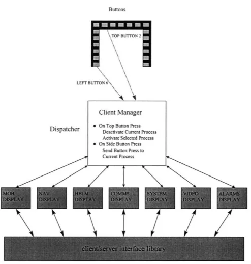
The structuring of the GUI as a set of independent processes necessitated a central
dispatcher to manage them. The Client Manager was created to serve as this central
dispatcher, providing methods for launching and terminating processes and for
communicating input information to them. In creating a well-defined interface for these
processes, issues of extensibility and distributed development were also addressed
because additions to the GUI can be made by following the proscribed interface.
Developer's can create GUI processes with no knowledge of other GUI programs - which
also means that additional processes can be developed in the future and seamlessly
integrated into the current GUI. The Client Manager also provides for extensibility in
terms of new input devices.
The final requirement of mutability was addressed by the Display Wizard, an
auxiliary tool for designing GUI screens. With this tool, the system does not need to be
recompiled to modify the attributes of individual instruments or the general layout of the
4.2 The Client Manager
4.2.1 Overview
In order to have all of the boat systems developed as separate processes, a central
dispatcher was needed to interface with the hardware buttons and to send appropriate
messages to the currently active system process (See Figure 4.1). That process could then
interpret the messages to carry out the functions that are associated with its left and right
side buttons. The dispatcher would also be responsible for managing the execution and
termination of the system processes when appropriate. This overall governing component
of the GUI is called the Client Manager because each of these individual processes can be
viewed as clients within the GUI.
The Client Manager provides three main services. It can launch client programs
that are not currently running, it allows the user to switch between client programs
seamlessly, and it forwards input messages to the currently active client for interpretation
within its scope. All of this is accomplished through an interface that all Client programs
Buttons
LEFT
Client Manager
-Dispatcher * On Top Button Press Deactivate Current Process Activate Selected Process * On Side Button Press
Send Button Press to Current Process
I
/
Figure 4.1 -Overall IBS GUI Design.
In order for a particular Client program to be launched, several things must be
done. First, the Client must be specified with a system name and executable name in a
data file read by the Client Manager on startup. The system name is placed on one the
seven top row buttons and when that button is pressed, the executable specified is
launched. Next, when the Client program initiates, it must register itself with the Client
Manager. This gives the Client Manager a handle to the process which it can use to post
In order to switch between multiple Clients, the Client Manager keeps track of
which Client program has focus. The Client that is currently active and visible to the user
is considered to have focus while those hidden do not. When a Client is launched it is
given focus and only one Client has focus at any given time. After that point, a Client
gains focus whenever the top row button associated with it is pressed. At the same time,
the program that last had focus, loses it. All of this is accomplished through two
messages, LoseFocus, which is posted to the currently active Client, and GainFocus,
posted to the Client associated with the top row button pressed. Upon receiving these
messages, it is the responsibility of the Client to iconify or restore itself as appropriate.
There are also two corresponding functions for acknowledging these messages that the
Client should call after taking these actions.
The Client Manager also sends a ButtonHit message to the Client that currently
has focus whenever one of the side buttons is pressed. A Client will only receive this
message if it has focus. The ButtonHit message specifies a parameter indicating the ID of
the button pressed. The Client is then responsible for taking appropriate action based on
this message.
The last message a Client can receive is a ShutDown message. When the Client
Manager exits, it will send this message to all registered Client programs. Each Client
should exit gracefully upon receiving this message.
There are several other functions available to the Client programs through the
Client Manager interface. Each Client has the ability to change the text that appears on
the left and right side buttons. Additionally each Client has a local stack of button texts
left and right side buttons when the Client is launched and then push its button text stack, thereby saving the texts, when a LoseFocus message is received. When the client
receives a GainFocus message, it can pop its button text stack. This will restore the
pushed texts to the buttons. Actions such as pushing or popping button text stacks should
be taken before a LoseFocus or GainFocus message is acknowledged.
4.2.2 Input Devices
During development, on-screen software buttons were used to mimic the eventual
behavior of hardware buttons. This allowed button hits to be registered through the
normal CButton Microsoft Foundation Class [20]. In order to facilitate the use of
external input devices, the interface to the client manager also allows a client to emulate a
button hit. Since any hardware buttons added to the system will require a low level
driver, this driver can simply call the button hit emulation function when appropriate.
Although the nineteen button interface is fixed, any input device can be used as a front
4.3 The GUI Clients
The individual Client programs consist of a base dialog window, hereafter referred to as
the Client Shell, a set of Display windows, and a set of instruments. Displays, contained
within the Client Shell, are the separate pages of information within the particular system.
Only one Display, maximized within the Client Shell, is visible at any given time. Each
Display then contains groups of instruments for a specific page (See Figure 4.2).
Figure 4.2 -IBS GUI Client Structure
This structure for the Clients provides a separation of functionality among the
elements that comprise them. The Client Shell is at the top level and handles all of
overall Client responsibilities, such as handling messages received from the Client
particular boat system, keeping the instruments grouped according to function. Finally,
all of the functionality necessary for drawing and updating instruments is encapsulated
within the instruments themselves. This multi-level design helps to minimize the amount
of work necessary to create additional Clients and Displays.
4.3.1 Base IBS Dialog Class - IBSClientDIg
The Client Shell for each Client is derived from a base dialog window class, IBSClntDlg.
In effect, the Client Shell's relationship with the Displays is similar to the Client
Manager's relationship with the Client in that it controls which Display is currently
visible and what information that Display receives. In addition, the Client Shell is the
container for all of the Client's Displays and attends to all of the Client's overall
responsibilities. It handles messages received from the Client Manager, obtains data from
the Server necessary for drawing its Displays, and executes appropriate button press
functions.
There are four messages from the Client Manager, described in the Client
Manager section, that the Client Shell must handle: LoseFocus, GainFocus, ButtonPress,
and ShutDown. When the Client program receives a LoseFocus message, the Client Shell
pushes its button text stack, iconifies itself, and then acknowledges the LoseFocus
message. Similarly, when it receives a GainFocus message, the Client Shell pops its
call to an analogous button press function. The Client Shell has functions for each of the
left and right side buttons. These button functions are overridden in the child classes
derived for each Client program so as to provide Client specific functionality. The
ShutDown message causes the Client Shell to exit and the Client program to terminate. Data is generally obtained from the Server by the Client Shell through a polling
routine which is launched as a separate thread. This is done at the Client Shell level
rather than the Display or instrument level so as to minimize repeated calls to the Server.
At a specified frequency, determined by a developer-defined wait time in milliseconds,
the thread calls an Update function, overridable in the derived classes. This Update
function calls the appropriate interface library functions (See Chapter 3) and does any
parsing of the returned data that may be necessary. Each time the Server is polled, the
Client Shell instructs the currently visible Display to update itself. Each instrument
within the currently visible Display is then responsible for redrawing itself based on the
new data.
4.3.2 Display Class
All of the instruments for the IBS GUI are drawn using OpenGL drawing commands [2].
The Display Class is a window class that supports such commands. It's only purpose is
to serve as a container for the groups of instruments. As a derivative of the base window
4.3.3 Instrumentation
All instruments are derived from a base instrument class that provides for common traits
and functionality. Common to all instruments are traits such as location (x and y screen
coordinates), scale, and color. The base instrument class also has a Data Pointer that
points to the variable (hereafter referred to as the Data Variable) containing the data that
the particular instrument is monitoring. This parameter, which in most cases determines
an instrument's state, can be of any basic type (integer, float, etc.) or an array of integers,
characters, or strings.
The base instrument class also includes a number of general functions necessary
for all instrument types. These include functions for creation, initialization, modification,
data input, and drawing. All but Create are implemented as virtual functions, called from
the base class as necessary. Instrument specific code that will be carried out
automatically can be written for any derived classes. The Draw functions for the derived
instruments make use of OpenGL drawing commands [2].
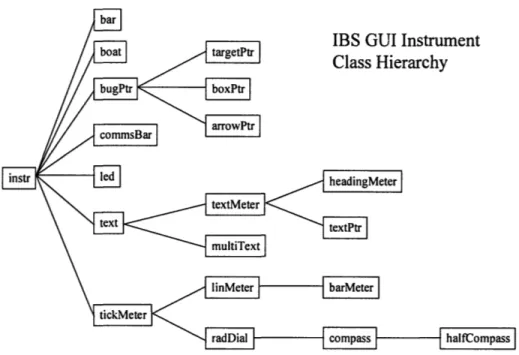
The library of instruments derived from this base class is shown in Figure 4.3 and
LBS GUI Instrument
Class Hierarchy
Figure 4.3 -IBS GUI Instrument Class Hierarchy
4.3.3.1 Static Text Class
The static text class allows for the display of a piece of static text in a Display. The class
provides for labels, messages, and on screen instructions.
4.3.3.2 MultiText Class
A MultiText is an extension of the text class that allows a piece of text to change based
on an index variable. An array of possible texts is specified and the Data Variable is an
4.3.3.3 Text Meter and Text Pointer Classes
A Text Meter is an item of text that is tied directly to a piece of data. The Data Variable
for this instrument type can be of any basic data type. The value stored in this variable
will be written as text, based on a format string specified in the same manner as for the
standard ANSI C "printf' function.
A Text Pointer is simply a Text Meter that moves over a specified distance as its
Data Variable changes. While the Text Meter can be optionally boxed, the Text Pointer
is automatically boxed with a triangle pointing left or right as desired (See Figure 4.4 at
the end of the chapter).
4.3.3.4 Linear Meter and Bar Meter Classes
A Linear Meter is a gauge whose physical representation is a box, oriented horizontally
or vertically, that is used to display a single parameter on a linear scale. A Bar Meter (a
basic bar graph), derived from the Linear Meter class (See Figure 4.5), is the most
utilized instrument for this application. A Bar Meter allows for a number of
customizations including specifications for range of data and critical zones and
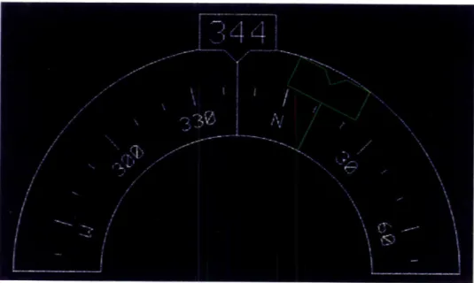
4.3.3.5 Radial Dial and Compass Classes
The Radial Dial class provides for the display of information in radial style gauges. In
this sense the gauge would be static with some type of indicator that marked the current
value of the data. The two compass instruments developed for IBS - full and half rosettes (See Figures 4.6 and 4.7) - are extensions of this class. In addition to an indicator, which for a magnetic heading compass indicates the current course to steer, the
gauges themselves rotate based on current heading.
4.3.3.6 LED Class
The LED class is useful for any data with a binary state, for example on or off. It can be
configured to display any color for each of the two states. It also provides several
possible icons for the LED including a general circular LED and several IBS specific
4.3.3.7 Bug/Pointer Class
The bugPtr class offers a base class for creating any type of pointing object and have
certain attributes such as a focus point (See Figure 4.9). The derived classes are required
to specify how the pointer is drawn. The arrowPtr class is an example of such a derived
class that is drawn as an arrow that can be used to point out an area of interest.
4.3.3.8 Other Instrument Classes
Several other classes of instruments have been developed to address IBS specific needs.
Among these are a class for drawing the outline of particular boat used to show relative
location of lights and bilge pumps and the bar class that is used to draw the bar in a Bar
4.3.4 The Display Wizard
Although it is possible to create and then freeze a specification for other applications, it is
impossible to form a "stable" specification for a user interface. There is simply no
complete checklist of rules [6]. Therefore, a GUI should be mutable in that it should
allow any changes to any non-critical aspect of the display (i.e. colors, layouts, etc.) that
may arise through user testing and feedback. Although incorporating mutability requires
a larger initial time commitment, it accelerates the development process because the
design can be continually reviewed and modified based on, for example, user community
feedback. This versatility was necessary in IBS for modifications to the appearances of
instruments to be easily accomplished. In order to meet this goal, almost every aspect of
each instrument class is represented by a member variable that can be modified to obtain
a different look or effect.
The management of such a large set of configuration variables becomes
increasingly difficult. If the developer wishes to change the color of the bar in a Bar
Meter from blue to green to see how it looks, finding the appropriate variable in the code
and recompiling the system just to see this simple change is tremendously time
consuming. To simplify this process an auxiliary development tool was created - the
Display Wizard. The Display Wizard allows the developer to design and build a display,
instruments as she wishes, configure and manipulate them, or delete them. Once the
developer is satisfied with the display, she can save the information to a data file. This
data file can then be loaded into the IBS GUI for the appropriate display which will be
Figure 4.4 -Text Meter and Text Pointer
Figure 4.6 -Compass Rosette showing heading (380) and desired heading (640)
Figure 4.7 -Half Rosette showing heading (3440) and desired heading (110)
Figure 4.8 -Simple, Compass, Nav Light, and Spot Light LEDs
Chapter
5 -
GUI Development
-
Designer's Model
The designer is mostly concerned with the visual representations and interaction
mechanisms of the interface. He is influenced by both the user's conceptual model and
the programmer's model and uses them to create an effective interface [9]. The user,
however, is often unable to describe their conceptual model, even when they are directly
involved in the design process as was the case in this project. General principles for user
interface design serve as guidelines when this is the case, and have been followed for the
IBS GUI. In some cases, tradeoffs were necessary due to the specific nature of the
interface developed. These cases are discussed in detail in the following sections.
5.1 Requirements
Many of the design goals common among graphical user interfaces also apply to the IBS
GUI and are described below [12]. The manner in which each of these principles is
addressed in the IBS GUI is described in the next section.
Clarity - The interface must be clear in visual appearance and words and text
* Comprehensibility - The interface should be intuitive, flowing in a
meaningful order. Steps to complete a task should be obvious and predictable.
* Consistency - Similar tasks and representations should be consistent
throughout the interface. Unnecessary variety requires more training time,
more specialized knowledge, and more frequent changes in procedure. A
consistent interface will encourage the development of behavior patterns [11 ].
* Control - The user should feel that they are in charge and that the system is
responding to their actions rather than the other way around.
* Efficiency - Eye and hand movements should not be wasted. The user's
attention should be captured by relevant elements when appropriate.
* Forgiving - People will make mistakes, the system should tolerate these
errors.
* Simplicity - Never include unnecessary complexity.
5.2
Implemented Clients
Several standards and guidelines were established for the implemented GUI
Clients to address the issues mentioned in the previous section. These include standards
for button functionality, inter-process consistency, and the display and acquisition of
The functionality of the buttons is established as follows: The top row buttons
serve as menus for each of the GUI Clients. Within each Client, the left buttons serve as
subsystem menus and the right buttons serve as functions within these subsystems. This
paradigm contributes to both the consistency and the comprehensibility of the system
because with any GUI Client the interface is the same. The user can quickly become
attuned to this interface and begin to accomplish tasks intuitively. This interface also
puts the user in control, allowing them to switch between the GUI Clients at any time,
regardless of his position or state within the currently focused Client.
Having only nineteen buttons, a result of the limited console space available for
mounting them, necessitated the use of modes in some cases, described in further detail in
the sections on the Clients that contain them. Modes are states in which only a limited set
of functionality is available to the user. They are generally considered to detract from the
consistency - and therefore from the usability - of a system [12]. While using modes
breaks the consistency of the interface, the tradeoff in this case is that a three button press
limit for data acquisition can be maintained throughout the system.
The three button press rule was followed in order to maintain the efficiency of the
system, allowing the user to access data quickly. This means that it only takes three
button presses to get to any data within the IBS GUI. Entering data into the system may
require more than three button hits since there is often a confirmation button to prevent
mistaken inputs. This will be explained further in the sections about the individual
Clients.
Efficiency is also improved through the use different font attributes. Data is
displayed in a lighter font. This allows the user to focus on the pertinent data quickly
without being distracted by the auxiliary information.
In order to maintain consistency as the user switches from Client to Client, each
Client remains in the state in which the user left it. The exception to this rule is that a
Client will not remain in a modal state, instead reverting to the standard interface.
Otherwise, if a Client were left in a modal state and the user returned to that Client after
some amount of time he would have to exit that modal state to be able to use the standard
interface. This method helps to alleviate user confusion.
Four GUI Clients have been developed with the framework described in Chapter 4
and these design guidelines. The Clients include an interface to the communication
systems, a Client that incorporates all of the information necessary for the driver, a
monitor for general boat systems, and a Client for handling alarms. These Clients,
together with an integrated navigation package - developed separately - comprise the
basic set of functionality necessary to operate the craft. The Figures of the different
Clients are located at the end of the Chapter. These images contain on-screen buttons that
were used during development to emulate the eventual hardware buttons.
5.2.1 COMMS Client
The COMMS Client allows the user to control any of the radios that are available on the
toggle through them using the left "Select" button (See Figures 5.1 - 5.5). A green box
highlights the currently selected radio. The attributes for each radio maintained on the
server include transmit and receive frequencies, squelch, volume, output power, power,
encryption, and modulation.
Transmit and receive frequencies, which can be controlled separately in some
radios while in others they are tied together, can be modified in two ways. Selecting
"Presets" from the left buttons causes a set of preset frequencies (in MHz) to appear on
the right buttons (See Figure 5.3). A "Page Down" key on the last right button allows for
a second page of presets or ten in all. Pushing one of these preset buttons causes the
transmit and receive frequencies to be set to the frequencies listed on the button. Since
these presets are maintained in software, all radios can have presets regardless of
whether the hardware supports such a feature. The second manner in which frequencies can be modified is to manually set the transmit and/or receive frequencies to a specific
value. This is accomplished by first pressing the left "Set Freqs" button (See Figure 5.4).
This brings up buttons on the right for manually setting frequencies and for setting up
preset values. The top right button toggles through the options for which frequency the
user wishes to set -transmit, receive, or both. The second right button brings changes to
a data entry mode where the user can type the new frequency (See Figure 5.5). A
separate mode is needed in order to have ten buttons for entering the digits 0-9
-displayed on the first five buttons on the left and right - a "Cancel" button on the bottom
left button, and an "OK" button on the bottom right button. The interface is similar to a
Bank ATM in that as the digits are pressed, the numbers scroll to the left. If the value
mode ended when the user presses "OK." Presets are set in a similar manner using the
bottom three right buttons. The only additional action necessary is for the user to choose
which preset will be modified by toggling through the them with the fifth right button.
Volume, squelch, and output power are represented by the three bar graphs
beneath the frequencies. These can be modified by first pushing the left "Volume" button
and manipulating the up and down buttons for each attribute that appear on the right (See
Figure 5.2).
The COMMS interface also incorporates controls for individual radio power,
encryption, and modulation. Pressing the last left button labeled "Control" brings up
controls on the right for each of these attributes (See Figure 5.1). Power and encryption
are two-position switches while the modulation button allows the user to toggle through
all of the possible modulations for the selected radio.
Finally, the COMMS Client allows the user to specify up to five radios to which
he will listen and one radio through which he will talk. The red arrow points to the radio
that is currently selected for talking and the left "PTT" button, or Push to Talk, toggles
through the available radios. To monitor a radio, the user presses the left "Control"
button and then the "Monitor" button on the right. This toggles monitoring on and off for
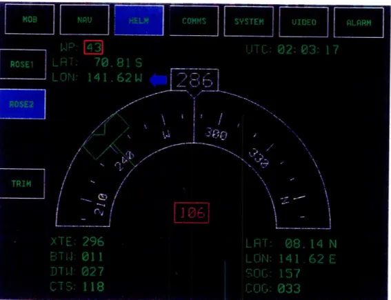
5.2.2 HELM Client
The HELM Client provides all of the monitoring information necessary for the driver of
the vessel. It consists of three screens: a full compass rosette, a half rosette, and a screen
for monitoring drive and trim tabs (See Figures 5.6 - 5.11). The full and half rosette pages display essentially the same information in two different formats.
In addition to current heading, each of the compass pages also contains other
pertinent navigation information. Each compass includes reciprocal heading - 180
degrees opposite current heading - a green course-to-steer indicator, and two blue arrows indicating direction to steer. The left side of these pages holds information about the
current waypoint or target. The upper left comer contains the ID for the current waypoint
and its latitude and longitude. The lower left displays cross track error (XTE), bearing to
waypoint (BTW), distance to waypoint (DTW), and course to steer (CTS). The right side
of the page displays status information for the vessel. In the upper right is the current
time and in the lower right are the vessel's latitude and longitude, its speed over ground
(SOG), and its course over ground (COG). All of the data displayed is obtained from the
server which is responsible for maintaining this information.
The drive and trim tabs page offers an abbreviated set of information providing
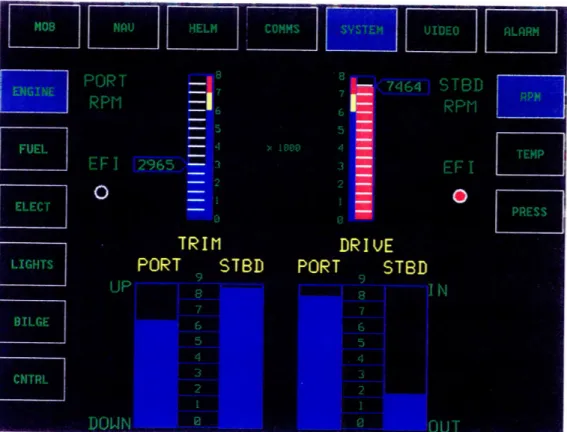
5.2.3 SYSTEM Client
The SYSTEM Client incorporates most of the boat specific systems. This Client will
vary from vessel to vessel to reflect each boat's configurations. The current SYSTEM
Client is tailored to the HSAC, which has two engines, starboard and port, and two fuel
tanks, forward and aft, for each engine.
Three engines status pages provide all of the information regarding the state of
these components. The first page, available by pressing the left "Engine" button and the
right "Rpm" button shows the rpms for each of the engines as well as the drive and trim
tabs that were included in the HELM Client (See Figures 5.12 and 5.13). Additionally,
each engine has a binary EFI, or Electronic Fuel Injection, indicator.
The other two Engine pages display information regarding water, oil, and
transmission fluid temperatures and pressures. These pages are accessed by pressing the
left "Engine" button and then either the right "Temp" button for temperatures or the right
"Press" button for pressures (See Figures 5.14 - 5.17). Each of the pages is divided into
port engine information on the top and starboard engine information on the bottom. The
EFI indicators are also displayed on these pages.
Information regarding the fuel level is available by pressing the left "Fuel" button
(See Figures 5.18 and 5.19). This page is also divided into port engine information on
- for both forward and aft tanks, fuel pressure, and rate of fuel flow are listed for each
engine. This page also provides two buttons on the right for toggling on and off the
primary and secondary fuel pumps.
Pressing the left "Elect" button brings up the status for the port and starboard
batteries and inverters (See Figures 5.20 and 5.21).
The left "Bilge" button brings up an icon of the vessel with three buttons on the
right for controlling the forward, cockpit, and engine bilge pumps (See Figure 5.22). By
default these pumps are in "auto" mode meaning that they should turn on as necessary.
Pressing the right buttons manually turns on the pumps. Pressing the right buttons again
switches the pumps back into "auto" mode.
The left "Lights" and "Control" buttons deserve special mention because these are
two cases where the physical limitation of nineteen buttons necessitated the use of modes.
The Lights page allows the user to turn on and off the light systems on the vessel while
the Control page allows the user to toggle any of the electrical relays. The standard
interface for these pages would be for the six right buttons to control the lights and relays.
In each case, however, there are more than six items that can be toggled. Using scrolling
or paging buttons would limit the number of lights or relays that could be displayed at a
time to four. As a result, toggling many of the lights and relays would require multiple
extra button hits just to find the desired switch. Instead, separate modes for lights and
controls were created, allowing these pages utilize both the left and right side buttons to
list the lights and relays. Included on each page is a "Done" button to end the mode and
The Lights page displays two icons of the boat, one on the left for interior lights
and one on the right for exterior lights (See Figure 5.23). The boat icons show the true
state of the lights on the boat. As the user presses the left and right buttons associated
with lights on the ship, the state of the buttons will change verifying the user's selection
(See Figure 5.24). This will not change the state of the lights on the boat. Lights will
only be toggled when the user presses the right "Commit" button (See Figure 5.25).
Conversely, if the user presses the right "Cancel" button, the buttons revert to the state
shown in the boat icons. A red "changed" text message pops up over the boat icons if the
true state of the lights and the state set by the users does not match, indicating that the
user should either commit or cancel their settings. The Lights page is designed in this
manner so as to prevent incorrect light selections from jeopardizing mission critical
situations.
The Control page (See Figure 5.26) lists ten different power relays that can be
turned on or off. As opposed to the "Lights" page, these switches do not require
confirmation. The right "Done" button returns to the SYSTEM standard interface and the
last left button allows the user to exit the IBS GUI (See Figure 5.27).
5.2.4 ALARMS Client
A set of specified "safe" ranges is maintained on the server. When the server detects that
for these alarms, signaling to the user that an alarm has occurred by turning the Alarm
button in the top row red. Switching to the ALARMS Client, the user sees a list of
currently active alarms (See Figure 5.28). Up to six alarms are visible on the screen at a
time. If there are more than six alarms active the fifth and six right buttons scroll the list
up and down. Pushing one of the left buttons selects the alarm that is opposite that button
(See Figure 5.29).
When an alarm has been selected, any of three actions may be taken. The alarm
may be canceled, in which case it is removed from the list of active alarms. It may be
acknowledged, causing the alarm to be removed from the list and the threshold that was
violated, causing the alarm to be signaled, is extended. Finally, the user may choose "Go
To." This action brings up the GUI page that contains the monitor for the data that
caused the alarm. The indicator of the instrument that is monitoring the critical data turns
red when an alarm is signaled.
If the user leaves the ALARMS Client, either by pressing "Go To" or by manually
selecting another Client, and there are alarms still active, the Alarm button in the top row
turns yellow to remind the user. If a new alarm is signaled, the Alarm button again turns
red signifying that a new alarm has been raised.
Because alarms have unique functionality, a few exceptions to the normal
operation of a Client had to be made. The Client Manager is designed to create a
complete separation of the GUI Clients. This allows the Clients to be developed
independently with no knowledge of each other. For the alarm Client to execute a "Go
To" command, however, it must have knowledge of the other Clients. Since the Client
stores this information as a series of button hits associated with a particular alarm. When
the "Go To" button is pressed, a set of button hits is emulated taking the user to the
appropriate page in the GUI. This information must be specified for every alarm that can
be raised and is maintained on the Server to guarantee system-wide consistency.
In keeping with the idea of completely separate Clients, only the currently focused
Client should be able to affect the buttons (i.e. change the button texts, highlight a
particular button, etc.). This would guarantee that when a Client is focused, it has
complete control and cannot be preempted by the actions of other Clients. The ALARMS
Client, however, must be able to change the last top button red when it does not have
focus in order to signal an alarm to the user. In order to accommodate this need,
unfocused Clients were given the ability to change the state of a button - background
color, highlighted or not, and multiline or not - but not the text of a button. This tradeoff,
while necessary for the ALARMS Client to function, can cause unwanted effects if used
Figure 5.1 -COMMS Client, Control Page
2000 4 N
Figure 5.2 -COMMS Client, Volume Page
[ 20. 000,
1 20 00 MA
3ill II IllljII IIMI
_ I I I · I r I I I20.000 MHz
· II II IL~I I j · II II IILI` IIII Il·lr10 40"M~
Figure 5.3 -COMMS Client, Preset Select Page
1IWT MzIZ4
Figure 5.4 -COMMS Client, Set Frequencies Page
1
10.000~
Iiriiiirrl 1lIIIII1I1 II II II·II.I 1
.0 0 M z
_IIII IIIIIHI WWWWW1
I
!I Ir CLI LL]Figure 5.5 -COMMS Client Set Frequencies Dialog
~II I ri IIII
Figure 5.6 -HELM Client, Full Rosette Page #1
Figure 5.8 -HELM Client, Half Rosette #2
Figure 5.10
-
HELM Client, Trim Page #1
Figure 5.11 -HELM Client, Trim Page #2
TR
M---POT
SB OT SB
Figure 5.12 -SYSTEM Client, Engine, Rpm #1
Figure 5.14 -SYSTEM Client, Engine, Temp #1
Figure 5.16 -SYSTEM Client, Engine, Pressure #1
Figure 5.18 -SYSTEM Client, Fuel #1
Figure 5.20 -SYSTEM Client, Electrics #1
Figure 5.22 -SYSTEM Client, Bilge Pumps
Figure 5.24 -SYSTEM Client, Lights #2
Figure 5.26 -SYSTEM Client, Controls
Figure 5.28 -ALARMS Client, first alarm selected
Chapter 6 - Evaluation and Testing
It IS common In user Interface desIgn to follow a Waterfall Model begInnIng wIth a RequIrements SpecIficatIon phase followed by DesIgn, Code, Test and MaIntenance phases ThIS tends to lead to an evaluatIon centered approach, an Important step In ImprOVIng the final Interface Usually once the evaluatIon process has been reached, however, only SImple changes, such as layouts, can be made UsabIlIty of the system IS also an Important cntenon and reqUIres a more desIgn centered approach IncludIng IntervIews of users and observatIonal studIes [12] An IntegratIon of these two methods was used In the development process ofIBS (See FIgure6 1)
PrelImInary DesIgn RevIew (PDR)
ContInUIng DesIgn RevIew (CDR)
FIgure 6 1 Development and EvaluatIOn Process
Two milestones for evaluation were established for the IBS project. The first, a
Preliminary Design Review (PDR) two months from the end of the Initial Design Phase,
focused on a prototype GUI including a COMMS Client. Three months later, a
demonstration version of the system including COMMS, HELM, and SYSTEM Clients
(See Chapter 5) was delivered for a Continuing Design Review (CDR). The ALARMS Client was developed as a follow on to CDR.
In between these two larger milestones, multiple In Process Reviews (IPRs) were
held to take advantage of user input. Particularly valuable methods of evaluating user
interface designs [10], simulations were the primary focus of the IPRs. Two different
types of simulation, one using HTML and one using Microsoft PowerPoint, were used to
address different aspects of the GUI.
6.1 HTML Simulation
The first method of simulation was a series of displays in HTML format that provided a
feel for the functionality of the nineteen button interface and the flow of control of the
system in general. Each page contained a table, representing the buttons, with seven cells
across the top and six cells in two columns on the left and right. In the middle of these
cells was one large cell that held bitmaps representing the various screens of the GUI.
pages embedded in "button" cells. Navigation through this simulation was very similar
to that of the actual system. Upon review by both staff and users, this interface was
approved and work on the prototype began.
6.2 PowerPoint Simulation
Simulations of prospective screens were particularly useful in the evaluation of the IBS
GUI because imagery and symbology were relatively simple. This meant that models for
these screens could be developed and reviewed rapidly using a commercial drawing
package. Throughout the entire development process, these simulations were reviewed
by the user community and the system was revised along with their specifications.
Microsoft PowerPoint was used to create these example page layouts. With this
tool, instruments such as bar graphs, radial dials, and pointers were drawn to create a
snapshot image of how the final system could appear. These slides were then reviewed
by both staff members and users, providing insight into user needs and perceptions
6.3 Prototype System and Preliminary Design Review
A common method for GUI evaluation involves building a prototype of the final system
[10]. Although it ignores issues of reliability or extensibility a prototype can be
developed quickly and at low cost and provide insight into possible problems and
misconceptions that might otherwise arise only after the system has been completed. A
prototype of the GUI, including a COMMS Client was developed for PDR.
The evaluation process for PDR was a three step process. First, a demonstration
of the GUI prototype interfacing with a simulated server was given to both staff and
users. Following this, the GUI was integrated in a test with an engineering prototype
server. The server interfaced with physical radios to provide a true end to end test.
Finally, a meeting of both staff and users was convened to discuss the outcome of these
demonstrations.
Several items became obvious from this phase of review. From a development
point of view, it was at this point that the impact of developing the GUI Clients as
separate processes and the need to manage these processes was fully realized. The Client
Manager interface (See Section 5.2) was formulated to deal with this issue as well as
provide for the distributed development of GUI Clients.
From a user perspective point of view, system response time was a problem that