ADAPTIVELY PRESTRESSED CONCRETE STRUCTURES by
ARNDT W. NICKLISCH Diplom-Ingenieur
Technische Universitat Darmstadt, 1999
Submitted to the Department of Civil and Environmental Engineering in Partial Fulfillment of the Requirements for the Degree of
Master of Science in Civil and Environmental Engineering at the
Massachusetts Institute of Technology February 2000
@ 2000 Arndt W. Nicklisch. All rights reserved.
The author hereby grants to MIT permission to reproduce and to distribute publicly paper and electronic copies of this thesis document in whole or in part.
Signature of Author:
Department of Civil and Environmental Engineering January 14, 2000 C'
Certified by:
Professor
Jerome J. Connor of Civil and Environmental Engineering Thesis Supervisor
Accepted by:
MASSAH S INSTITUTE
FRTECAINOLOGY
IC
Daniele Veneziano Professor of Civil and Environmental Engineering hairman, Departmental Committee on Graduate Studies
ADAPTIVELY PRESTRESSED CONCRETE STRUCTURES
by
ARNDT W. NIcKLISCH
Submitted to the Department of Civil and Environmental Engineering on January 14, 2000 in Partial Fulfillment of the Requirements
for the Degree of Master of Science in Civil and Environmental Engineering
ABSTRACT
Passive structures react effectively to only one dominant loading condition. Adaptive structures in contrast can deal with multiple loading conditions and unanticipated events at the same time. Truly adaptive civil structures do not exist. Concrete structures can be made adaptive through variable prestressing. Design concepts for an adaptive prestressed concrete girder are formulated in this research. Loading conditions and desired capabilities of the proposed system are defined. The system architecture is composed of sensors, a monitoring and control scheme, and actuators. These system components perform state identification, decision-making, and implementation of actions. Each system component is assigned requirements that are necessary to deal with all loading conditions in an appropriate way. Existing sensor technologies are explained and evaluated with respect to their capabilities to fulfill their functional requirements. A monitoring scheme is designed to interpret data assessed by the sensors for state identification. Adaptive control systems cannot be designed with conventional control algorithms. New control decision systems such as neural nets, expert systems, and fuzzy logic systems are needed for this task. Here, these systems are presented in general as forms of adaptive control. For each loading condition of the proposed system, a control strategy is developed. For the control of fluctuating live loads, a fuzzy logic based control scheme is proposed. Criteria for the selection of actuator technologies are given, and candidate actuator technologies are described and evaluated. Lastly, the problems associated with integrating the system components into a single system are discussed.
Thesis Supervisor: Jerome J. Connor
Acknowledgements
ACKNOWLEDGEMENTS
I wish to express my gratitude to my thesis supervisor, Professor Jerome J. Connor, without whose knowledge, ideas and encouragement this thesis would not have been possible. I am grateful to my academic advisor, Professor John B. Miller, for his guidance throughout my time at MIT. I would like to express to my appreciation to my friends at MIT and elsewhere for their friendship, their patience, the meaningful discussions and valuable contributions as well as the necessary distractions from my research. I would like to thank my fellow officers of the Civil and Environmental Engineering Students Association at MIT, where I had the opportunity to serve as the Graduate Student Representative. Finally, I would like to thank my family for their support throughout my educational career.
Table of Contents TABLE OF CONTENTS ABSTRACT 2 ACKNOWLEDGEMENTS 3 TABLE OF CONTENTS 4 1 GENERAL INTRODUCTION 6 1.1 INTRODUCTION 6 1.2 PRESTRESSED CONCRETE 8 1.3 STRUCTURAL CONTROL 9 1.3.1 PASSIVE CONTROL 9 1.3.2 ACTIVE CONTROL 10 1.3.3 ADAPTIVE CONTROL 11 2 PROBLEM FORMULATION 12 2.1 SCOPE OF RESEARCH 12 2.2 COMMERCIAL APPLICATIONS 13 2.2.1 PERMANENT STRUCTURES 13 2.2.2 CONSTRUCTION METHODS 14 2.3 SYSTEM ARCHITECTURE 16 2.4 STRUCTURAL SYSTEM 17 2.4.1 GENERAL CONSIDERATIONS 17 2.4.2 SPECIFIC PROBLEMS 20 2.5 LOADING CONDITIONS 21 2.5.1 FAILURE OF TENDON 22 2.5.2 LOSS IN PRESTRESS 23
2.5.3 FLUCTUATING LIVE LOADS 25
3 SENSORS AND MONITORING SCHEME 27
3.1 INTRODUCTION 27
3.2 MEASURING STRESS IN TENDONS 28
3.3 DETECTING DAMAGE IN TENDONS 28
3.4 OBSERVING STRESS IN CONCRETE 28
3.4.1 PROBLEMS OF MEASURING STRESS IN CONCRETE 29
3.4.2 STRAIN GAGE SENSORS 30
3.4.3 PIEZOELECTRIC STRAIN SENSORS 32
3.4.4 FIBER-OPTIC SENSORS 32
3.4.5 ACOUSTIC EMISSION 35
3.4.6 SENSOR DISTRIBUTION 37
3.5 STATE ASSESSMENT 37
3.5.1 PREDICTING FAILURE OF TENDON 37
3.5.2 IDENTIFYING Loss IN PRESTRESS 39
3.5.3 MONITORING LOADS 40
3.6 EVALUATION OF SENSORS AND STATE ASSESSMENT TECHNOLOGY 43
4 CONTROL SCHEME 45
Table of Contents
4.2 ADAPTIVE CONTROL SYSTEMS 45
4.2.1 NEURAL NETS 47
4.2.2 KNOWLEDGE-BASED SYSTEMS AND EXPERT SYSTEMS 50
4.2.3 FuzzY LOGIC SYSTEMS 52
4.2.4 COMMON FEATURES OF ADAPTIVE CONTROL SYSTEMS 60
4.3 CONTROL OF A PRESTRESSED CONCRETE GIRDER 60
4.3.1 CONTROL OF FAILURE OF TENDON 61
4.3.2 CONTROL OF Loss IN PRESTRESS 66
4.3.3 CONTROL OF FLUCTUATING LIVE LOADS 67
5 ACTUATORS 74
5.1 INTRODUCTION 74
5.2 PROBLEMS OF CONVENTIONAL PRESTRESSING DEVICES 74
5.3 SPECIFICATIONS 75
5.3.1 FORCE 75
5.3.2 DISPLACEMENT AND STROKE 76
5.3.3 VELOCITY AND REACTION TIME 76
5.3.4 EFFICIENCY 76
5.3.5 "HOLD LOAD ON POWER-OFF" 77
5.3.6 POWER SOURCE 77 5.3.7 SIZE 78 5.3.8 WEIGHT 78 5.3.9 RELIABILITY 78 5.3.10 ENVIRONMENTAL SAFETY 79 5.3.11 THERMAL EFFECTS 79 5.3.12 MAINTENANCE 79 5.3.13 COST 80 5.4 OPERATING PRINCIPLES 80 5.4.1 HYDRAULIC SYSTEMS 80
5.4.2 LINEAR ELECTRIC ACTUATORS 81
5.4.3 SHAPE-MEMORY ALLOYS 82
5.5 EVALUATION OF OPERATING PRINCIPLES 83
5.5.1 EVALUATION OF HYDRAULIC SYSTEMS 83
5.5.2 EVALUATION OF LINEAR ELECTRIC ACTUATORS 84
5.5.3 EVALUATION OF SHAPE-MEMORY ALLOYS 85
5.5.4 SELECTION OF SUITABLE ACTUATORS 87
5.6 INTEGRATION OF THE ACTUATOR INTO THE GIRDER 87
6 INTEGRATION OF COMPONENTS 89
6.1 INTRODUCTION 89
6.2 SENSORS, MONITORING SCHEME AND CONTROL SCHEME 89
6.3 CONTROL SCHEME AND ACTUATORS 90
7 SUMMARY AND CONCLUSIONS 91
7.1 ACCOMPLISHMENTS AND FUTURE GOALS 91
7.2 FUTURE OUTLOOK 92
Chapter] General Introduction
1 General Introduction
1.1 Introduction
The objective of this research is to formulate and evaluate design concepts for adaptively controlled prestressed concrete structures. The feasibility of applying this technology to infrastructure projects will be addressed throughout the research program. These applications will be primarily in buildings. This research will facilitate the use of new technology to improve society's infrastructure.
Prestressed concrete structures generally perform at a higher level than reinforced concrete structures. Their performance can be further improved by varying the prestressing force over time and adjusting it to the actual loading conditions. This is not possible with conventional prestressing systems. The aim of this research is to develop concepts for a prestressing scheme, which allows for adaptive control of the prestressing force. This system can be used either in permanent structures or during construction stages.
Permanent structures equipped with the proposed system would constitute a new category of civil structures. Up to now, civil structures are designed for only one dominant loading condition. Adaptive structures, in contrast, can react to more than one loading condition effectively and even deal with unanticipated events. They can be designed to be fail-safe. The system can also compensate losses in prestressing force due to creep, shrinkage, relaxation and other factors.
General Introduction
The system can also be used to improve the construction process. The prestressing force cannot always be applied in one step; it often has to be applied in several, smaller steps. High prestressing forces designed for high loads severely damage the structure when only small loads are acting on the structure. During construction, the prestressing force has to be increased gradually as more loads are applied. The proposed system automates this process,
by identifying the loads and adjusting the prestressing force. Time-consuming planning and
checking of construction stages becomes easier and faster.
The proposed system consists of sensors and a monitoring scheme, a control scheme, and actuators. Sensors and the monitoring scheme identify the current state of the system. The control scheme compares this information with the desired state and decides on an appropriate action to reach a more desirable state. The control scheme will be fuzzy logic based in order to be able to deal with multiple and unpredictable loading conditions. The actuators physically perform the action ordered by the control scheme, i.e. adjust the control forces to the desired levels.
Prestressed concrete has played a crucial role in the development of infrastructure, such as buildings and bridges. The proposed technology, as a further development of prestressed concrete, optimizes and extends the capabilities of existing technology. It improves the efficiency of existing systems by making use of advanced information processing and sensor technology. It introduces adaptive control to civil structures. The new technology will lead to an entirely new category of civil structures, as adaptive control is not employed in civil structures at this time.
Infrastructure is used daily by everyone, although most users do not consciously recognize this fact. The economic development of a nation depends on its infrastructure. The quality of infrastructure effects society as a whole. If infrastructure can be improved, everyone will benefit.
General Introduction
The proposed system will help to improve infrastructure by raising the performance level of structures. This can be achieved in two ways. Permanent structures will be able to perform tasks they previously were unable to perform. New and better construction methods will lead to lower prices, thus generating economic benefits. Technological developments have helped to make infrastructure more capable and more affordable and will continue to do so in the future. The potential benefits of this new technology are enormous.
1.2 Prestressed Concrete
Prestressed concrete can be seen as a form of reinforced concrete. Concrete has a high compressive strength, but its tensile strength is only a fraction of that. By adding steel in the tension zones of a member, both steel and concrete are used effectively. This is called reinforced concrete.
Prestressing takes this concept further by applying forces, which generate compressive stresses that offset the tensile stress due to the design loads. By minimizing tension in the concrete under load, the development of cracks is prevented. This way, the compressive strength of concrete can be used even in tension zones. Prestressed concrete members generally have a smaller depth than reinforced concrete members, for the same span and load. This results in a smaller weight, which can become important for supporting structures and foundations. Prestressed members are economic for long-span structures. By counteracting the load, prestressing can greatly increase the capacity of a member. For every load, there is an optimum level of prestressing in a member.
However, there are also some disadvantages to prestressed concrete. The range of loads a prestressed member can be designed for is relatively small. A member designed for high loads will not perform well without any or only small loads. A good performance for a wide range of loads can only be achieved through variable prestressing. Another disadvantage is higher cost.
1.3 Structural Control
Structural control usually focuses on motion but is not limited to it. It can also concern strength and stiffness of a structure. Structural control helps to improve the performance of structures more effectively by generating influences that minimize the negative effects of certain loads. The control can be applied as external forces or by changing the geometry or material properties of the structure. After this brief summary, different levels of structural control will be introduced, and illustrative examples are presented. The list of examples is not meant to be complete, but rather to reinforce the descriptions.
1.3.1 Passive Control
Passive control is by far the most commonly used form of structural control. It can best be defined by citing examples of passive control systems. These can be tuned mass damper systems or base isolation systems. In both cases, a change in the structure is caused by an external load. With tuned mass damper systems, an additional mass resonates out of phase with the original motion of the structure, thus reducing the structures dynamic response. Tuned mass damper systems control the motion of a structure.
A base isolation system changes the stiffness of the foundation of a structure. It isolates the
structure from the ground. That way the structure is protected from harmful ground motion and seismic excitation. While the isolation effectively protects the structure, it also causes large relative displacement of the structure in horizontal directions. Under seismic loads, these relative displacements are necessary to protect the structure. Under normal conditions, other lateral forces such as wind also cause relative displacements, when the structure is isolated from the ground. Under normal conditions, these displacements cannot be tolerated. Base isolation systems therefore only isolate the structure from the ground under seismic loads. The "activation" of the isolation is caused by relatively high seismic forces. Base isolation systems control the forces in a structure.
General Introduction
Passive systems require no external energy source to operate. They cannot adapt to unforeseen loads or conditions. A tuned mass damper system is tuned to a certain frequency, so that it is ineffective when the structure is excited with an entirely different frequency. Similarly, base isolation systems have a fixed yield point at which the structure is isolated. The yield point cannot be changed.
Prestressed Concrete Structures can also be seen as passive control systems. The prestressing force counteracts a force, thus controlling stress in the concrete. As in any passively controlled structure, the control is best fitted for one level of loading and ill suited for others. Passive control proves to be very effective for well defined loading conditions with little variation in load levels.
1.3.2 Active Control
Active control systems are a further development of passive systems. Active control requires an external source of energy. Since active control systems act externally on the structure, they require a monitoring scheme and a control mechanism. The monitoring scheme assesses the state of the structure, while the control mechanism determines, based on the information provided by the control scheme, how and when the external energy is applied. Examples of active control systems are active mass drivers and active variable stiffness systems.
An active mass driver is a mechanism that moves a mass to create a force acting on the structure. Like tuned mass dampers, active mass drivers are used to control the motion of tall buildings and other structures. However, they function in an entirely different way. Active variable stiffness systems have the ability to change the stiffness of a structure. This can be done by connecting or disconnecting braces in a moment frame. Unlike for a base isolation system, this process is actively controlled as the result of the data processing of a control mechanism and implemented by an externally generated force, not by the load itself. While passive systems allow only one response to a loading condition, the reaction of active systems can be changed and fine-tuned.
General Introduction Chapter I
Chapter] General Introduction
1.3.3 Adaptive Control
Adaptive control is a special form of active control. Adaptive systems have the ability to optimize the control parameters and adjust to unforeseen conditions. In addition to the state monitoring described for active systems, adaptive systems also monitor their own performance and change control algorithms and parameters when necessary. Adaptive systems are able to identify loading conditions, which have not been predefined. This goes beyond the recognition abilities of non-adaptive active systems. Since they can adapt to changing conditions, a precise knowledge of the physical system is not required for the control scheme. Adaptively controlled structures are also referred to as smart structures. This term is often used incorrectly for active structures in general.
Prestressed concrete structures in theory can be made active and even adaptive. Simply by changing the prestressing force, the same structure can cover a much broader range of loading conditions. Adaptive control also enables the structure to react to conditions that cannot be predicted or modeled accurately. The idea of adaptive prestressing is investigated in this work.
General Introduction
Chapter 2 Problem Formulation
2 Problem Formulation
2.1 Scope of Research
The advantages of prestressed concrete structures have been known and used for decades. The objective of this research is to find and evaluate ways to improve the performance of prestressed concrete structures by making them adaptive. As an example, a long-span girder will be considered. Later the findings can be used to apply the new technology to more complex problems.
Based on the ideas explained earlier the performance objectives of the proposed system will be defined more closely. The structural design will be specified to the necessary extent. The idea is to provide the hardware of the system. In order to create a general solution, numbers will not be defined unless necessary. This serves the purpose of true adaptivity of the system. General structural issues will be addressed. The emphasis, however, is on solving general problems, not on solving an explicit example. Actual loading conditions will be formulated. Again, as few details as possible will be specified in order to create a broad range of potential applications. The system should be able to gather all necessary data by itself and not rely on data from outside. The only data input should be in the format of universal knowledge and
rules.
Before the design of the system components, the design of the system architecture will be developed. Besides the structural hardware, the system will be comprised of sensors, a
Problem Formulation Chapter 2
monitoring scheme, a control scheme, and actuators. The system architecture determines how these elements interact and which tasks they perform. Due to the complexity of the whole problem, the elements will be dealt with separately. To design the elements effectively, their tasks have to be stated explicitly and the interfaces have to be structured. All this is part of the system architecture. The course of development might make changes of the system architecture or of the interfaces necessary. Unsolved issues with one element, however, will not delay the development of the other elements. After each design step, the results will be checked against the provisions of the system architecture and the interface. Adjustments on either side will be made. Finally, the overall achievement of all elements will be evaluated. Persisting problems or unresolved issues will be explained and included in recommendations for further research.
2.2 Commercial Applications
Any successful research will eventually have a commercial application. The new technology will only be successful and applied commercially if the technology is
Li able to perform tasks that no other technology has been able to perform before, or u more efficient than an existing technology for a particular task.
Many historic examples exist. Adaptive concrete structures are not meant to replace conventional concrete structures but to supplement them. They will eventually give designers a greater variety of design solutions to choose from. At this point, two commercial applications are seen as most likely to become real. These two applications are permanent structures and construction methods. A vision for these applications is described below.
2.2.1 Permanent Structures
The performance of permanent structures can be improved by adaptive control systems. The improvements can be in safety or in efficiency or in both. Again, using the example of a
Problem Formulation Chapter 2
prestressed concrete girder, the objectives of adaptive control can be defined as:
i Making the girder failsafe. This means the failure of a tendon can be compensated for by the rest of the system.
Li Compensating loss of prestress due to slip at the anchorages, frictional losses along the tendons, shrinkage and creep of the concrete and relaxation of the steel tendons.
i Allowing the girder to bear loads higher than design loads for passive prestressing by activating structural reserves. When a load is applied, the tension in the tendons can be higher without causing the concrete to fail. Prestressing forces are activated on demand. With increased tension the load bearing capacity also rises.
The first point addresses safety, the second point addresses efficiency and the third one a combination of safety and efficiency. Practical applications can be any structure that must be fail-safe, such as hospitals or military structures, or wherever loading conditions cannot be defined properly for the design or where failsafe performance must be guaranteed. Ultimately, the structure will have several prestressing schemes to suit the needs of multiple loading conditions in an optimal way.
2.2.2 Construction Methods
For many prestressed structures such as long-span bridges live loads only account for a small part of all loads. Using the example of the long-span bridge, the dead load is the self-weight of the girder, the bridge deck, pavement etc. The self-weight of the girder as the main structural element is only a small part of the total dead load. This causes a conflict between efficient design and structural requirements during construction stages. At the beginning of construction, the girder only bears its own self-weight and little or no other load. During construction, the dead load gradually builds up. After completion, all live and dead loads act on the girder. The same girder has to deal with two completely different loading conditions:
Problem Formulation Chapter 2
virtually no load and all dead and live loads combined. If all the dead load acted immediately, a higher tensioning force in the tendons could be applied, making a more economic design of the girder possible.
This is where the adaptive control comes in. The girder might be prefabricated or cast in place. It is equipped with a control device as described in this research. When the girder is in place, the tensioning force is relatively low since the girder is unloaded. During construction, the dead load increases in steps. Simultaneously the tension in the tendons can be increased to account for the higher load. Since the system is controlled automatically, the construction process is not obstructed and changes can be made any time. The adaptive control system adjusts itself to the course of construction. When construction has been completed, the prestressing force has reached the desired level for the total loads. Losses in prestress caused
by creep, shrinkage and relaxation that occur during construction are also compensated for.
After that, the prestressing device including the sensors, monitoring and control scheme can be removed and used on the next job. In general, a higher level of prestressing becomes possible when the problem of initial prestress is eliminated.
This application has the great advantage of simplicity. During the construction process, the load changes are quasi-static and the loads are continuously increasing. The load will only
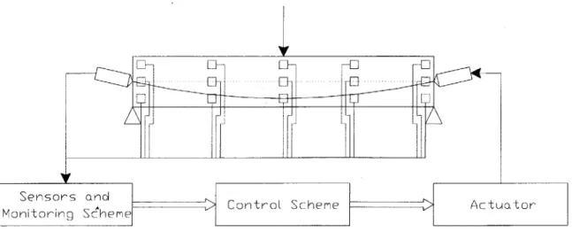
Figure 1: System Architecture
increase and will never decrease. The operating cost of the system will be low, as it will only operate for a short time during construction. After that, it can be used at other jobs, with little or no modification. Savings in construction cost can be substantial.
2.3 System Architecture
The control of the girder will be adjusted by varying the tension in the cables. According to the general scheme of Identify - Decide - Act, the system will monitor and identify its state, determine an appropriate action and transform this decision into physical changes. This will be done by sensors, a monitoring scheme, a control scheme and actuators, respectively. The general scheme of the system architecture is shown in Figure 1. The most important component is the control scheme. The control scheme will not rely on traditional algorithms, but employ adaptive control technology.
To solve engineering problems, sensors and monitoring scheme, control scheme and actuator are dealt with separately. To ensure optimal results, the components are designed independently and assembled later. Interfaces are defined so that independent design processes become possible. This strategy ensures that problems or errors in one component do not affect the designs of other components.
At this point, input and output variables have to be defined. Unlike in simple control problems, there are several variables to be observed and their values must be kept within the permissible ranges, not as close as possible to a constant value. These ranges have desirable and tolerable sections, which vary with changing conditions.
For the general definition of the problem and the dimensions of the girder, a good balance between a realistic application and a pure research project has to be found. A fully realistic approach would mean the complete development of a new product including all details. This would certainly be beyond the scope of this research. Minor problems would dominate the work and distract from the actual issue of adaptive control. On the other hand, a pure lab
Problem Formulation Chapter 2
approach would omit important engineering issues. Without addressing these engineering issues, actual applications are impossible. It would be of a pure academic interest and useless for further development. The compromise is a problem definition that focuses on the main issues of adaptive control, yet does not completely disregard related engineering problems. The engineering problems must be identified and ways to solve them must be shown. The system should be designed in a simple way, but have the potential to rise to an actual application.
2.4 Structural System
First, some general considerations regarding the structural system will be made. Then, specific problems related to the structural system are identified. The general considerations deal with issues such as the general layout of the structure, type and layout of tendons, prestressing methods and corrosion. The specific problems are caused by different assumptions for the design that become necessary due to the adaptive control of the system.
2.4.1 General Considerations
The design of the systems will be tailored to fit a long-span structure. There are two reasons for this choice. Firstly, prestressing generally is most effective for long-span structures, and secondly, the influence of shear is less important for long-span structures. Reinforced concrete girders become very heavy when reaching a span of 20 to 30 m. For girders of a larger span, prestressed concrete is more efficient, since the depth of a prestressed member usually is about 65 to 80 percent of the depth of the equivalent reinforced concrete member. Prestressing itself causes additional cost that can only be justified with savings elsewhere. For long spans, these savings are larger than the additional cost. Consequently, the use of prestressed concrete in combination with adaptive control is only efficient for long-span structures.
In a long-span structure, bending becomes critical, while shear only plays a minor role. This
Problem Formulation Chapter 2
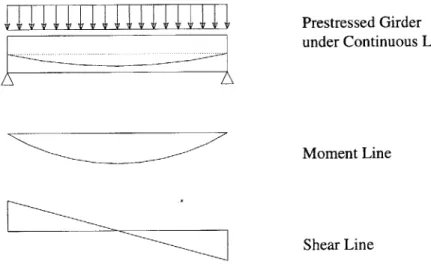
is important since prestressing controls bending rather than shear. With a longer span, point loads increase in number, but not in magnitude. Continuous loads do not increase with a longer span, but the length or area on which they act becomes larger. Assuming a continuous load, the shear force increases linearly as the span becomes larger. The moment in contrast increases quadratically. Moment and shear lines are shown in Figure 2.
Generally, a continuous load will be assumed as the dominant loading condition under normal circumstances. The loading conditions will be explained in detail later in this chapter.
Prestressed Girder under Continuous Load
Moment Line
Shear Line
Figure 2: Prestressed Girder under Continuous Load with Moment and Shear Lines
To determine the shape of the tendon, knowledge of the dominant load is necessary, since the shape of the tendon cannot be adjusted later. For a long-span member, continuous loads most closely resemble actual loading conditions. For this load, the moment line is parabolic. Hence, the shape of the tendon will also be parabolic. Another assumption that is made is that there will be no external axial loads.
The prestressing force has to be adjusted during the operation of the system. This is only possible if unbonded tendons are used. Since the rather uncommon unbonded tendons will be incorporated in the design of the system, the main differences between bonded and unbonded
Problem Formulation Chapter 2
Problem Formulation
tendons are outlined here.
An unbonded tendon is shown in Figure 3. There are two common methods of prestressing concrete. For pre-tensioning, tendons are tensioned before concrete is poured. For adaptive systems pre-tensioning methods are impractical and will not be covered here. Post-tensioning systems can either use bonded or unbonded tendons. In any case, tendons are in a duct or tube, which is placed in the concrete. After the concrete has reached sufficient strength, the tendons are tensioned. At this point, there is no bond between the tendon and the concrete. The prestressing force rests completely on the anchorages at the ends of the tendons. Because the entire force is transferred at anchorage points, these points have to receive special attention. For bonded tendons, the ducts are grouted under pressure. This creates a bond between the concrete and the tendons. Unbonded tendons are not grouted. Structurally there is one major difference between bonded and unbonded tendons. When a load is applied to the structure, boundary conditions require the load-induced strain between concrete and tendon to be the same. This means under load the tendons receive additional stress and in that way act as normal reinforcement. Unbonded tendons in contrast are independent from concrete strain. They only apply the prestressing force on the concrete. There are a number of other differences not concerning the structural function. Unbonded tendons use smaller tubes than bonded tendons in post-tensioning. They therefore can be aligned better, which improves structural efficiency. Their lower friction values help reduce frictional losses over the length of the tendon. Besides that, they are faster to install, which makes construction easier.
The problem of corrosion is the same as for any prestressed concrete structure. The tendons have to be protected to ensure the durability and long-term performance of the structure. In
Plastic tube Grease Strand
Figure 3: Unbonded Tendon as in [2]
the ducts, the tendons are protected by grease. The structures ability to change the prestressing force causes additional problems related to corrosion. Since the actuators move the tendon ends, the tendons cannot be sealed after prestressing. The tendon ends must be accessible for actuator operation. This design detail has to be included in the design of the actuator and its connection with the structure. Alternatively, the use of fiber reinforced plastic (FRP) tendons, which are corrosion free, presents another option.
2.4.2 Specific Problems
Specific problems related to the structural system arise from the active control of the system. Conventional design concepts cannot be applied. An in-depth understanding of the structural behavior becomes necessary.
Safety concepts with load factors and their strength reduction factors as used by American Concrete Institute (ACI) or the Euro Code system cannot be applied for adaptively controlled structures. The problem of multiple loading conditions, as it is often encountered with prestressed concrete structures, cannot be dealt with by the control scheme in the way a designer deals with it. A designer considers the loading conditions one by one with the appropriate load factors and designs the structure accordingly. The result often is a number of iterative steps until one design fits all loading conditions. The control scheme in contrast takes into account actual loads at any time and adjusts the structure itself to fit the loading conditions. Therefore, the control scheme can only incorporate material factors. However, the safety achieved through load factors can be including by reducing the permissible loads
by a factor, equal to the load factor. Then the overall safety level is the same as in
conventional structures. The way it is achieved is completely different. Within the permissible range of loads, the system "knows" the actual loads, making load factors obsolete. The absolute capacity of the structure is limited. For an optimal design the maximum loading must be known. In the given configuration this is often not the case. In that situation the only answer is to design the structure and then determine the ultimate capacity afterwards.
Problem Formulation Chapter 2
Consequently, for the design of the structural system and the control scheme the strength reduction factors as given in ACI 318-95 or EC 2 will be used. No load factors will be applied during the design phase or for the operation of the system. Finally, the minimum and maximum permissible load will be adjusted with the appropriate load factors.
The maximum permissible stress for concrete and tendons will be used as provided by the code from which the safety concept is adopted. Special attention has to be directed to the development of the concrete strength during hardening. The same is true for the Young's modulus. The modulus will be used to calculate stress from strain. A precise understanding of the modulus and the factors that influence it is therefore crucial. In the final state (after 28 days) the modulus can be considered linear for all practical purposes to about 40 percent of the ultimate strength
f'c
[35]. According to the American Association of State Highway andTransportation Officials (AASHTO), the maximum permissible compression stress at service loads after losses in prestress is 0.40
f'c.
Hence, if the structure is designed (and operated) according to AASHTO rules, the stress strain relation can be assumed constant after 28 days.Furthermore, the structural system and the control scheme will be designed to keep the concrete in compression at all times. This way, cracks are prevented. Cracks lead to non-linear behavior of the structure that is hard to control. Structural behavior becomes unpredictable as cracks increase in number and size. It is therefore crucial to avoid tension cracks. Besides that, the structure is expected to undergo a large number of load cycles. Fatigue problems can only be controlled, if cracks are avoided.
2.5 Loading Conditions
The general objectives of the systems capabilities have to be transformed into explicit loading conditions. Explicit in this context does not necessarily mean quantitative. Qualitative descriptions will be used wherever possible. The aim is to create scenarios that can be applied to numerous examples without requiring substantial adjustments in the
Problem Formulation Chapter 2
system. At this stage of system development, it is more important to understand the problems and to find new ways to deal with them than to perform precise calculations. As mentioned earlier, the complexity of the problem requires a separation of the key issues. One way of doing this will be the decomposition of the system into elements. Another way is to separate loading conditions. Whenever possible, unrelated loading conditions will be dealt with independently. This will primarily affect the control scheme and to a certain extent the monitoring scheme. It will be easier to find solutions for each loading condition separately.
Two loading conditions can be used to express the objective of increasing efficiency. The first one is loss in prestress, which has to be minimized. The other one is the great variation in total load to the point where a fixed cable tension can only be suitable for either minimum or maximum load. This loading condition is also part of the objective to create a failsafe structure. Making the structure failsafe also includes dealing with the failure of a tendon as a loading condition. It becomes clear that a performance objective might consist of more than one loading condition and that a loading condition might serve more than one performance objective.
Concluding from the above findings, the performance objectives (increased efficiency, failsafe operation) generate the loading conditions of loss in prestress, fluctuating levels of loads and failure of a tendon. In the following, these loading conditions will be defined and described more closely. Eventually, it might become necessary to evaluate possible combinations of these loading conditions.
2.5.1 Failure of Tendon
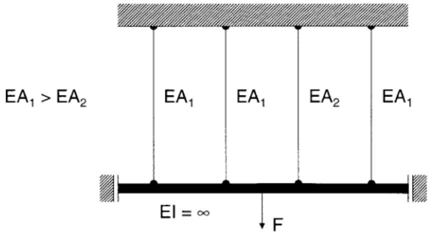
The objective of making the structure failsafe is closely related with the structure's ability to deal with the failure of a tendon. The most frequent cause of tendon failure is corrosion. Other possible causes are overload, fatigue and faulty materials. The structures ability to compensate for the failure of a tendon has the following implications. Structural reserves must be available when needed. This is possible when several parallel tendons with the same
Problem Formulation Chapter 2
Chapter 2 Problem Formulation
curvature are used. The system must first recognize the failure of a tendon. The control scheme decides on how to utilize excess capacity in the remaining tendons to ensure the continuous performance of the system. The actuators implement this action. Easy repair and replacement of the components is required to maintain the failsafe ability throughout the life of the structure. This means that tendons must be replaceable.
The system design is based on the assumption that the system is reacting only to quasi-static load changes. With the failure of a tendon, however, this cannot be achieved directly. Once a tendon fails, it fails suddenly and rapidly, not leaving much time to react. The system will not be able to react in a sufficiently short time. It is therefore crucial to detect and identify a tendon that is about to fail before the failure actually occurs, giving the system ample time to take the appropriate measures. In addition, the system has to give notice so that the damaged tendon can be replaced. Between the deactivation of the faulty tendon and its replacement, the system must exhibit the same level of performance as under normal conditions.
2.5.2 Loss in Prestress
Loss in prestress is caused by slip at anchorages, frictional losses along tendons, creep and shrinkage of concrete, elastic shortening of concrete and relaxation of the tendons. Although these sources are unrelated, they all result in the same phenomenon. To minimize their combined effect, they have to be treated separately. A this point, a note on elastic shortening seems appropriate. In post-tensioned structures, losses caused by elastic shortening in concrete occur, when several strands are prestressed sequentially. For the adaptive system, this is irrelevant since all strands will be controlled individually at all times.
Slip at anchorages is a result of the post-tensioning process. After post-tensioning or adjusting the prestressing force, the force must be transferred from the prestressing device to the anchorage. During this process, a slight inward movement of the tendon occurs and the anchorage itself deforms under stress. The amount of total movement depends on the type of anchorage. The actual anchorage design will be part of the actuator. "Standard" anchorage
systems will only be suitable with modification, if at all. However, it is safe to assume that the same anchorage will always produce the same slip. The actual loss of stress is determined
by the slip divided by the total length of the tendon and multiplied by the modulus. The loss
in short systems will therefore be greater than in systems with long tendons. In this case, the girder will be long-span and therefore have long tendons. Hence, the overall effect of slip will be small and can be quantified once the actuator has been designed. Unlike in conventional prestressed systems in the adaptive system, adjustments in the prestressing force take place in a range where a slightly higher force can be applied during prestressing. This is possible because the force is adjusted to the optimum level under current conditions, not to the ultimate level to deal with all conditions. Therefore, only in extreme situations the loss in prestress due to slip cannot be compensated for by applying a slightly higher prestressing force. Nevertheless, this has to be included in the control scheme to be functional.
Frictional losses account for another portion of loss in prestress. There are two sources of frictional losses: curvature friction and wobble friction. Curvature friction is induced by bending the profile of the tendon into the desired shape, wobble friction by misalignment of the tendon from its intended shape. Frictional losses occur along the tendons decreasing the prestressing force gradually from the jacking end to the other end of the tendon. For a straight tendon, there is no curvature friction. The amount of curvature friction depends on the angular change of the tendon and the curvature friction coefficient. In the case of this research, the angular change will be small since the profile will have a parabolic shape and the height of the girder is small in relation to its length. Wobble friction depends on the length of the tendon and the wobble friction coefficient. As mentioned, both friction coefficients are low due to the use of unbonded tendons.
Creep and shrinkage are two unrelated factors causing loss in prestress. However, they have similar effects on the prestressing force and can be seen as a single source of loss in prestress. Creep and shrinkage cause time-dependent losses. Creep is the shortening of the girder under constant axial loads over time. Shrinkage is the shortening of concrete from loss of moisture.
Problem Formulation Chapter 2
As the concrete contracts, the tendons relax and lose tension. The amount of creep and shrinkage depends on a number of factors including environmental factors. It therefore cannot be predicted exactly. As explained earlier, in this application no elastic shortening loss occurs, since all tendons are controlled individually and can be tensioned simultaneously.
Relaxation of tendons is an effect similar to creep in concrete. With creep, the stress remains constant and negative elongation becomes larger. With relaxation, elongation remains constant and stress decreases. Decreased stress means loss in tension. As creep and shrinkage, relaxation is time-dependent.
2.5.3 Fluctuating Live Loads
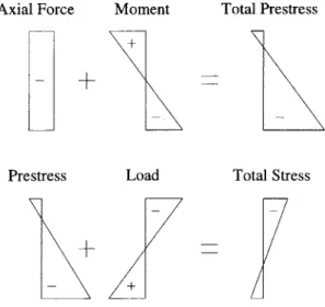
In this context, the term fluctuating live loads refers to loads and conditions that cannot be predicted and modeled as design loads or loads that exceed design load levels. For the design of prestressed concrete structures, only a small range of total loads is permissible. The same physical structure is designed for either high or low load levels, never for both. The challenge is to make the structure suitable for both loading conditions by adjusting the prestressing force to the load level. As demonstrated in Figure 4, the prestressing force has a reversing
Stress caused by
Prestressing Force
Total Stress
Axial Force Prestress Moment Load + Total Prestress Total StressFigure 4: Stress in Concrete from Prestress and Loads
effect to the load. It therefore must be adjusted carefully to the existing loads.
The adaptive nature of the system makes loads that are higher than design loads tolerable. This goes beyond the safety provided by strength reduction and load factors. In the same way the system deals with loads exceeding permissible levels, it can deal with loads that cannot be expressed as meaningful design loads. The same procedure applies for gradually
increasing loads as described for the application as a construction method.
As the bottom line, this loading condition can be described as increasing loads for a given structural system up to the absolute limit that utilizes the ultimate capacity of the system, without causing any structural damage. It also includes the reversed case of declining loads below the minimum level required for high prestressing forces.
Problem Formulation Chapter 2
Chapter 3 Sensors and Monitoring Scheme
3 Sensors and Monitoring Scheme
3.1 Introduction
Sensors and the monitoring scheme conduct the state identification of the system. The acquired data is then fed into the control scheme, which further processes it. Sensors take actual measurements at various locations. The monitoring scheme preprocesses the raw data obtained by the sensors.
To enable the control scheme to decide on an appropriate action, information on the system state must be available. It is assumed to be impossible to measure loads and determine their locations directly. The system identification has to rely on data found in the structure itself. In order to control the performance of the system, stress in the concrete and the force in the tendons must be known in real-time. The control scheme uses stress as input variables. Sensors are not able to gather this data directly. The data provided by the sensors therefore must be processed by the monitoring scheme, which transforms it into information on stress.
Knowledge of the stress state in the structure is important for the control of fluctuating loads and loss in prestress. To make the structure fail-safe, damages in tendons must be detected before they cause damage to the structure as a whole. In the following, methods of observing stress in the structure and detecting damages in tendons are presented. First, data acquisition and sensor technology is discussed; then data processing and the monitoring scheme are investigated.
Sensors and Monitoring Scheme Chapter 3
Sensors and Monitoring Scheme
3.2 Measuring Stress in Tendons
Forces in the tendons can be measured directly at the tendon ends or through fiber optic sensors integrated in the tendons. Forces in the middle section of the girder will be smaller due to frictional losses. It has to be analyzed for every individual case, if these losses can be calculated accurately enough or if the actual forces have to be measured. With the measured strain and the axial stiffness of the tendon, the axial force can be calculated. A possible defect in the tendon is assumed not to occur directly at the end, where the measurement is taken. This assumption is reasonable, since damages are mostly caused by corrosion. Corrosion occurs first at locations with the smallest concrete cover, which is in the middle of the girder. The measured stress at the end of the tendon is therefore correct for damaged tendons as well.
3.3 Detecting Damage in Tendons
A new method to identify damaged tendons in prestressed structures has been developed by
Pure Technologies Inc. of Calgary, Canada [42]. Sensors "listen" to the structure, as breaking wires in tendons emit sounds. The method is non-destructive and does not interfere with the behavior of the structure. With this acoustic data, damaged tendons can be spotted. Before evaluation, the data has to be filtered from background noise present in the structure from other events such as traffic.
3.4 Observing Stress in Concrete
In the following, several sensors and measurement methods are presented. As explained before, either stress or strain will be observed. At this point sensor technologies and problems associated with them will be explained. The integration with the monitoring scheme and in the system as a whole will be done later as a description of schemes for state assessment.
Chapter 3 Sensors and Monitoring Scheme
3.4.1 Problems of Measuring Stress in Concrete
Stress is difficult to measure directly, especially in concrete. The alternative is to measure strain and compute the stress from there. Strain in concrete can be measured easily. Using strain measurements and the stress-strain relation, stress can be calculated. However, there are several problems inherent to this procedure. The stress-strain relation for concrete is difficult to establish. Besides that, strain has components, which are not stress-induced and thus yield misleading measurements. These components may be caused by creep, shrinkage or temperature effects. Only stress-induced strain is relevant for the control of the system.
The stress-strain relation usually is expressed as the modulus. As demonstrated in Figure 5 the actual stress-strain relation is different from the assumptions made for the modulus. The stress-strain relation is also a function of concrete strength and of time especially at an early concrete age. The stress-strain relation based on the modulus is therefore not accurate enough for exact control purposes.
Calculating stress from strain is not the only problem. Several factors other than stress can also cause strain. The influence of these factors on strain is explained in the following. A solution to these problems will be established later on.
FE a
Figure 5: Actual and Assumed Stress-Strain Relations in Concrete
Changes in temperature cause strain without causing stress. When the temperature of a structure or an element changes, it expands or contracts. Expansion and contraction are equivalents of strain. In an unconstrained structure, there is no stress associated with strain. If expansion or contraction is fully or partly restrained, the inhibited portion of the strain transforms into stress. Temperature compensation with sensors will be explained later.
Shrinkage causes strain in the concrete without causing stress. Creep causes problems similar to those caused by shrinkage. Shrinkage is influenced by the concrete mix and by environmental conditions. Creep is mainly influenced by loads. The magnitude of strain caused by creep and shrinkage can be much larger than that of stress-induced strain. While the total strain from creep and shrinkage can be calculated or predicted with some accuracy, the prediction or calculation of the development of creep and shrinkage over time - although possible - is not precise enough to yield meaningful results. Since the control system is supposed to operate during the construction phase, levels of creep and shrinkage are expected to change greatly. A small error in predicted effects of creep and shrinkage will cause a large, intolerable error in the prediction of stress-induced strain. It is therefore necessary to obtain up-to-date information on stress-induced strain directly, not by relying on predictions. During the first hours after concreting, concrete develops heat, which causes thermal expansion. Over time, the temperature drops to the level of the surrounding environment. This is called thermal expansion. Thermal expansion is neither uniform nor can it be measured exactly. During the first stages of construction, it can greatly disturb the results of strain measurement.
3.4.2 Strain Gage Sensors
Strain gage sensors are based on changing conductivity in materials when mechanically strained. This is called the piezoresistive effect. Strain gages are stamp-sized sensors that are applied externally to the surface of a structure. The components of these sensors are grid, matrix, adhesive and protective cover. The grid represents the actual sensor element. The grid
Sensors and Monitoring Scheme Chapter 3
Sensors and Monitoring Scheme
is a resistor material, which is connected to an electrical circuit. The resistivity of the grid is related to the stress in the grid. It is the sensor output. The resistor materials are metallic or semiconducting. The most commonly used metals are alloys constantan, nichrome, advance and karma [15]. As semiconducting material, silicon is used. The matrix, also called carrier, transfers the strain in the testing object to the grid and provides electrical isolation. The adhesive couples the strain from the testing object to the matrix. The protective cover shields the grid from environmental factors and mechanical impact.
Strain gages can be categorized by grid into wire strain gages, foil strain gages, thin- and thick-film strain gages [19]. Wire strain gages use a metal wire as grid, which is shown in Figure 6. In foil strain gages, the wire is replaced with a metal foil. Thin-film stain gages have a vacuum-deposited film of metallic or semiconducting material as grid [19]. Thick-film strain gages are produced in a complex process, which results in a compact, conducting, viscous mass on the matrix with a thickness of 20-25 gm.
In civil engineering, wire strain gages are commonly used for lab applications. Their popularity stems from their easy use, accurate measurement and low cost. However, for lab applications durability and long-term performance are seldom an issue. Their performance in these areas is therefore questionable. Another setback is the limitation to external application only. Strain gage sensors cannot be embedded in the structure, but have to be applied externally.
Matrix Grid
Figure 6: Wire Strain Gage
3.4.3 Piezoelectric Strain Sensors
Piezoelectric sensors exhibit a similar schematic design as strain gage sensors. Instead of the piezoresistive effect, they utilize the piezoelectric effect. The metallic or semiconducting material in strain gage sensors is replaced with a crystalline material in piezoelectric sensors. The piezoelectric effect is the generation of an electric charge in certain materials when strained. These piezoelectric materials are crystal, ceramic and polymeric materials. Examples of crystals, ceramics and polymers are quartz (SiO2), PZT (lead circonate titanate)
and PVDF (polyvinylidene fluoride), respectively. The material is applied as a film on a backing layer, which is connected to the testing object to conduct strain. When strained, the film generates an electric charge. This electric signal is the sensor output. Very simple sensors generate an output only when subject to a changing stimulus and produce no output for constant strain.
Piezoelectric sensors appear to be an equally practical solution as strain gage sensors. However, their price is likely to be much higher. Their advantages over strain gage sensors have yet to be validated. Nevertheless, they remain a technically viable alternative.
3.4.4 Fiber-Optic Sensors
A relatively new way of measuring strain in concrete structures is the application of
fiber-optic sensors. Fiber-fiber-optic sensors have no common operating principle. Their common
>8mm - >5mm 25to 40 nm
-Outer Jacket
KevIar Inner Jacket
Reinforcing Fibres (Tight or Loose) Fibre Buffer
Figure 7: Structure of Fiber-Optic Sensor as in [52]
feature is an optic fiber through which light is transmitted. The modulation of the light is measured as the output signal. The structure of a fiber-optic sensor is given in Figure 7.
Fiber-optic sensors can be categorized in a number of different ways, reflecting different operating principles. Possible categorizations are intrinsic or extrinsic, point, distributed or multiplexed sensors as well as intensiometric or interferometric. In intrinsic fiber-optic sensors, the modulation of the light, which represents the signal, happens inside the fiber. With extrinsic fiber-optic sensors, it happens outside. Measurements along the fiber can be taken at single location, which is called point sensor. Distributed sensing is the measurement of the average strain over a certain length along the fiber. The third option is to arrange several point sensors along a single fiber, which is called multiplexed or quasi-distributed sensing. Intensiometric sensors use the amount of light transferred through the fiber as the only variable, with on-off signals being the simplest form. Sensors using more sophisticated sensing methods are called interferometric sensors. Fiber-optic sensors can be embedded in the concrete or applied on or near the surface. So-called single ended fibers have to be accessible from one end only by combining source and reception of light at the same end.
In the following, two frequently used sensor types - fiber Bragg grating sensors and Fabry-Perot sensors - are presented. Both sensor types are recommended for concrete structures in [52]. Fiber Brag grating sensors reflect a portion of light, indicating a change in strain by a shift in the wavelength of the reflected light. The refection is caused by a series of physically altered, precisely spaced regions in the core of the fiber. This change in physical properties, the index of refraction in particular, is produced by the application of UV light. The spacing of the altered regions, called the pitch, determines the reflective properties of the sensor. Strain causes a change in the pitch, thus results in a different wavelength of the reflected light. Most of the light, however, is transmitted and can be used for other sensors located along the fiber. The fact that fiber Bragg grating sensors rely on wavelength as the only parameter makes them easy to use as they require no calibration. The operating principle of fiber Bragg grating sensors is shown in Figure 8.
Sensors and Monitoring Scheme Chapter 3
Chapter 3 Sensors and Monitoring Scheme
Optical Fibre Grating Sensor
S
x RI
} } T C 0 .9 O'U 'a) E CI) __Figure 8: Operating Principle of Fiber Bragg Grating Sensors as in [52]
Fabry-Perot sensors feature a gap, called cavity, between two reflecting fiber ends. They use a white light broadband source to measure a dimensional gap shift. The two fiber ends are enclosed in a glass capillary for protection. Fabry-Perot sensors can be temperature compensated or compensated. Their operating principles for compensated and non-compensated versions are shown in Figure 9.
Table I represents a list of desirable characteristics for fiber-optic sensors for strain measurement in civil structures adopted from [32] and how fiber Bragg grating sensors and
Table 1: Desirable Characteristics of Fiber-Optic Sensors
Characteristics Fiber Bragg Fabry-Perot
Grating Sensors Sensors
linear response 0
single ended
insensitive to thermal fluctuations temperature compensated
capable of absolute measurement 0 0
nonperturbative to the structure 0
e
immune to power interruption 0 0
able to multiplex
easy to mass produce _
X
Sensors and Monitoring Scheme Chapter 3
Sensors and Monitoring Scheme
Fabry-Perot sensors match these characteristics. Other factors such as durability are not fully known. According to reports, durability has been demonstrated for five years, but not for the entire life cycle of a structure of 50 or more years [32]. At this stage of product development, a durability of five year is sufficient.
Summarizing, the advantages of fiber Bragg grating sensors are the possibility of multiplexed sensors (several sensors along a single fiber) and the lack of a calibration requirement. Fabry-Perot sensors in contrast can be temperature compensated. They also require no calibration.
Incoming Fibre
Metallic Fibre Cavity Length
Incoming Fibre Gauge
Length-II
Cavity Length
Micro Capillary
Figure 9: Fabry-Perot Sensors, Compensated (top), Non-Compensated (bottom) [52]
Both sensor types can be embedded in the concrete structure and are available in versions that withstand the adverse chemical and mechanical environment in concrete for a sufficiently long period of operation.
3.4.5 Acoustic Emission
Acoustic emission is a method for the direct measurement of stress. If the method proves workable for this application, it eliminates problems related to strain measurement. A formal
200
![Figure 3: Unbonded Tendon as in [2]](https://thumb-eu.123doks.com/thumbv2/123doknet/13866371.445954/19.918.277.631.925.1033/figure-unbonded-tendon.webp)


![Figure 7: Structure of Fiber-Optic Sensor as in [52]](https://thumb-eu.123doks.com/thumbv2/123doknet/13866371.445954/32.918.209.712.875.1027/figure-structure-fiber-optic-sensor.webp)
![Figure 8: Operating Principle of Fiber Bragg Grating Sensors as in [52]](https://thumb-eu.123doks.com/thumbv2/123doknet/13866371.445954/34.918.226.682.157.430/figure-operating-principle-fiber-bragg-grating-sensors.webp)
![Figure 9: Fabry-Perot Sensors, Compensated (top), Non-Compensated (bottom) [52]](https://thumb-eu.123doks.com/thumbv2/123doknet/13866371.445954/35.918.285.629.407.753/figure-fabry-perot-sensors-compensated-non-compensated.webp)