Building Dependability Arguments for Software
Intensive Systems
by
Robert Morrison Seater
B.S., Haverford College (2002)
M.S., Massachusetts Institute of Technology (2005)
Submitted to the Department of Electrical Engineering and Computer
Science
in partial fulfillment of the requirements for the degree of
Doctor of Philosophy
at the
MASSACHUSETTS INSTITUTE OF TECHNOLOGY
February 2009
@
Massachusetts Institute of Technology 2009. All rights reserved.
-7-Author ...
Department of Electrical Engineering
and
Computer Science
Jan 15, 2009
Certified by
Daniel Jackson
Professor
Thesis Supervisor
Accepted by.../
Professor Terry P. Orlando
Chairman, Department Committee on Graduate Students
ARCHIVES
SASA( CH, S INS FTUTEjMAR
0
5
2009
Building Dependability Arguments for Software Intensive
Systems
by
Robert Morrison Seater
Submitted to the Department of Electrical Engineering and Computer Science on Jan 15, 2009. in partial fulfillment of the
requirements for the degree of Doctor of Philosophy
Abstract
A method is introduced for structuring and guiding the development of end-to-end dependability arguments. The goal is to establish high-level requirements of complex software-intensive systems, especially properties that cross-cut normal functional decomposition. The resulting argument documents and validates the justification of system-level claims by tracing them down to component-level substantiation, such as automatic code analysis or cryptographic proofs. The method is evaluated on case studies drawn from the Burr Proton Therapy Center, operating at Massachusetts General Hospital, and on the Fret a Voter cryptographic voting system, developed at the University of Newcastle.
Thesis Supervisor: Daniel Jackson Title: Professor
Acknowledgments
This research was supported, in part, by
- grants 0086154 ('Design Conformant Software') and 6895566 ('Safety
Mechanisnis for Medical Software'), from the ITR, program of the National Science Foundation.
- NSF grant 0438897 ('Sod Collaborative Research: Constraint-based Architecture Evaluation').
- the Toshiba Corporation, as part of a collaboration between Toshiba's Corporate Research and Development Center and the Software Design Group of MIT's Computer Science and Artificial Intelligence Lab. We especially thank Takeo Imia.
This work is part of an ongoing collaboration between the Software Design Group at MIIT and the Burr Proton Therapy Center (BPTC) of the Massachusetts General Hospital. We especially appreciate the assistance of Jay Flanz and Doug Miller of the BPTC for devoting so much of their time to the project.
I am thankful for the many people who contributed ideas and encouragement for this work. Specifically, Daniel Jackson's advising was insightful and inspiring; without it I would have abandoned my line of work many times over. I am also indebted to my thesis committee members, Rob Miller and Ed Crawley, for their insight and proofreading skills. Many other researchers have made intellectual contributions to this work, of whom I would like to especially thank Peter Ryan, Eunsuk Kang, Lucy Mendel. Derek Ravside, John Hall, Rohit Gheyi, and Michael Jackson (not the singer). I would also like to thank the organizers and attendees of IWAAPF'06 (a workshop devoted to Problemn Frames research) for their warm welcome and insightful feedback. No acknowledgement would be complete without a predictable, but justified, thank you to my wife (Jessica) for putting up with my graduate student stipend (low) and lifestyle (I got more sleep than she did). Lastly, thanks to Terry Nation for creating the Daleks, who played a starring role in my thesis defense.
Contents
1 Motivation 13
1.1 Introduction: System Failure ... .... 13
1.1.1 Software Intensive Systems . ... . . . 14
1.1.2 Dependability, Auditability, and Traceability ... . 15
1.2 Contributions ... ... .. 17
1.2.1 Hypothesis ... ... ... 18
2 Synthesis Technique: CDAD 21 2.1 Dependability Arguments ... ... 21
2.1.1 Granularities ... ... 23
2.1.2 The Space of Arguments ... .. 24
2.1.3 Sample Arguments ... ... . 26
2.1.4 Existing Techniques ... ... 28
2.1.5 Dependability Arguments . ... . . . 30
2.1.6 Composition ... ... . 32
2.2 Structuring a Dependability Argument . ... 35
3 Requirement Progression 39 3.1 Overall Approach ... ... . 39
3.1.1 The Need for Progression ... . 39
3.1.2 Our Approach ... ... . 40
3.2 Problem Frames ... .... ... 41
3.2.1 More Detail ... ... . 42
3.3 Requirement Progression
3.3.1 Available Transformations ... .. . 47
3.4 Two-Way Traffic Light . . . ... 50
3.4.1 Basic Declarations . . ... . ... . 51
3.4.2 The Requirement ... . . . . 56
3.4.3 Step 1: from Cars to Light Units . ... 56
3.4.4 Step 2: From Light Unit to Control Unit . . . . . 58
3.4.5 Lessons Learnt . ... ... . . 60
3.5 Proton Therapy Logging ... ... . 61
3.5.1 System Requirements . ... .. . 62
3.5.2 Logging Subproblem ... ... ... 63
3.5.3 The Phenomena . ... . . . . . 67
3.5.4 Matching Problem Frames . . . . ... . .. 69
3.5.5 The Requirement ... ... ... . . . . 73
3.5.6 Transformation and Derivation . .... ... . 74
3.6 Handling Time: Automatic Door Controller . ... 78
3.6.1 Designations and Context ... . . ... .. 78
3.6.2 Formalizing the Requirement (s) . ... ... 81
3.6.3 Lessons Learnt . . . ... ... ... . 85
3.7 Encoding Problem Diagrams in Alloy . ... 90
3.7.1 Sets and Relations ... ... 90
3.7.2 Well Formedness . . . ... ... 91
3.8 Encoding Requirement Progression in Alloy . ... 93
3.8.1 Requirement Progression Invariant . ... . 94
3.8.2 The Transformations . . ... ... . 94
3.8.3 Well Formedness Preservation . . . . . ... 95
3.9 Discussion . ... . . . . . 96
3.9.1 Role of the Analyst .... . ... ... 96
3.9.2 Source of Breadcrumbs ... . ... 97
3.9.3 Progression Mistakes . ... .. . 98
3.9.4 Reacting to Rejected Breadcruinbs
3.9.5 Progression Uniqueness ... . . . 100
3.9.6 Automatic Analysis . . . ... . .... ... 102
3.9.7 Are These Examples Too Small? ... . . . .. . . . 103
3.9.8 Related Techniques ... ... 103
4 Case Study: BPTC Dose Delivery 105 4.1 The Burr Proton Therapy Center . ... ... 105
4.2 BPTC Hazard Analysis ... ... 107
4.3 Dose Delivery Argument ... . . . . . 110
4.3.1 Designations ... .... .. .. . . ... 110 4.3.2 Problem Diagram ... . . .. 119 4.3.3 Flow Diagram ... . 119 4.3.4 Argument Diagram. ... . . . 119 4.3.5 Argument Validation ... ... 120 4.3.6 Breadcrumb Interpretation ... . 120
4.3.7 Breadcrumb Assumptions & Hazards . . ... 120
4.3.8 Arc Assumptions & Hazards . .. ... 131
4.4 Translation to Forge ... ... 135
4.4.1 Sample Procedure Translation . ... 136
4.4.2 Original C Code ... ... 138
4.4.3 Condensed C Code ... ... 141
4.4.4 Abstracted C Code ... ... 141
4.4.5 Java Code to Generate Forge Code from C Code ... . 146
4.4.6 Generated Forge Code . ... . 146
4.4.7 Human Burden: Abstraction & Translation . ... 148
4.4.8 Forge Analysis of Specification . . . . . ... . . . 148
4.4.9 development process . ... .. . 150
4.5 Discoveries ... ... 152
5 Case Study: Voting Auditability
5.1 Verifiable Voting ...
5.1.1 Overview of the System . . . . 5.1.2 Flow of a Vote . . . . .
5.2 Representing the Problem . . . ... 5.3 Fidelity Goal ...
5.3.1 Formalization of the Requirement . 5.3.2 Requirement Progression for Fidelity 5.4 Secrecy Goal . ...
5.4.1 Modeling Information . . . .. 5.4.2 Modeling Initial Data . . . ... 5.4.3 Modeling Incognito Data . . . . 5.4.4 Modeling Inferences . ...
5.4.5 Identifying an Attack . . . ... 5.4.6 Interpreting the Solutions . . . . 5.5 Auditability Goal ...
5.5.1 Types of Audits ...
5.5.2 A Precise Formulation . . . .. 5.5.3 Identifying Necessary Audits . . . . . 5.6 Deriving Inferences from Breadcrumbs . . .
5.6.1 Derivation Process ... 5.6.2 Sample Derivation ... 5.6.3 Another Example . ...
5.6.4 Validation via Multiplicities . . . . . 5.7 Achievements . ...
5.7.1 Clean Division ...
5.7.2 5.7.3 5.7.4
Leveraging Fidelity for Secrecy and Discoveries . . . . Effort . . . . Goal . . . uditability 157 .. . . . 158 159 159 161 167 167 168 184 185 186 187 188 189 190 199 199 200 201 203 205 206 207 208 214 214 214 215 215 : : : : : :
6 Related Work 219 6.1 Related Work ... ... .. . 219 6.1.1 Requirement Decomposition . ... 219 6.1.2 Problem Frames ... ... 221 6.1.3 Analysis of the BPTC ... ... 222 7 Conclusions 225 7.1 Contributions and Achievements ... .. 225
7.2 Limitations ... ... .. 226
7.2.1 Vulnerabilities Versus Errors . ... ... 227
7.2.2 Human Domains ... ... 227
7.2.3 Support from Domain Specialists . ... . 228
7.2.4 Analyst Expertise ... ... 229
7.2.5 Code Analysis ... ... 231
7.3 Experience and Reflections ... ... ... 233
7.3.1 Types of Personnel ... ... 233 7.3.2 Mediums of Communication . ... 234 7.3.3 Styles of Thinking ... ... 235 7.3.4 BPTC Safety Culture ... .. . 236 7.3.5 BPTC Conceptual Mistakes . ... 237 7.4 Future Work ... ... 239
7.4.1 Tool Support for Progression ... . ... 239
7.4.2 Code Analysis ... ... 240
7.4.3 Integration with STAMP . ... .. . 240
7.4.4 Lightweight Techniques ... . . . 241
7.5 Waterglass Model of Budget Allocation . ... . . 241
7.5.1 Representing Component Techniques . ... 241
7.5.2 Classifying Mistakes . ... .. . 243
7.5.3 Shaped Glasses ... ... ... . 245
9 Appendix: BPTC Case Study History
10 Appendix: Requirement Progression Model
11 Appendix: Voting Fidelity Model
12 Appendix: Voting Secrecy Model
253
257
265
Chapter 1
Motivation
1.1
Introduction: System Failure
It is widely understood that system failures often result not from component failures but from inadequate component specifications - the components behaved according to their specifications but the system failed as a whole due to unforeseen component interaction [7, 16, 29, 33, 35, 49, 50, 51]. Even when a system failure can be tracked back to a bad decision made by a particular component, usually the component made that decision in accordance with its specification. That specification, in conjunction with other component specifications, was not sufficiently strong to enforce correct system behavior. It is the system as a whole, not any one component, that produced the failure.
For example, a chemical engineer might provide a specification to a software engineer writing code to control an automatic valve, but omit assumptions that all chemical engineers take for granted (e.g. that input valves should always be closed before output valves). The software engineer then provides a piece of software in accordance with the written spec, but which violates the implicit intention of the
chemical engineer [49].
Specification inconsistencies stein from two sources: a shortcoming on the part of the system engineer to decompose the system requirement into component specifications, and a failure to unambiguously communicate the specification to the
engineers and specialists for each component. Our work strives to address both concerns, especially as they arise in software-intensive systems.
1.1.1
Software Intensive Systems
Software components differ from electro-mechanical components in ways that intensify the burden put on system-level analysis and requirements engineering. As software is increasingly deployed in contexts in which it controls multiple, complex physical devices, this issue is likely to grow in importance. Systems incorporating software components are likely to become increasingly resistant to traditional methods of analysis, such as testing, manual inspection, redundancy, and functional decomposition.
Software components do not break. Current practices, such as FMEA [6, 59], focus solely on component failure. While such a focus is appropriate for electro-mechanical systems, where parts wear out and must be replaced, it does not address the concerns of software components. Software does not wear out or break. Any error in a software component is present from installation. 1
Software engineers are more vulnerable to omitted assumptions. The more different types of engineers involved in a system, the greater the chance of misconmmunication. The inclusion of software engineers, whose training is often disjoint from other engineering professions, exacerbates the issue and increases the risk of miscommunication and omitted assumptions. Software engineering education programs that share common coursework with other engineering disciplines are only 5-10 years old [63, 62].
Software is given more complex tasks. Software components are often given
1One could consider memory leaks or caches filling up as examples of software wearout, although
those concerns are more analogous to a physical motor overheating. The part has not worn out and broken, but rather it requires a reset or idle time. If it overheats more than is acceptable for
the current application, then one faces a design problem not a component failure. A self-modifying
computer system which is never reset or rebooted (such as a self-configuring network) could indeed have failures in the traditional sense - over the course of auto-configuring and maintaining caches, the system might evolve itself into a bad state, and effectively have broken - requiring a full replacement. For most software systems, this scenario is a stretch of the imagination, and the primary concern
the most complex and subtle specifications on the grounds that software is flexible
and cheap to update. This means that the software components are more likely to be sensitive to subtlies of the system architecture, and thus more vulnerable to incomplete analysis and documentation.
Software is complex and non-continuous. A computer program can behave completely different on one set of inputs than on a similar set of inputs, reducing the confidence gained from past performance and testing. Furthermore, because of the size and complexity of most software, it thwarts manual verification at the source level. The result is a components which is hard to verify statically or empirically.
1.1.2
Dependability, Auditability, and Traceability
To be confident that a system meets its requirements, we need something more than skilled engineers and good process. We need an argument that is founded on concrete, reproducible evidence that documents why the system should be trusted.
A dependability argument [19] is one that justifies the use of a particular component for a particular role in a particular system. It is not an argument about absolute correctness, and it is not about preventing component failures. Rather, it is about understanding the interaction of components, and encurring that the individual component specifications are adequate to prevent system-level failure.
Building a correct argument is not enough; the argument must also be auditable. It might be reviewed by a certification authority (such as the FDA [61], FAA [2], or NRC [3]), a system engineer deciding if the system is suitable for a. slightly different operating context, an engineer wanting to make a change to the system, or even an engineer new to the project. As the system evolves, the dependability argument must be maintainable, as reconstructing a thorough dependability argument after each change to the system is impractical.
A key part of making an argument auditable and maintainable is providing
traceability. Traceability takes two forms: upward and downward. Downward
traceability answers the question "Which components and what properties of those components ensure that system requirement X is enforced?", and provide confidence
that the system operates as desired. Upward traceability answers the question "Which system requirements does component X help enforce, and upon what properties of X do those requirements rely?", and allows the system to be more safely modified.
An argument that provides both forms of traceability is termed end-to-end; it connects the high level system concerns down to the low level component properties, based on an explicit description of the structure of the intervening layers.
The research community has approached dependability along four, largely independent routes. Individually, these styles of approach provide insufficient breadth, depth, confidence and/or are not economical on complex systems. Our approach brings together techniques developed in these different academic fields to build a composite argument with an appropriate tradeoff of those factors.
Requirements Engineering (RE) focuses on the task of factoring system requirements into component specifications. RE techniques typically considers
the interactions of the components, but rarely validate the assumptions made about those components. Roughly speaking, arguments developed in the RE
community are broad but not deep.
Program Analysis (PA) focuses on establishing specifications of individual software components. PA techniques typically do not consider why those specifications are important, just whether or not they might be violated. Roughly speaking, arguments developed in the PA communities are deep but
not broad.
Testing can provide the breadth of requirements engineering and the depth of
program analysis, but fundamentally cannot provide the coverage needed to build a dependability argument. Testing a software-intensive system assures
that the system operates correctly in the tested scenarios, but provides no
guarantees about scenarios not specifically tested - not even if those scenarios are similar to those that were tested.
Formal Methods (FM) have the potential to provide ample coverage, but are too costly to economically apply to large legacy system. FM have only scaled to
large systems when the systems have been built from scratch in a controlled manner by specially trained developers [25, 56]. Applied to an existing complex system, they do not scale adequately to build end-to-end arguments. As a result, the tend to be used in a manner that provides depth but not breadth, if they are used at all.
Unfortunately, while requirements engineering and program analysis each provide sufficient confidence at acceptable cost, the specifications generated by requirements engineering techniques often do not match up with the types of properties that program analysis techniques can validate. The two halves are typically connected only informally by a intuition that certain properties about the code (such as the lack of buffer overruns) will correspond to system properties (such as the system being protected from security attacks). There is not a systematic, auditable argument for why the properties checkable by program analysis are sufficient to ensure the properties called for by requirements engineering.
Our approach is to combined techniques from requirements engineering and program analysis to harness the best of both worlds. To connect them, we draw heavily upon techniques from both those fields and from formal methods.
1.2
Contributions
This research is organized around four interworven contributions.
CDAD Framework - We have developed Composite Dependability Argument
Diagrams (CDAD), a framework for constructing end-to-end dependability arguments by smoothly integrating a collection of component arguments.
Chain of Techniques - We have identified a set of techniques for building pieces of a dependability argument. We fit these techniques together using CDAD,
producing a composite technique suitable for building dependability arguments for a particular class of software-intensive system properties.
Requirement Progression - Where necessary, we have developed techniques to connect existing techniques and thereby completing the end-to-end argument. Most prominently, we developed Requirement Progression, a technique used to connect problem diagrams with code specifications. Requirement progression became a central part of all our dependability arguments.
Case Studies - We have applied that technique to two systems: (a) The Burr Proton Therapy Center (BPTC), a medical system currently being used to treat cancer patients as Massachusetts General Hospital (MGH). The BPTC analysis shows how we use CDADs to integrate requirement preogression with automatic code analysis of software components. (b) The Pret a Voter cryptographic voting system developed at the University of Newcastle. The voting analysis shows how using requirement progression to build a fidelity argument make the construction of secrecy and auditability arguments for the same system easier, more thorough, and more transparent to review.
For each of the two case studies, we contribute the following:
* A safety case for the dependability of the system with respect to mission-critical requirements. This involves both a description of the assumptions and conditions under which the software is suitably dependable, and a verifiable argument for why those conditions and assumptions are sufficient.
* A list of undocumented dependencies, assumptions, and vulnerabilities of the system, and an analysis of their effect on safety. These assumptions will hopefully be added to the official documentation for the system, making the it easier and safer to maintain.
* A description of our experience building the dependability argument, including analysis of which parts worked well, which need improvement, and at what stage during the process different problems were discovered.
1.2.1
Hypothesis
In this thesis, we will motivate and substantiate our belief that requirement progression and CDADs are effective and cost-effective techniques for guiding
and structuring end-to-end dependability arguments. CDADs provide a means for showing the overall structure of a dependability argument, and requirement progression provides a key link in that argument, providing confidence that the component specifications do indeed enforce the system requirements.
Chapter 2
Synthesis Technique: CDAD
Given a collection of techniques, each of which provides a narrow piece of a dependability argugment, how does one connect them together to build a single end-to-end argument? To answer this question, we first show how to classify component techniques according to the breadth of the claim they support and the depth of the evidence they provide. We will then show now that classification guides composition, and demonstrate one such composition that we have found to be effective.
2.1
Dependability Arguments
In this section, we introduce the Composite Dependability Argument Diagram (CDAD), a structured classification of argument styles used to analyze and document system dependability. This classification shows what approaches are appropriate
for addressing different types of concerns about the system at different levels of granularity. More importantly, it shows how different approaches can be connected together to build a unified dependability argument for an end-to-end system concern.
select_patient
procedure
snd msg
I
(module level)
packmessage
check data
consistency
msg
unpacking
Investors
code fragment
Graphical querry (block
level)
User Interface database for a = m[i] get_next
I
patient id
i i
Figure 2-1: Granularities at which one can view a system: the context of the surrounding world, the system under analysis, and components of that system. A software component can be viewed as an entire component, as procedure modules, linear blocks of code, or as individual lines of code. Each granularity provides a different level of abstraction, hiding some details while revealing broader patterns and connections.
2.1.1
Granularities
The first part of understanding Composite Dependability Argument Diagrams (CDADs) is to understand the axes. Both axes use the same scale - a hierarchy of granularities at which one can view the system.
An artifact at one granularity comprises finer grained black boxes plus additional information about the structure of those pieces. For example, a aan rchitecturc is a
collection of components plus an organization of the interactions of those components, and each of those components is, in turn, a collection of modules plus an organization of the interaction of those modules.
Figure 2-1 shows a classic decomposition of a system description, accompanied by examples drawn from the BPTC.
Context - The coarsest granularity regards the system architecture as a black box interacting with the surrounding world and stakeholders.
For the BPTC, the world contains domains such as investors, doctors, and FDA regulators, as well as the delivery system itself. The internals of the architecture are hidden from view, but their interactions, communications, and goals are shown. Legal and financial concerns are expressed at this granularity, although our work focuses solely on safety concerns.
System - The next finer granularity regards the components of the system architecture as black boxes, and examines how those components communicate and interact.
Refining our view of the BPTC architecture reveals components such as operators, prescriptions, and the treatment manager. It is at this granularity that we state safety concerns, such as accurate dose delivery, consistent logging, and safe shutdown.
Component - At the next granularity, we regard modules within a components as black boxes, and examine how those modules interact. In the case of a software
components, the modules might correspond to procedures that are connected by function calls and shared data.
The BPTC treatment manager component contains modules such as messaging procedures and data structure definitions.
Module - At an even finer granularity, blocks within a module are treated as black
boxes, but the structure within the module that links together those blocks is exposed. For a software module, the blocks might be linear fragments of code,
linked together by conditionals and other non-linear control flow.
For example, the "set equipment" procedure includes a block that initializes
some variables, the code inside the loop that constructs an array of data, and a block that constructs a message from the array and sends it to the hardware device driver.
Block - The finest granularity we consider for a software component is the block level: individual statements in the code are considered to be black boxes, and we consider the structure of those statements (according to the the semantics
of the programming language).
2.1.2 The Space of Arguments
In system analysis, a claim is often stated at one granularity but established at a lower granularity. For example, a performance goal might be stated at the world
(highest) granularity but established by examining the reliability of interactions at the component (middle) granularity. An argument relates a claim at the stated level with a collection of claims at the established level. An argument justifies the belief that enforcing the finer grained properties will be sufficient to enforce the coarser grained property.
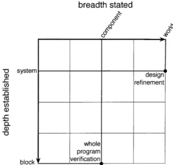
An argument's breadth, is the granularity of the stated goal, while its depth is the granularity into which it recasts that goal. For example, a system refinement argument might state a claim about the system architecture as a whole and recast
narrow broad
tated'
established
argument
Figure 2-2: An argument states a property at a certain breadth and establishes it. by examining the system at a certain depth.
that claim into a set of assumptions about the components of the system. As we will see later, a collection of arguments can be strung together to build a composite argument with greater breadth (further to the right) and greater depth (further down) than any one of the components.
x-axis: The x-axis position of an argument is its breadth. The narrowest (left-most)
arguments deal with goals stated about code blocks, such as assertions and invariants. The broadest arguments deal with goals stated about the context in
which the system operates, such as safety requirements imposed by regulatory
agencies.
y-axis: The y-axis position of an argument is its depth. The shallowest arguments
are established at the world granularity, looking at the interactions between the system and its stakeholders, but without considering the architecture of the
system. The deepest arguments are established at the code block granularity, looking at the full semantics of the software.
statements: An <x, x> point on the main diagonal is a statement about the
granularity x. A <system, system> point is a statement about the system
- a requirement. A <component, component> point is a statement about a
component of the system - a domain assumption.
arguments: An <x, y> point below the main diagonal is an a'rgulment that the statement at <y, y> holds as long as a certain set of statements at <x. x> hold. For example, <system. component> is an argument that a system requirement is enforced by a set of component assumptions.
0 CD O 0) com a CUU)CE 0 ,
stated as property on...
CI 0 context system Iponen-arguments module block , IIa
Figure 2-3: Points on the main diagonal represent statements about the system at a particular granularity. Points below the main diagonal represent arguments that establish one statement based on a set of statements (assumptions) at a lower granularity.
invalid points: The upper-lefthand triangle of the diagram is empty breadth is always greater than or equal to depth. A property cannot be established at a higher granularity than it is stated. For example, one cannot show that a component obeys its specification by noting that the system has a certain requirement, whereas one can do the reverse - argue that a system has a requirement because a component obeys its specification.
2.1.3
Sample Arguments
Consider two particular points in this diagram: design refinement, at <world, system>, and whole program verification, at <component, block>.
Arguments at <world, system> are design refinement arguments; they recast
claims/goals stated about the world surrounding the system into claims/goals stated about the system under analysis (treated as a black box) and claims/goals stated about other systems interacting with the system under analysis.
For example, a high level hazard analysis for a chemical tank would be a design
regfinerment argument. It recasts safety constraints (that the tank does not harm
surrounding equipment) into constraints about the chemical tank (that it does
breadth stated -0 system (D design .- refinement Co .4 c, c-0 V1 block
Figure 2-4: The breadth and depth of two sample argument styles.
not vent more than X grams of corrosive gas per day) and constraints about the surrounding equipment (that they will not be damaged by exposure to X grams
of corrosive gas per day). A world goal (damage to surrounding assets) has been
decomposed into system goals (how many grams of gas can be vented per day). In contrast, at < component, block> we have whole program veri7fication arguments, which recast goals about an entire software component and establish them in terms of the semantic of individual block of code.
For example, a thorough manual review of the software that controls a chemical valve would be whole program verification. It would take a property stated about the system as a whole, that it correctly send signals to the value according to a prescribed pattern, and recasts it as properties about the semantics of the language used (e.g. that the send_opensignal does indeed send an open signal to the value, and that a wait_l_second really does pause for 1 second). Of course, manual exhaustive review might be too costly or too error prone to be suitable for a particular analysis, but it certainly fits the mould of a whole program verification argument.
whole program
stated as property on...
ell
(9
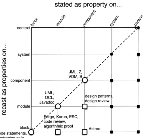
JML, Z, " VDM, B 0 U)CnUML, .z OCL, design Javadoc design O module .v.drge, arun, ESC, /code re iew,
block / algorith ic proof Astre
code statements, abstracted calls pattern, review e e /S.
Figure 2-5: Program Analysis (PA) techniques reside in the lower lefthand region, providing depth but not much breadth.
2.1.4
Existing Techniques
CDADs do not directly represent the cost (both human and computational) of building the different kinds of arguments, although we discuss extensions of the CDAD notation to express such information in Chapter 7. In general, moving deeper (down) and broader (right) raises cost and/or lowers confidence.
The fields of program analysis (PA), requirements engineering (RE), and testing are represented by clusters of argument types in the CDAD.
PA: Program analysis techniques (PA) occupy the lower-left-hand region, as shown in
Figure 2.1.3 -- the properties are stated and established at a low granularity. PA techniques rarely address properties stated at or above the system granularity, as such properties are too broadly stated to be amenable to automatic analysis. We
context i 0 (D C) 1 - - L- - - 9- --sysemI I
I41VI-stated as property
on...
oS-STAIP diagram,,
custor er intervipfi
DFDs, OPM,
/
pro lem diagram, ,
O system use cases
. - hazard analy s,
Q- J4 aper prototypi g
CL state charts f
O component
. , fault trees, KAOS
0 event trees,v C/ MEA, FMECA CO 0 module 0) blockl,/
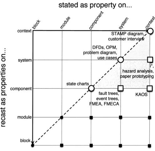
Figure 2-6: Requirements Engineering (RE) techniques reside in the top right corner, with great breadth but limited depth.
indicate this obstacle with the vertical system complexity barrier in Figure 2.1.3.
RE: Requirements engineering techniques (RE) occupy the upper-right-hand region,
as shown in Figure refcdad-RE - the properties are stated and established at a high granularity. RE techniques rarely establish properties below the system gTanularity, as doing so produces descriptions that are too large and complex to be reasoned about. We indicate this obstacle with the horizontal component
complexity barrier in Figure 2.1.3.
Testing: Testing techniques occupy the bottom row; they provide deep analysis at various breadths, as shown in Figure 2.1.3. Testing can provide the breadth of RE and the depth of PA, but fundamentally cannot provide the confidence needed to build a dependability argument. Testing assures that the system operates correctly in the tested scenarios, but provides no guarantees about scenarios not specifically tested.
narrow ( > broad component complexity barrier system ,complexity barrier __________________ __________________
__________________
Figure 2-7: Requirements engineering techniques tend to stay above the component
complexity barrier, to avoid introducing too much detail about the operation of the underlying system. Program analysis techniques tend to stay left of the system complexty barrier, to avoid introducing the details of too many interacting components of the system.
technique at the lower-right-hand-most corner - one that states a property at the highest (world) granularity and establishes it at the lowest (block) granularity. Unfortunately. getting anywhere near that goal requires crossing both complexity barriers.
2.1.5
Dependability Arguments
Most tasks do not require the holy grail and can make do with more modest approaches. For example, verifying that libraries obey their contracts requires only a <module, block> style argument, and can be established using program analysis techniques such as Greg Dennis's Forge [23] or Patrick Lam's HOB [46]. Similarly, determining if a given software specification is sufficient to enforce a given system requirement requires only <system, comrponernt> or better, and can thus be satisfied by requirement progression [81]. However, the important class of end-to-end dependability arguments lies outside the ranges of conventional PA and RE techniques.
stated as
0
contextC-0 system CO a) I-CD CL L component CL U) 4--U) block
property on...
)
cLo /d regression ests, usability testing,
-, full compo ent tests integration testing
unit tests deployment testing
Figure 2-8: Testing techniques reside on the bottom row, establishing properties at the depest level and a variety of breadths. However, testing alone does not provide the confidence needed for a dependability argument.
at the system granularity (or higher) and establish those properties at the module granularity (or lower). For example, part of the BPTC dependability argument (described in Chapter 4) is to establish that patients do not receive more radiation than their prescriptions indicate. Such an argument should be grounded in the code, so that if the requirement is changed (e.g. to say that the patient cannot receive less than their prescription either) or if the system is changed (e.g. to include an additional firing mode), one can determine which parts of the code need updating, if any.
Figure 2.1.4 shows the space of solutions that. are appropriate for building this kind of dependability argument. While we do not necessarily need to achieve the
stated as property on...
2 component
0 module
Figure 2-9: Neither requirements engineering (top right) nor program analysis (bottom left) techniques have enough breadth and depth to reach the lower right area, where dependability arguments reside. However, composition of RE and PA techniques can get us there.
bottom-right corner to build dependability arguments, we do need something more than we have - neither PA nor RE techniques have sufficient breadth and depth to
land in the target region. We can, however, compose existing PA and RE techniques, together with some additional work, to create a composite technique that falls within the target region, as shown in Figure 2.1.4. The challenge of building composite techniques is to keep the cost from rising too high without letting the confidence drop too low.
2.1.6
Composition
Building composite arguments take more than picking two techniques that, between them, have sufficient breadth and depth.
(a) The techniques must match up.
We can't reach the bottom right corner (<world, block>) with just hazard analysis (<context, system>) and a code review (<module, block>). While those arguments have sufficient breadth and depth between them, they do not
stated as property on... a"~B~g O system CL O component oz module 0
Figure 2-10: A composite argument built out of smaller arguments can reach the bottom right position (max breadth, max depth), even when no individual technique can reach that point.
connect together. An additional argument is needed to connect the system statements used to establish the hazard analysis with the module statements established by the code review.
(b) There needs to be glue between the techniques.
We can't reach <system, block> with just KAOS [21, 22, 18, 8] (<system,
component>) and Astree [9, 10] (<component, block>). The claims generated by KAOS are at the right level to be established by an Astree analysis, but
they may not be in the right form. In order to connect up the two arguments, a glue argument may be needed - an argument that actually rests on the main diagonal, and serves only to rephrase a statement within the same granularity. In this case, we need glue at <component, component>) to recast the claims generated by KAOS into claims that can be established by the Astree.
(c) The component techniques must provide sufficient confidence and coverage at
acceptable cost.
We could reach the bottom right corner (< world, block>) using just deployment
testing (<world, block>), but doing so will not provide sufficient confidence.
While it has sufficient breadth and depth, testing the entire system on real patients and observing the results does not give us the confidence needed to certify the system as dependable. Testing fundamentally cannot provide the level of coverage needed to certify a complex system with confidence. We discuss ways to add confidence and cost information to CDADs as future work, in
stated as property on...
0 U)a)
,
0L 0 U)Cz
4--j U) 0a,
-1 component2.2
Structuring a Dependability Argument
Our general approach to constructing composite arguments can be applied to the BPTC case study by instantiating it with a particular set of component techniques. Figure 2.1.6 shows the techniques we combine, as arguments and statements, to form the composite technique we use in Chapter 4.
Hospital Needs : An informal discussion with hospital administrators about the
role of the BPTC at MGH.
This statement is at <context, context>.
Hazard Analysis : A characterization of dangerous states that could be induced
by the system, including a classification of each hazard's danger level (low, medium, high) [49].
This argument is at <context, system>.
Designations : A list of formal terms, both domains and phenomena, which will
be relevant to the argument. Each term is mapped to an informal description, serving to ground our formality in the real world.
This statement is at <system, system>.
Problem Diagram : The system requirement is initially expressed with a problem
diagram, from the Problem Frames approach [40, 38]. This step recasts the requirement from its original (possibly informal) statement into a form that is
be amenable to requirement progression. It identifies the domains relevant to
the subsystem under consideration, and the phenomena through which those domains interact, using the formal terms introduced by the designations.
This statement is at <system. systerr>.
Requirement Progression : The system requirement is transformed into a software specification using requirement progression [81]. The resulting diagram
is called an argument diagram, which is the problem diagram annotated with a
collection of domain assumptions (breadcrumbs) sufficient to enforce the original system requirement. Domain assumptions about software components can be used as specifications for those components.
This argument is at <system, component>.
Argument Validation : Along with the argument diagram is an Alloy [30] model
which mechanically confirms that the breadcrumbs do indeed enforce the desired system property.
Breadcrumb Assumption Interpretation : The domain properties inferred by
Requirement Progression are interpreted back into the languages of their domains, using the designations, and decomposed into component assumptions about its domain. Each component assumption is classified as software correctness (c). software separability (s), or non-software properties (x). The decomposed assumptions are now amenable to domain specific analysis.
This statement is at <component, component>.
Phenomenon Assumption Interpretation : Problem diagrams contain implicit
assumptions, such as atomicity and inter-domain consistency. These assumptions are also interpreted, decomposed, and classified as (c), (s), or
This argument is at <component. component>.
Specification for TM : A specification of the correct behavior of the Treatment
manager, resulting from interpreting one of the breadcrumbs derived during requirement progression. It is now phrased in terms of code terminology, and is thus amenable to analysis.
This statement is at <component, component>.
Trace Extraction : The process of identifying the subset of the code relevant to
the TM specification. It is identifying by using a Flow Diagram, an informal annotation of the problem diagram, indicating the flow of information through the system. The flow diagram is used to label (and thus implicitly order) the domains and the letters assigned to arcs. These labels are purely for the sake of bookkeeping and help us to systematically develop the argument.
This argument is at <component, module>.
Specification for Trace : A specification of what it means for the identified subset
to be correct. In this case, it is the same claim as the specification for the treatment manager, but now applied to a small chunk of code.
This statement is at <module, module>.
Forge Analysis : The individual pieces are discharged using existing analysis
techniques. Separability assumptions are addressed with impact analysis, and correctness properties are addressed using a combination of manual inspection and automatic analysis via the Forge framework.
This argument is at <module, block>.
Code Statements : Individual lines of code in the code base, and the assumption
that they have the semantics assigned to them by Forge. This statement is at <block, block>.
Together, these component techniques provide an argument at <context, block>, well within our the zone for Dependability Arguments. The component techniques provide sufficient confidence to allow the overall argument to be used to certify the
Chapter 3
Requirement Progression
3.1
Overall Approach
The pr'oblem frames approach offers a framework for describing the interactions amongst software and other system components [38, 40]. It helps the developer understand the context in which the software problem resides, and which of its aspects are relevant to the design of a solution [31, 39, 44 7]. In this approach, a requirement is an end-to-end constraint on phenomena from the problem world, which are not necessarily controlled or observed by the machine. During subsequent development, the requirement is typically factored into a specification (of a machine to be implemented) and a set of domain assumptions (about the behavior of physical devices and operators that interact directly or indirectly with the machine).
3.1.1
The Need for Progression
A key advantage of the problem frames approach is that it makes explicit the argument that connects these elements. In general, this argument takes a simple form: That the specification of the machine, in combination with the properties of the enviromnent, establishes the desired requirement. When the environment comprises multiple domains, however, the argument may take a more complicated form. The problem frames representation allows the argument to be shown in an
argmet diagrarm the problem diagram embellished with the argument.
In the problem frames book [40], a strategy for constructing such arguments, called problem progression, is described. But, since each step in a problem progression
involves deletion of domains from the diagram, the strategy does not result in an argument diagram; rather, it produces a series of diagram fragments. The approach described in this paper, which we call requirement progressiorn, likewise aims to produce an argument diagram. Its steps produce accretions to the diagram, never deletions, and the diagram resulting from the final step is an argument diagram in the expected form.
Often, the problem diagram fits a well established pattern (a problem frame), and the argument required will be an instantiation of an archetypal argument. As our logging example will illustrate, not all problems match existing frames, and an argument diagram must be specially constructed using progression.
3.1.2
Our Approach
Our approach relies upon the analyst's ability to accurately distill, disambiguate, and formalize the requirement. One of the benefits of problem oriented software engineering [44], of which problem frames is an example, is that the analyst is permitted to formulate the requirement in terms of whatever phenomena are convenient for describing the actual system requirement. For example, a designer of a traffic light might write a requirement saying "cars going different directions are never in the intersection at the same time". The analyst then methodically transforms the requirement so that it constrains only controllable phenomena, making sure that the new version is sufficiently strong to enforce the original requirement. For example, the traffic light designer might reformulate the requirement to say "the control unit sends signals to the traffic lights in the following pattern...", and justify the reformulation by appealing to known properties about how cars and traffic lights behave. Attempting to write the reformulated version froln scratch is error prone. As with other progression techniques (e.g. [70]), our goal is to provide support for performing that transformation systematically and accurately. Our technique is most
appropriate when the requirement can be phrased in a formal language, although the methods we describe could also guide reasoning about informal requirements.
We demonstrate our technique on two examples. The first example is of a two-way traffic light similar to the one described in the problem frames book [40]. It demonstrates the use of our technique to specialize the correctness argument of the problem frame that matches the problem diagram. The second example is a simplified view of the logging facility used in a radiation therapy medical system. It demonstrates the use of our technique when no single existing problem frame matches the entire problem. These examples are perhaps not sufficiently complex to properly demonstrate the need for systematic requirement progression, but they do illustrate the key elements of our approach and indicate its strong and weak points.
In both examples, the various constraints are formalized in the Alloy modeling language, and the Alloy Analyzer [30. 34. 37] is used to check that the resulting specification and domain assumptions do indeed establish the desired system-level properties. The Alloy Analyzer can check the validity of a transformation with a bounded, exhaustive analysis. Our transformation technique is not tied to Alloy; we chose Alloy because it is simple, was familiar to us, provides automatic analysis, and allows a fairly natural expression of the kinds of requirements and assumptions involved in these examples.
In Chapters 4 and 5 we apply requirement progression to reals systems, demonstrating its applicability to complex system. There, we see that these techniques scale to reals systems, and are not actually much more difficult to use there than on the toy examples shown in this chapter.
3.2
Problem Frames
Before one can establish a system requirement, one must articulate it.
The Problem Frames approach is a technique for describing and analyzing desired system properties. The Problem Frames approach offers a framework for describing the interactions amongst software and other system components [38, 40]. It helps the
developer understand the context in which the software problem resides, and which of its aspects are relevant to the design of a solution [31, 39, 47]. Once the requirement is articulated as a problem diagram, it becomes amenable to more systematic analysis (Section 3.3).
The problem frames approach is an example of problem oriented software
engineering [44], meaning that it focuses on the context in which a system operates
rather than the internal architecture of the system. It emphasizes the distinction between phenomena one wishes to indirectly constrain (the system requirement) and phenomena the software can directly control (the component specifications and domain assumptions). System analysis is a matter of understanding the indirect links between those two sets of phenomena.
One benefit of this approach is that the analyst formulates the system requirement in terms of whatever phenomena are most appropriate and convenient. As a result, we have a higher confidence that the written requirements accurately reflect the intended requirements. Attempting to directly write the requirement in terms of controllable phenomena can be subtle and error prone. The problem frames approach separates the articulation of the requirement from the transformation of that requirement into a form usable as a specification.
In this chapter, we will describe Requirement Progression, a technique for systematically decomposing a system requirement (written in terms of the phenomena to be controlled) into a set of specifications (written in terms of controllable phenomena). First. however, we will examine Problem Frames in a bit more detail.
3.2.1
More Detail
An analyst has. in hand or in mind, an end-to-end requirement on the world that some machine is to enforce. In order to implement or verify the nachine, one needs a specification at the machine's interface. Since the requirement typically references phenomena not shared by the machine, it cannot serve as a specification. The Problem
Frame notation expresses this disconnect as shown in Figure 3-1. 1
ITchin
phenomena interface Problem World _ phenomena referenced - Requremen-RequemFigure 3-1: A generic problem frames description showing the disconnect between the phenomena controlled by the machine (the interface phenomena) and those
constrained by the requirement (the referenced phenomena).
The analyst has written a requirement (right) describing a desired end-to-end constraint on the problem world (center). The requirement references some subset of the phenomena from the problem world (right arc). A machine (left) is to enforce that requirement by interacting with the problem world via interface phenomena (left arc).
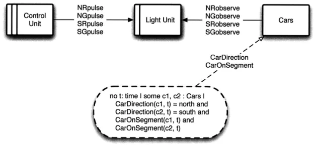
For example, in a traffic light system, the problem world might consist of the physical apparatus (lights and sensors) and external components (cars and drivers), the requirement might be that cars do not collide, and the specification would be the protocol by which the machine generates control signals in response to the monitoring signals it receives. Tile machine and its specification only have access to the phenomena pertaining to control and feedback signals, whereas the requirement is a constraint on the directions and positions of the cars.
The problem world is broken into multiple domains, each with its own assumptions. Here, for example, there may be one domain for the cars and drivers (whose assumptions include drivers obeying traffic laws), and another for the physical control apparatus (whose assumptions describe the reaction of the lights to control signals received, and the relationship between car behavior and monitoring signals generated). A problem diagram shows the structure of the domains and phenomena involved in a particular situation. One possible problem diagram for the traffic light
1We deviate slightly from the standard problem frames notation when drawing an arc indicating that domain D controls phenomenon p. Rather than labeling the arc D! p, we label it p and place an arrow head pointing away from D. When not all phenomena shared by two domains are controlled by the same domain, separate arcs are used. Most of our diagrams omit indications of control altogether, as it is not currently relevant to our approach.
system is shown in Figure 3-2.
observ Cars and location
signals ations Drivers position NoCollisions
Figure 3-2: A problem diagram describing the domains and phenomena for a two-way traffic light. The arc connecting two domains is labeled by the phenomena shared by those domains - those phenomena that both domains involve. The arc connecting
the requirement to a domain is labeled by the phenomen referenced (constrained) by the requirement.
To ensure that the system will indeed enforce the requirement, it is not sufficient to verify that the machine satisfies its specification. In addition, the developer must show that the combination of the specification and assumptions about the problem world imply the requirement. To argue that the machine, when obeying the specification, will enforce the requirement, we must appeal to assumptions about how the domains act and interact - how lights respond to control signals, how monitoring signals are
generated, how drivers react to lights, and how cars respond to driver reactions. Those behaviors are recorded as domain assumptions, as shown in Figure 3-3.
observ- Cars and location<No Coision
Controller signals ghts ations Drivers position
sigrnals observations
signals observations location
position
Assumption Assumption
Figure 3-3: Assumptions about the intervening domains are expressed as partial domain descriptions in the form of constraints on their behaviors. These assumptions help us relate the machine specification to the system requirement. As with a requirement, the arc connecting an assumption or specification to its domain is labeled with the phenomena referenced by that assumption.
A problem diagram serves to structure the domains and their relationships to the machine and the requirement, and is accompanied by a frame concern that structures
the argument behind this implication. The traffic light system, for example, matches the required behavior shown in Figure 3-4 [40].
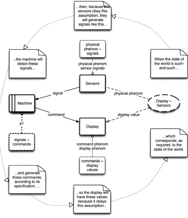
commands commands Specification on commands The Machine generates commands according to the Specification, so...
Device - - - behaviors - - - Requirement !on behaviors
commands behaviors
commands
-...because the
Device exhibits ...the Requirement behaviors based on on behaviors will
commands like hold..
this...
Figure 3-4: An informal argument diagram for the required behavior frame.
Because the required behavior frame concern is general enough to match many situations, it only gives an outline of the correctness argument and serves primarily to focus attention on the kinds of domain properties upon which the completed correctness argument is likely to rely. Applying it to the traffic light problem diagram suggests the argument structure shown in Figure 3-12.
This information is a valuable aid in building the full argument, but would greatly benefit from a systematic approach for determining exactly which properties of the domains are relevant, deriving an appropriate specification for the machine, and providing a guarantee that the specification and domain properties are sufficient to establish the requirement. This chapter describes such an approach.
Controller signals Lights obse Cars and location / Collisions
ations Drivers position
signals observations
signals observations location
position
Specification I Lights Cars
onsignals i Assumption Assumption
The Controller ...the requirement on
ontrols the signal ...because the ...and because light
puolstes according to signal pulses relate observations relate car locations and
pulses according to to light observations to car locations and positions will hold,
this Specification, like this... positions like this... preventing cars from
so... colliding.
Figure 3-5: The informal argument diagram that results from applying the required behavior frame to the two-way traffic light problem diagram. It provides an outline for arguing that the specification enforces the requirement, and it indicates what sort of domain assumptions will be needed to build that argument.
3.3
Requirement Progression
In this section, we introduce an incremental way of deriving a specification from a requirement via requirement progression. A byproduct of the progression is a trail of domain assumptions, called breadcrumbs, that justify the progression and record the line of reasoning that lead to the specification.
Requirements, specifications, and breadcrumbs are three instances of domain
constraints. Requirements can touch any set of domains but usually touch only
non-machine domains; specifications touch only the machine domain; and each breadcrumb touches only a single non-machine domain. The only thing barring the requirement from serving as a specification is that it mentions the wrong set of phenomena. Unfortunately, altering it to mention the right set of phenomena (those at the interface of the machine domain) is no easy matter and requires appealing to properties of the intervening domains. The transformation process we describe is