HAL Id: hal-02509624
https://hal.laas.fr/hal-02509624
Submitted on 9 Nov 2020
HAL is a multi-disciplinary open access
archive for the deposit and dissemination of
sci-entific research documents, whether they are
pub-lished or not. The documents may come from
teaching and research institutions in France or
abroad, or from public or private research centers.
L’archive ouverte pluridisciplinaire HAL, est
destinée au dépôt et à la diffusion de documents
scientifiques de niveau recherche, publiés ou non,
émanant des établissements d’enseignement et de
recherche français ou étrangers, des laboratoires
publics ou privés.
Frequency doubling in cavity-resonator integrated
grating filter
Francois Renaud, Olivier Gauthier-Lafaye, Antoine Monmayrant, Evgeni
Popov, Anne-Laure Fehrembach, Stéphane Calvez
To cite this version:
Francois Renaud, Olivier Gauthier-Lafaye, Antoine Monmayrant, Evgeni Popov, Anne-Laure
Fehrem-bach, et al..
Frequency doubling in cavity-resonator integrated grating filter.
High
Con-trast Metastructures IX (SPIE OPTO, 2020), Feb 2020, San Francisco, United States.
pp.11,
�10.1117/12.2542771�. �hal-02509624�
Frequency doubling in Cavity-Resonator Integrated Grating
Filter
F. Renaud
a,b, O. Gauthier-Lafaye
b, A. Monmayrant
b, E. Popov
a, A.-L. Fehrembach
a, S. Calvez*
bS. Gregory Jones*
a, Titania A. R. Schmidt
b, Kenneth M. Suzuki
aa
Aix Marseille Univ, CNRS, Centrale Marseille, Institut Fresnel, F-13013 Marseille, France
b
LAAS-CNRS, Université de Toulouse, CNRS, 7 avenue du colonel Roche, F-31400 Toulouse,
France
ABSTRACT
Guided Mode Resonant Filters (GMRFs) have long been studied as a support surface for nonlinear optical interactions due to their intrinsically high Q-factor. However, their operation relies on a non-localized and large-area guided mode that limits the achievable power density and requires complex phase-matching approaches. Conversely, photonic crystal nano-cavities have shown promising results due to both their high-Q factors to enhance the pump field and their localized nature that allows phase-matching-free implementation and high power density excitation. However, their intrinsic small size restricts the supported input power and hinders the coupling efficiency of the pump into the mode. In this paper, we report the first experimental demonstration of continuous-wave second harmonic generation in a Cavity-Resonator Integrated Grating Filter (CRIGF). This intermediary device, which can be described as a cavity-enhanced finite-size GMRF or, equivalently, as a low-index-contrast photonic crystal micro-cavity, will be shown to offer a practical route to nonlinear interactions with viable power (<20 mW) and excitation conditions (surface excitation with a ~10-µm-waist spot size). In practice, the devices under study make use of a lithium-niobate on insulator (LNOI) waveguide with a nanostructured silicon nitride upper cladding as a pragmatic way to implement a high second-order nonlinearity platform with established processing technology. The already-demonstrated versatility of the CRIGF design (demonstrated at wavelengths of 850 nm using S3iN4/SiO2 platform, 4.5 µm with the GaAs/AlGaAs technology and,
here, at 1.55 µm with the LiNbO3 platform) coupled to the electro-optical tuning afforded by lithium niobate system
makes this approach extremely promising for pixelated non-linear systems.
Keywords: second harmonic generation, guided-mode resonance filters, lithium niobate, cavity-resonant integrated
grating filter, nonlinear frequency conversion
1. INTRODUCTION
Guided Mode Resonant Filters (GMRFs) have been studied as devices for nonlinear optical interactions due to their intrinsically high Q-factor 1,2. Given that their principle is based on non-localized and large-area guided mode(s), to ensure an efficient nonlinear conversion, the excitation beam needs to have a low-divergence and be wide and thereby the operation is inherently limited by the achievable power density. Furthermore, to achieve the constructive harmonic generation over such large surfaces, the phase-matching condition has to be strictly met. Conversely, photonic crystal nano-cavities have shown promising results due to both their high-Q factors to enhance the pump field and their localized nature that allows phase-matching-free implementation and high power density excitation 3,4. However, their intrinsic small size restricts the supported input power and hinders the coupling efficiency of the pump into the mode. In this paper, we report the first experimental demonstration of continuous-wave second harmonic generation (SHG) in a low-index-contrast photonic crystal micro-cavity or equivalently in cavity-enhanced finite-size GMRF that is also known as a Cavity-Resonant Integrated Grating Filter (CRIGF) 5,6. Practically, the device was made using a hybrid lithium niobate and silicon-oxynitride technology.
2. DESIGN
As shown on Figure 1, the considered CRIGF structure relies on a lithium-niobate-on-insulator (LNOI) substrate since this technological platform combines a high non-linear susceptibility (of 33pm/V) with an ability to make high-confinement but low-loss waveguides 7–9. Here, the sample consists of a 297-nm-thick X-cut lithium-niobate core on a 2µm-thick SiO2-coated lithium-niobate substrate of similar orientation.
We chose to use two additional layers (made of Si3N4 and SiO2) to form the upper-cladding of the waveguide such that
we could create an anti-reflective multilayer stack at the fundamental wavelength of design (1555 nm) under surface-normal excitation and choose the bandwidth of the Distributed Bragg Reflectors that sets the micro-cavity. From these thicknesses, we defined the coupling grating and DBR constitutive parameters based on standard effective index calculation of the TE-polarized mode and set the phase section length to obtain a resonance at the design wavelength. The resulting parameters are listed in Table 1 and Figure 1. Further details on the design procedure can be found in 10.
Figure 1. Schematic of the CRIGF structure under study
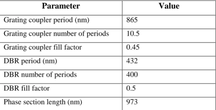
Table 1. Parameters of the CRIGF nano-structured elements.
Parameter
Value
Grating coupler period (nm) 865
Grating coupler number of periods 10.5
Grating coupler fill factor 0.45
DBR period (nm) 432
DBR number of periods 400
DBR fill factor 0.5
Using RCWA calculations and assuming a mode-matched excitation and a loss-less waveguide, the CRIGF is shown to have a ~1 nm bandwidth with a maximum reflectivity of 85.3% and minimum transmission of 14.7% (see Figure 2). The generated second harmonic signal was also calculated under the undepleted pump approximation and is shown on Figure 2 to be exalted at the device resonance. Further information on the calculations are available in reference 11 together with a comparison to the expected results from substrate-only and GMRF-based generation.
Figure 2. Calculated spectral reflectivity (black) and transmission (grey) of the designed CRIGF.
To complement this information, we also computed the substrate-radiating SHG pattern presented in Figure 3 by selecting the modal content whose wavevectors are above the light cone. The SHG emission diagram exhibits three peaks that can be assigned to the extraction of the SHG signal by the grating-coupler section (through the 0th and ±1st orders).
3. FABRICATION
The device fabrication started from the LNOI planar waveguide described above obtained from NanoLN. The first layer of the waveguide upper-cladding layer, made of Si3N4, was deposited using an Inductive-Coupled-Plasma
Plasma-Enhanced Chemical Vapor Deposition system. The designed gratings were subsequently patterned into this layer using nano-imprint lithography 12 and dry etching with the LiNbO3 top surface acting as an etch-stop interface. The device
fabrication was completed by the deposition of a 323-nm-thick SiO2 upper cladding layer on top of the grating structure
and of a 266-nm-thick SiO2 single-layer anti-reflective coating on the rear-side of the substrate to avoid back-reflection.
4. CHARACTERISATION
The sample was characterized using the setup shown in Figure 4. The tunable source delivered up to 17 mW of fundamental signal at a wavelength tunable from 1500 to 1630 nm with a linewidth of ~100 kHz and was optically relayed using a telescope system to ensure mode-matched excitation of the CRIGF. The generated second harmonic signal was collected using a NA=0.15 lens, separated from the pump using a dichroic filter and analyzed using a visible spectrum analyzer. In the absence of an InGaAs camera, the 980nm beam served as a guide to align the 1550 nm beam and was turned off during the measurements.
DAQ 1550nm Tunable laser 10% 90% XYZ ISO CMOS camera LED 50 /5 0 WDM XYZ Sample XYZ WDM UV-VIS OSA
Figure 4. Setup used for that characterisation of the considered CRIGF.
As shown in Figure 5, the second harmonic signal is observed to increase significantly at a wavelength of 1555 nm corresponding to the device resonance. We were also able to establish that a fraction of the SHG signal is also diffracted at ~±60°, in agreement with the above-displayed calculated radiation pattern.
Figure 5. CRIGF SHG spectral characteristic reccorded at normal incidence.
Polarization analysis reveals that the second harmonic emission is TE-polarized as expected and accounted for in the numerical simulations.
Figure 6. Measurement of the SHG polarisation state (a=0° for analysis polarizer along the grating lines).
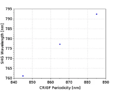
Finally, the measurement of the performance on three devices with scaled designs (corresponding grating coupler periods of 845, 865 and 885 nm) enabled to demonstrate the linear dependence of the SHG wavelength to the device design parameter (or equivalently resonant wavelength), consistent with cavity-enhanced SHG operation.
Figure 7. SHG tunability with CRIGF design parameter (here taken to be the grating coupler period).
5. CONCLUSION
We demonstrated successful continuous-wave SHG enhancement in CRIGF structures made using a hybrid lithium-niobate/silicon oxynitride technology. Future prospects will be to look for improved nonlinear conversion performance using a combination of optimised SHG-CRIGF designs and improved fabrication processes.
ACKNOWLEDGEMENTS
The authors would like to thank NanoLN for providing the LNOI sample onto which the device was fabricated and acknowledge that part of the work was funded by the ANR ASTRID “RESON” and also the technical support from the LAAS-CNRS micro and nanotechnologies platform, member of the French RENATECH of cleanroom facilities.