HAL Id: hal-02155033
https://hal.archives-ouvertes.fr/hal-02155033
Submitted on 13 Jun 2019HAL is a multi-disciplinary open access
archive for the deposit and dissemination of sci-entific research documents, whether they are pub-lished or not. The documents may come from teaching and research institutions in France or abroad, or from public or private research centers.
L’archive ouverte pluridisciplinaire HAL, est destinée au dépôt et à la diffusion de documents scientifiques de niveau recherche, publiés ou non, émanant des établissements d’enseignement et de recherche français ou étrangers, des laboratoires publics ou privés.
Assessment method of masonry arch bridges
Nathalie Domede, Alain Sellier
To cite this version:
Nathalie Domede, Alain Sellier. Assessment method of masonry arch bridges. Structural Faults and Repair, Jun 2008, EDIMBOURG, United Kingdom. �hal-02155033�
Assessment method of masonry arch bridges
Nathalie Domède, INSA de Toulouse, LMDC, 135 avenue de Rangueil, 31077 TOULOUSE CEDEX 4, France, nathalie.domede@insa-toulouse.fr
Alain Sellier, Université Paul Sabatier, LMDC, 135 avenue de Rangueil, 31077 TOULOUSE CEDEX 4, France, alain.sellier@insa-toulouse.fr
KEYWORDS: masonry, arch bridges, brick, lime mortar, interface element.
Abstract
The aim of the research presented here was to build an assessment method for masonry arch bridges by modelling and computing. The method was developed on a masonry vault build in 1870 in south-west of France with bricks, stones and hydraulic lime. The first step was an historic research in order to know the bridge constitution. The second step was an
experimental approach whose aim was to establish the homogenized masonries mechanic behaviour law and an interface law between homogenized blocks. The interface law used “joint elements” including the mortar crack in tensile and shear behaviour. The third step was the 3D computing of the bridge, using a finite element method. Several boundary conditions were explored, blocked or slipping support, to describe the arch bridge behaviour.
Introduction
The study presented here was done in association with RFF-SNCF (Réseau Ferré de France – Société Nationale des Chemins de Fer), the French railway corporation. 44% of the bridges used by railway lines are masonry bridges. They were built between 1840 and 1920. They are more or less damaged but it is necessary to let them open to traffic and to adapt them to traffic. Conservation is not sufficient. RFF-SNCF needs to know if the bridges can support the
current and further traffic: it is an assessment and requalification problem. In this research, our aim was to find a new approach of masonry arches assessment.
At first, we have chosen a bridge to test our method. A historical search was necessary in order to obtain as much information as possible about the bridge (material geometry,
boundary conditions). Secondly, an experimental research was developed in order to find the mechanical laws governing the behaviour of the 4 masonries composing the bridge. At the end, we developed a numerical 3D model using the finite element method. By a 3D model, we wanted to show the transverse effects, already studied by Boothby (2001).
Comparative studies realised previously (Giordano et al., 2002), decided us to select a FEM method. Our bridge model proposes a simultaneous use of complementary massive finite elements and joint elements. Macro-elements describe homogenized behaviour of masonry in linear and non linear domain up to the compressive strength, while joint elements model the capacity of materials to crack under tension and shear.
The studied bridge
The study concerned a bridge of a railway line built in 1870 by the Compagnie des Chemins de Fer du Midi in South-west France, between Castelnaudary and Albi (Tarn). The plans and written documents we found in SNCF files yielded precise information on the twenty
masonry vaults of the line. They all use the same masonries and same materials, made near the worksite. The similarities between the bridges give a regional character to these structures.
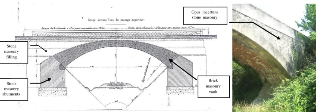
We chose the bridge described in figure 1 and 2. It is composed of a vault in brick masonry, wall ties in calcareous stone masonry, spandrel walls in opus incertum stone masonry, and filling in rubble stone masonry. All the mortar joints are made of hydraulic lime mortar without any cement.
It has superficial foundations made of lime concrete.
Stone masonry abutments Brick masonry vault Stone masonry filling Opus incertum stone masonry Stone masonry abutments Brick masonry vault Stone masonry filling Opus incertum stone masonry Stone masonry abutments Brick masonry vault Stone masonry filling Opus incertum stone masonry Stone masonry abutments Brick masonry vault Stone masonry filling Opus incertum stone masonry
Fig. 1 - General view of the masonry arch studied (SNCF / RFF, 1870). Length: 14.37m, key vault thick: 79cm, radius: 10.75m, width: 4.80m.
Stone masonry Brick masonry vault Stone masonry Brick masonry vault Stone masonry Brick masonry vault Stone masonry Brick masonry vault
Constitutive law for masonries
The bridge is made of four different masonries. We determined a mechanical behaviour law for each of them. A bibliographical study revealed that the data concerning the old materials were not sufficient, in particular for regional materials such as the bricks used in the south-west of France and the stones extracted from small quarries that are no longer exploited (only one recent paper was found about hydraulic lime mortar, written by Lanas, 2004). It was therefore necessary to carry out an experimental study to determine first the behaviour of the basic materials (brick, lime mortar and calcareous stone), and then, the behaviour of whole masonries.
Because we where not allowed to take off the bridge some specimen, the experimental tests were realised on new mortar. SOCLI NHL 3.5 lime was selected because it is a hydraulic lime without any additives. It is produced in the Pyrenees and is similar to the hydraulic lime used to build bridges in south-west France during the 19th century. It is made up of lime Ca(OH)
2,
calcite CaCO3 and silicate C2S.
lime Ca(OH)2 Calcite CaCO3 Silicates C2S Quartz Water 17.6 30.4 40.5 9.5 2
Tab. 1 - Mineralogical composition of SOCLI NHL 3.5 lime (percentages).
An accelerated carbonation was applied to the lime mortar in order to determine the relationship between young and old mortar behaviour.
The bricks used were made by the “Terres cuites de Savès” Company, an establishment near Toulouse. They were hand-made moulded solid bricks without perforations, as it was done in the second half of the 19th century. Their dimensions were 37 cm * 24 cm * 5 cm (Fig. 3).
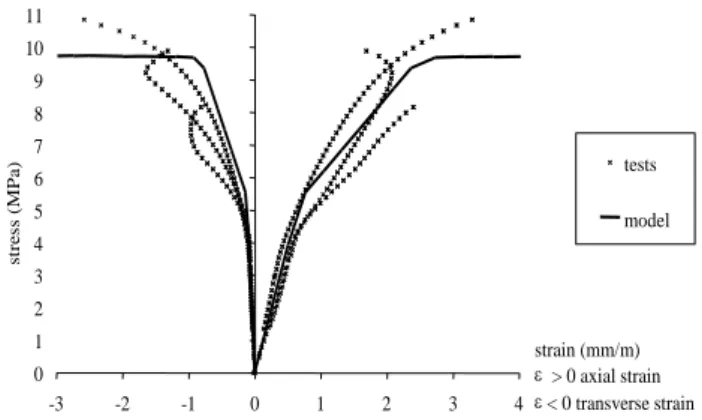
These research works on mortar and on bricks are developed in the thesis of Domede (2008). An elasto-plastic model (Von Mises criterion with bilinear hardening) has been fitted on experimental results. We give the comparison between experimental results and elasto-plastic law in figures 3 and 4.
0 1 2 3 4 5 6 7 8 9 10 11 -3 -2 -1 0 1 2 3 4 strain (mm/m) > 0 axial strain < 0 transverse strain st re ss (MP a ) tests model 0 1 2 3 4 5 6 7 8 9 10 11 -3 -2 -1 0 1 2 3 4 strain (mm/m) > 0 axial strain < 0 transverse strain st re ss (MP a ) tests model
0 4 8 12 16 -2 -1 0 1 2 3 4 strain (mm/m) > 0 axial strain < 0 transverse strain st re ss ( Mpa ) tests model 0 4 8 12 16 -2 -1 0 1 2 3 4 strain (mm/m) > 0 axial strain < 0 transverse strain strain (mm/m) > 0 axial strain < 0 transverse strain st re ss ( Mpa ) tests model
Fig. 4 - Tests and modelling of bricks
(1) Massive element behaviour
To calculate large masonry structures like arch bridges, it is necessary to consider homogenized macro-elements. In this paragraph, we propose a constitutive law for
homogenized masonry usable in the elasticity domain and in compression until the failure. Only compressive failure criterion is included in the massive finite element’s constitutive law; we determined it by an experimental research. The tensile failure is reported to the joints elements.
A homogenization method was used in order to find a suitable model. A Representative Element Volume was defined. It includes mortar joints (about 1 to 2cm thick) and elementary bricks. It was computed under various loading configurations. The comparative study
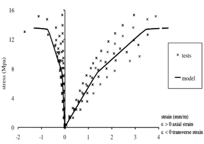
between traditional laws used to describe masonries is given by Domede (2008). The same procedure was applied to the brick masonry, the rubble masonry and the freestone masonry, leading to the homogenized constitutive laws presented in figure 5.
Fig. 5 - Mechanical behaviour of masonries till failure
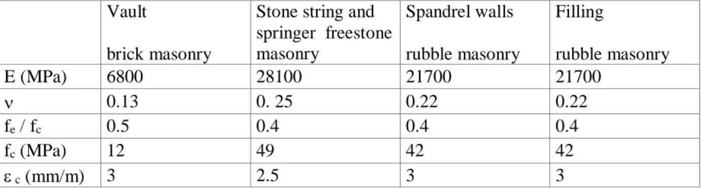
The theoretical model for each of the constitutive materials includes a linear elastic part up to 40% of the strength, followed by a hardening phase based on a Von Mises criterion. The parameters are summarized in table 2. This retained model predicts with a reasonable accuracy the strength of masonry starting from the behaviour laws of its components.
Vault
brick masonry
Stone string and springer freestone masonry Spandrelwalls rubble masonry Filling rubble masonry E (MPa) 6800 28100 21700 21700 0.13 0. 25 0.22 0.22 fe / fc 0.5 0.4 0.4 0.4 fc (MPa) 12 49 42 42 c (mm/m) 3 2.5 3 3
Tab. 2 - Mechanical parameters of masonries
Figure 5 shows that brick vault clearly appeared as the weakest element of the bridge, and not the filling as might have been expected. Indeed, the vault had an elastic modulus and
compressive strength four times lower than the other parts of the bridge. The filling was the most resistant element.
(2) Joint elements behaviour
The theoretical behaviour described previously, associated with the massive finite elements in the computer code used, is elastic in tension and elastic-plastic in compression. But we
observed that the tensile strength is very low and the tensile failure brittle. That is the reason why, in our numerical model, the cracking effects by tension and shearing of the mortar joints are concentrated in joint elements. They represent the behaviour of the interface between the mortar and the brick. The joint elements have a different behaviour in tension and
compression, no elastic limit in compression and a brittle failure in tension as shown in table 4. The failure criterion is of the Coulomb type.
The parameters of the Coulomb model (Tab. 4) were fitted from a Casagrande Box tests (Fig. 6 and 7). The specimens used for these tests were brick cylinders (obtained by boring) with mortar cast on their tops (Fig. 6).
0,0 0,5 1,0 1,5 2,0 -0,2 0 0,2 0,4 0,6 0,8 1 1,2 1,4 s (MPa) t (MPa) 0,11+ sigma tan(49,5°) two months old tests one month old tests
Fig. 7 - Coulomb criterion of interface elements
Cohesion Shear angle Tensile strength 0.1MPa 49° 0.06Mpa
Tab. 4 – Characteristics of the brick-mortar interface.
Bridge finite element analysis
(1) Mesh, loading and boundary conditions
The characteristics of the numerical bridge model were (Fig. 8):
- The mesh of the bridge is requires a few parameters given by the user (position of the centre of the circle describing the vault, level of the foundations, highest level of the walls, radius and angle of the vault, thickness of the vault key, dimensions of the abutments, thickness of the spandrel walls, and width of the brick vault).
- The bridge model consists of 4 different masonry models. Each of them has been presented above.
- The mesh of the masonry is made with 3D massive finite elements for the four models previously described. The joints elements (with the Coulomb criterion) cross the vault and the filling and radiate from the vault axis.
- The bridge can slip on the ground via a joint element positioned between the abutments and the foundation (Fig. 9).
vault filling Stone string and springer Walls and abutments vault filling Stone string and springer Walls and abutments
Fig. 8 - bridge modelling with 4 different masonries
Fig. 9 - Element joints position
We chose to subject the bridge to its own weight (10 MN) and to an off-centre vehicle weight (Fig. 10). The weight was applied on two axles, whose geometry was in conformity with type TS of Eurocode 1. The transverse positioning of this tandem was parameterized. The load was increased until the bridge collapsed.
12 3 4 5 6 7 8 loads 9 10 1112 13 14 15 16 12 3 4 5 6 7 8 9 10 11 121314 15 16 12 3 4 5 6 7 8 loads 9 10 1112 13 14 15 16 12 3 4 5 6 7 8 9 10 11 121314 15 16
Figure 10 - load positions on the bride
(2) Numerical analysis of the bridge
The analysis of the computed results gave major information about the internal effects and the bridge failure. We calculated the bridge with two different boundary conditions, blocked supports or foundation slipping.
If slipping is allowed, the Coulomb joints open, leading to bridge failure with large
displacements of the abutments (Fig. 11). The opening of the joints reaches 1mm at the time of foundation slip. At the time of bridge failure, everywhere in the bridge, the compressive stresses remain moderate compared to the compressive strength of the materials. The most compressed zones of the bridge are the stone string and the angles of the springer (Fig. 12). We conclude that the failure is mainly due to the joints opening in the tensile zones.
If the abutments are blocked, the bridge bearing capacity is increased until longitudinal cracks appear, or until the compression strength of one of the masonry elements is reached. We note that the compressive stress gradient between the stone string and the brick vault creates shear stresses in the interface between these two zones. This is concomitant with transverse tensile stresses. In the contact plane between the arch filling and the stone string unit, shearing and tension are simultaneous, which increases the risk of localized failure. These two phenomena can create longitudinal cracks under the bridge. This is a pathology often observed by bridge owners. According to our calculations, this transverse phenomenon occurs when the vehicle is in a transverse position. Consequently, bridge widening seems to be a worsening factor for this pathology.
slipping slipping
Fig. 11 - Bridge displacements
-3 MPa -2 -1 0 +1 smaxin vault : 6 MPa -3 MPa -2 -1 0 +1 smaxin vault : 6 MPa
Fig. 12 - Bridge stresses while slipping
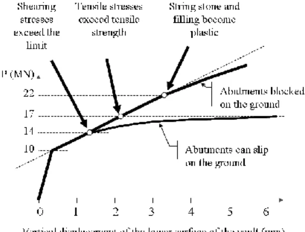
Fig. 17 - Load applied on the bridge according to vertical displacement under the axles, for two kinds of boundary conditions
Conclusion
The methodology described bellow can be summarized in three main steps: material and geometry identification, laboratory tests and homogenized constitutive law fitting, numerical analysis of the bridge. On another bridge, the second step could be changed by tests on cores drilled into the bridge.
The numerical modelling gives a description of the internal effects, from service to failure load, in the three dimensions of the bridge. It takes into account both the nonlinear behaviour of constitutive materials in compression through massive finite elements and brittle cracking in tension or shearing thanks to the joint elements.
The numerical modelling implemented shows the failure mode dependence on the boundary conditions. In the example analyzed, two different failure modes are pointed out: longitudinal cracking between the stone string and the brick vault when foundations are blocked on the ground, transversal cracking when foundation sliding is possible. The compressive strength of the masonries is not involved in collapse.
Unfortunately, we have not been allowed to make full-scale tests on the bridge that we have studied. But a new project is starting with SNCF-RFF which includes in situ tests of a multi span bridge. With this further research, our method and model is about to improve.
References
Boothby T.E., Roberts B.J. (2001), "Transverse behaviour of masonry arch bridges", Structural Engineer, vol.79, n°9, 21-26.
Giordano A., Mele E., De Luca A. (2002), "Modelling of historical masonry structures: comparison of different approaches through a case study", Engineering Structures, vol.24, issue 8, 1057—1069.
Domède N., (2006), Méthode de requalification des ponts en maçonnerie, Doctoral thesis, INSA de Toulouse-LMDC, 202 p.
Domède N., Pons G., Sellier A., Fritih Y., (2008), “Mechanical behaviour of ancient masonry”, accepted for publication on January 14th 2008, in Materials & Structures.
Fanning P.J., Boothby T.E., Roberts B.J., (2001), “Longitudinal and transverse effects in masonry arch assessment”, Construction and Building Materials, vol.15, Issue 1, 51-60. Lanas J. et al. (2004), “Mechanical properties of natural hydraulic lime-based mortars”, in
Cement and concrete research, 34, USA, 2191-2201.
SNCF (Société Nationale des Chemins de Fer français), plans et dossiers de constructions des archives de la Compagnie des Chemins de Fer du Midi, Toulouse.