Publisher’s version / Version de l'éditeur:
Questions? Contact the NRC Publications Archive team at
[email protected]. If you wish to email the authors directly, please see the first page of the publication for their contact information.
https://publications-cnrc.canada.ca/fra/droits
L’accès à ce site Web et l’utilisation de son contenu sont assujettis aux conditions présentées dans le site LISEZ CES CONDITIONS ATTENTIVEMENT AVANT D’UTILISER CE SITE WEB.
Student Report (National Research Council of Canada. Institute for Ocean Technology); no. SR-2007-06, 2007
READ THESE TERMS AND CONDITIONS CAREFULLY BEFORE USING THIS WEBSITE.
https://nrc-publications.canada.ca/eng/copyright
NRC Publications Archive Record / Notice des Archives des publications du CNRC :
https://nrc-publications.canada.ca/eng/view/object/?id=a35a5929-0aa5-4f85-94ba-12720ab1cb27 https://publications-cnrc.canada.ca/fra/voir/objet/?id=a35a5929-0aa5-4f85-94ba-12720ab1cb27
NRC Publications Archive
Archives des publications du CNRC
For the publisher’s version, please access the DOI link below./ Pour consulter la version de l’éditeur, utilisez le lien DOI ci-dessous.
https://doi.org/10.4224/8895045
Access and use of this website and the material on it are subject to the Terms and Conditions set forth at
Pipe in pipe mount design Guy, B.
DOCUMENTATION PAGE
REPORT NUMBER
SR-2007-06
NRC REPORT NUMBER DATE
April 2007
REPORT SECURITY CLASSIFICATION
Unclassified
DISTRIBUTION
Unlimited
TITLE
Pipe-in-Pipe Mount Design AUTHOR(S)
B. Guy
CORPORATE AUTHOR(S)/PERFORMING AGENCY(S)
National Research Council – Institute for Ocean Technology
PUBLICATION
SPONSORING AGENCY(S)
NRC-IOT
IMD PROJECT NUMBER
42_2193_16
NRC FILE NUMBER KEY WORDS
Pipe in pipe, 42_2193_16, Riser, MDTF
PAGES 26 FIGS. 22 TABLES 0 SUMMARY
This project concerns the design of a mounting system for an experimental riser model. Two concepts, a structure and an adapter joint, have been conceived, and the results are shown.
ADDRESS National Research Council
Institute for Ocean Technology Arctic Avenue, P. O. Box 12093 St. John's, NL A1B 3T5
National Research Council Conseil national de recherches
Canada Canada
Institute for Ocean Institut des technologies Technology océaniques
PIPE-IN-PIPE MOUNT DESIGN
SR-2007-06
Brent Guy
Table of Contents
1.0 INTRODUCTION... 4
2.0 PIPE-IN-PIPE RISER SYSTEMS ... 4
2.1 PROJECT OVERVIEW... 4
2.1.1 Purpose ... 5
2.1.2 Collaborators ... 5
2.1.3 Environmental Considerations ... 5
2.2 RISER SYSTEMS CONFIGURATION... 6
2.3 EXPERIMENT... 7
2.3.1 Set-Up ... 7
2.3.2 Instrumentation ... 9
2.3.3 Test Frame Concepts ... 10
3.0 STRUCTURAL CONCEPT ... 10 3.1 OVERVIEW... 10 3.2 TEST FRAME... 10 3.3 DESIGN CONCEPTS... 13 3.4 ANSYS ANALYSIS... 15 3.5 CAD MODEL... 17
4.0 TOW POST ADAPTER CONCEPT ... 19
4.1 OVERVIEW... 19 4.2 DESIGN CONCEPTS... 21 4.3 DESIGN CRITERIA... 23 5.0 FEASIBILITY STUDY ... 25 5.1 RECOMMENDATIONS... 26 6.0 CONCLUSION ... 26
Table of Figures
Figure 1 – Coastal Newfoundland and Labrador... 6
Figure 2 – Free Hanging Configuration... 6
Figure 3 – Pipe-in-Pipe Riser Model ... 8
Figure 4 – Load Cell Mount... 9
Figure 5 – Spacer Assembly ... 9
Figure 6 – Actuator Frame Assembly ... 11
Figure 7 – Actuator Frame Isometric... 11
Figure 8 – Actuator Frame Bottom ... 12
Figure 9 – Actuator Frame Top ... 12
Figure 10 – Structural Concept #1 ... 13
Figure 11 – Structural Concept #2 Profile ... 14
Figure 12 – Structural Concept #2 Top... 14
Figure 13 – Applying Loads to Model... 16
Figure 14 – Mode Shape ... 16
Figure 15 – Structural Design Isometric ... 17
Figure 16 – Structural Design Front ... 18
Figure 17 – MDTF ... 20
Figure 18 – Tow Post Adapter Above ... 20
Figure 19 – Tow Post Adapter Below... 21
Figure 20 – Bolt Pattern Conversion ... 21
Figure 21 – Tow Post Adapter Joint ... 22
1.0 INTRODUCTION
This project is related to the Pipe-in-Pipe (PIP) Riser Systems project being completed by Dr. Ahmed Derradji. Briefly, the project pertains to the attempt to find a suitable mounting system for the experimental pipe being tested in water. Two main concepts have been conceived, one using a structure with a mounted actuator frame, and the other using the Marine Dynamic Test Facility (MDTF) struts attached to the existing tow post adapter, which would oscillate the pipe back and forth. Specifically, the second concept refers to a bolt pattern adapter joint connecting the load cell of the riser to the bottom of the tow post adapter. Both concepts have been considered, modelled, and simulated. The results are shown.
2.0 PIPE-IN-PIPE RISER SYSTEMS 2.1 Project Overview
Project Name: “Performance of pipe-in-pipe riser systems”
Project Number: 42_2193_16
The project concerns the experimental testing of riser systems for use offshore in coastal Newfoundland and Labrador. It is an attempt to measure the effect of such harsh environmental conditions on PIP systems. The tests will be carried out in both air and water, with air setting the standard for all tests thereafter. The pipe system consists of inner and outer pipes, with specifically placed spacers in between. This design should provide superior strength and structural integrity compared to simple, single-pipe designs. The experimental riser system has been both designed and fabricated internally at the Institute for Ocean Technology (IOT), and the experiment is to be performed there as well.
2.1.1 Purpose
The purpose of the experiment is:
A) To determine the fatigue life span and performance of PIP riser systems; B) To compare such performance to that of a single-pipe design.
2.1.2 Collaborators
The collaborators on the project are A. Derradji, I. Konuk, and R. Beresford.
2.1.3 Environmental Considerations
As shown in Figure 1, offshore Newfoundland and Labrador consists of the Grand Banks, Felmish Cap, and Orphan Basin. The existing oil fields in this region are Hibernia, Terra Nova, and White Rose. The ocean environment is known to be typically harsh and rugged. It is characterized by high winds and waves, icebergs, and continuous currents. The presence of high winds makes the region especially harsh and tumultuous. The offshore structures present in these areas must be precisely engineered to be able to withstand such environmental damage. In what is considered one of the most severe ocean locations in the world, it is difficult to design any form of large structures. It is only through simulation and experimentation can one accurately gain a degree of certainty.
Figure 1 – Coastal Newfoundland and Labrador
2.2 Riser Systems Configuration
There are many different types of riser configurations available. The one that has been selected for experimentation is the “Catenary (Free Hanging) Configuration”, shown in Figure 2. It is favourable for its simplicity and low cost, but in some instances can be considered an unrealistic model for extreme weather conditions.
2.3 Experiment
2.3.1 Set-Up
For the tests completed in air, the pipe was to be oscillated back and forth by a hydraulic actuator mounted to a frame. The frame was designed by Trent Slade, and can be seen in Figure 6. The riser model itself is made of standard aluminum, and is shown in Figure 3. Each pipe has a wall thickness of 3.175 mm. The diameter of the outer pipe is 101.6 mm, and the inner diameter is 95.25 mm. The outer pipe has a length of 5.0 m, and the inner pipe measures slightly shorter, at 4.88 m. The spacers, as shown in Figure 5, are located between the two pipes are made of rubber. Rubber was selected to reduce vibrations caused by metal striking metal. The spacers are located every 0.5 m along the length of the model.
Figure 4 – Load Cell Mount
Figure 5 – Spacer Assembly 2.3.2 Instrumentation
The experiment makes use of the following: - yo-yo potentiometer
- load cell - motion sensors - motion pack
2.3.3 Test Frame Concepts
For the experiments in water, a new test frame had to be designed. The two concepts are presented in Sections 3.0 and 4.0.
3.0 STRUCTURAL CONCEPT 3.1 Overview
In the early stages of the experimental phase of the project, there arose a need to develop some form of tower structure for the test frame. A structure that would be made of 6 in. x 6 in. box steel tubing was a viable option. The structure would be mounted to bolt holes in the floor of the Ocean Engineering Basin (OEB). Upon further investigation, it was noted that the existing holes in the floor would not be suitable, as some were previously filled with a silicon substance, and some were not suitably straight. The structure had to be tall enough to allow the pipe to hang freely, and could not be filled with internal cross bracings that would interfere with pipe activity. The top platform of the structure would mount to the bottom footprint of the actuator frame, to be discussed later.
3.2 Test Frame
The test frame supports the hydraulic actuator used to oscillate the riser system, and was designed primarily by Trent Slade. It is shown in Figures 6, 7, 8 and 9. It is simply a box-style hollow frame with four legs. On the bottom of each of the legs is a mounting pattern.
Figure 6 – Actuator Frame Assembly
Figure 8 – Actuator Frame Bottom
3.3 Design Concepts
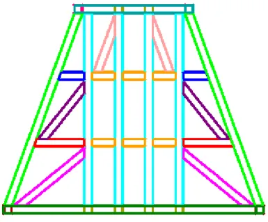
Two concepts were proposed. Shown in Figure 10, the first concept consisted of a webbed front and back, with hollow interior and side sections, and bracings running across the top and bottom. The second design was a four-legged structure with bracings in the vertices. It provided a lot of room for pipe activity and camera visibility, as well as strength in the direction perpendicular to pipe motion. Notice, in Figure 11, that the square bracing on the bottom of the structure is elevated slightly.
Figure 11 – Structural Concept #2 Profile
Figure 12 – Structural Concept #2 Top
In the end it was decided that the first concept would be most suitable, as the deflection values (see Section 3.4 ANSYS Analysis) in the second concept were too large. After some additional bracings were added, the final concept was to be rendered in a CAD environment. Only after viewing the design on a more realistic scale, would it be selected for production.
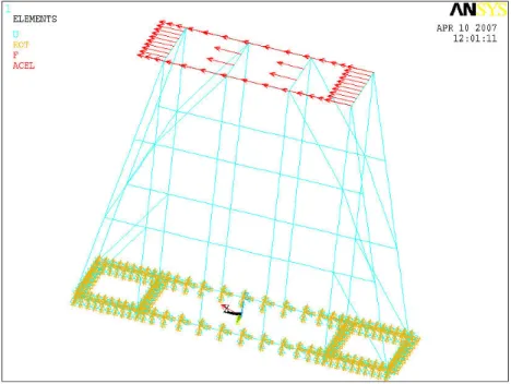
3.4 ANSYS Analysis
ANSYS is a finite element analysis (FEA) software package. FEA is a numerical method of deconstructing a complex system into smaller pieces. It is best known for its applications in mechanical design. It can determine stress, strain, and deflection modes, determine buckling loads and mode shapes, and even analyse thermal or electromagnetic behaviour. To keep the discussion succinct, the following two diagrams address the simulation adequately. In Figure 13, the red arrows are the applied horizontal loads, which simulate the oscillation of the hydraulic actuator. The bottom of the structure is fixed, as though it were mounted to the floor. The simulation is started, and in Figure 14 one can see the mode shape, of how the structure bends and deflects under the load condition applied. These deflections are exaggerated in the current image, and the exaggeration scale is user-determined. For the ANSYS code used for the simulation, see Appendices.
Figure 13 – Applying Loads to Model
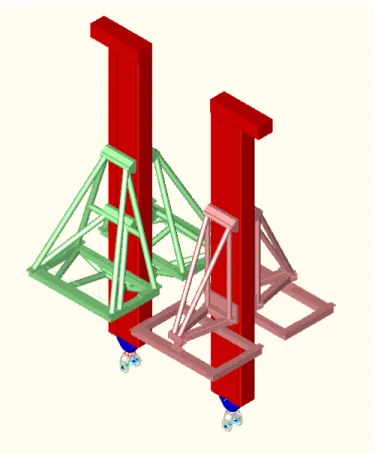
3.5 CAD Model
The following images are the rendered model of the structure proposed:
Figure 16 – Structural Design Front
The faults in using a structure appeared after rendering. Due to the sheer size of the structure, and the dimensions of the tubing, it was obvious that the structure would be quite heavy, hard to manufacture, and would have extremely decreased visibility throughout. Such conditions certainly did not seem ideal for the project at hand.
4.0 TOW POST ADAPTER CONCEPT 4.1 Overview
During the analysis of the fabrication drawings for the structural concept, Dr. Derradji became aware of a second option for an experimental set-up. By making use of the Marine Dynamic Test Facility in the Clearwater Tow Tank (CWTT), a set-up could be devised such that the struts of the MDTF (see Figure 17) would oscillate the pipe. The pipe would be attached to the tow post adapter (see Figure 18), and allowed to hang down into the tank. The approximate depth of the tank is 7.0 m, a suitable height, so all that was required was a way to connect the pipe to the tow post adapter. In Figure 19, the existing circular bolt pattern located on the bottom of the tow post adapter is shown. A joint was to be designed which would connect this circular pattern to the square pattern on the top of the pipe’s load cell.
Figure 17 – MDTF
Figure 19 – Tow Post Adapter Below
Figure 20 – Bolt Pattern Conversion
4.2 Design Concepts
The conception of this design was straightforward. At first glance, perhaps a simple plate with both patterns drilled in it would be suitable. But installation becomes a problem. Hence, the concept followed that consisted of a circular plate, a square plate, and a midsection pipe. The top and bottom plates had the coordinated bolt patterns on them, with the circular pattern threaded, and the bottom drilled. The length of the midsection pipe was determined by ease of installation, and the thickness of each plate
was approximately determined by inquiries directed to the manufacturer of the load cell. After such dimensions were reiterated with ANSYS analysis. Figure 21 shows the design. For accurate dimensions and tolerances, see Appendices.
Figure 21 – Tow Post Adapter Joint
When bolted to the adapter, it appears as shown in Figure 22. Braces have also been added to the tow post adapter itself, to provide more strength. The dimensions and tolerance of the tow post adapter have been included in Appendix B – Detailed Fabrication Drawings.
Figure 22 – Tow Post Adapter Assembly
4.3 Design Criteria
The joint was required to join the circular bolt pattern on the tow post adapter with the square bolt pattern on top of the AMTI MC8 Series load cell, which is connected to the top of the testing pipe.
The accuracy of the hole locations for the bolt patterns had to be precise, especially due to the uncertainty attributed to the fact that the circular pattern was already existing. Upon measurement of the pattern, it was noticed that some of the holes were off by a small fraction, so any deviance in the top flange of the joint could prove to be a problem. The load cell’s square pattern was easier to design for, considering the locations of the holes are extremely precise, and the dimensions can be found on the AMTI website. The height of the joint was not required to be as accurate, as long as it was noted in the final design specs.
The dimensions of the flanges are oversized from the bolt locations at convenient values. The midsection pipe was already in stock at IOT, and was cut to a reasonable
1.0 inch. After consulting a member of the AMTI support staff, they replied that a 1.0 inch thick plate would suffice provided it was built to dimensions of the top of the cell. For ease of manufacturing, the same thickness of plate was repeated for the top flange, with adequate strength considerations.
There has been room accounted for in the general design of the joint for installation. The top will be bolted down through a hollow section in the middle of the top post adapter, and the load cell will be bolted on in the four corners of the bottom flange. For the top flange 3/4-10 UNC bolts will be used, and 5/8-11 UNC bolts for the bottom flange.
The joint will be made out of steel, and two 1/8 fillet welds will be made around the outer circumference of the midsection pipe, joining both flanges to it.
5.0 FEASIBILITY STUDY
In order to determine which concept was more appropriate for selection for manufacturing, a feasibility study had to be invoked. Topics range from cost to performance, and in the end it allows the designer to select the concept that will best fit the need.
Concept # 1: Structure Concept # 2: Tow Post Adapter
Hard Cash: $ 7,500 Hard Cash: $ 1,000
Fabrication Time: 1,000 hrs Fabrication Time: 75 hrs $50,000 $4,000 No option to increase riser length Option to double length of riser Test Location: OEB Test Location: CWTT Availability: Fair Availability: Poor Risk Factor: HIGH Risk Factor: Moderate to Low
Problems: Problems:
•Weight of structure •Strut strength •Footprint location •MDTF performance •Pump on platform •Installation cost
•Oil contamination •Cost of repeating experiment •Heating of pump at high power
5.1 Recommendations
1) Select the Tow Post Adapter concept for production.
2) Keep the Structural concept open until it is determined how the MDTF will perform.
6.0 CONCLUSION
This project has been a perfect example of how a design can evolve, and end up becoming almost unrecognizable upon conclusion. For example, it was presumed that the test frame supporting the hydraulic actuator was necessary for usage. Therefore, initially only reasonable concept appeared to be a structural one. Shortly thereafter, the notion of using the MDTF in conjunction with the tow post adapter became a viable option, and the structure actually became a concept that was vastly over-engineered and costly. In the end, the design was very simple, and cost a considerable amount less than the prior one. This is an indication that when designing a project, one should truly spend the most time conceiving rather than designing and plugging resources into materials and manufacturing. It is the planning that truly results in optimal designs, and when one has the most ideal conception of how to approach the problem, the design process itself becomes a rather quick and confident procedure. In the case of this project, the problem of determining the proper way to support the experimental pipe was solved in what I believe is the most efficient and simple manner.