Publisher’s version / Version de l'éditeur:
Vous avez des questions? Nous pouvons vous aider. Pour communiquer directement avec un auteur, consultez la première page de la revue dans laquelle son article a été publié afin de trouver ses coordonnées. Si vous n’arrivez pas à les repérer, communiquez avec nous à [email protected].
Questions? Contact the NRC Publications Archive team at
[email protected]. If you wish to email the authors directly, please see the first page of the publication for their contact information.
https://publications-cnrc.canada.ca/fra/droits
L’accès à ce site Web et l’utilisation de son contenu sont assujettis aux conditions présentées dans le site LISEZ CES CONDITIONS ATTENTIVEMENT AVANT D’UTILISER CE SITE WEB.
6th Construction Specialty Conference [Proceedings], pp. 1-10, 2005-06-01
READ THESE TERMS AND CONDITIONS CAREFULLY BEFORE USING THIS WEBSITE. https://nrc-publications.canada.ca/eng/copyright
NRC Publications Archive Record / Notice des Archives des publications du CNRC :
https://nrc-publications.canada.ca/eng/view/object/?id=c4df3c30-f8ae-498f-8013-44b0aa6b5a47 https://publications-cnrc.canada.ca/fra/voir/objet/?id=c4df3c30-f8ae-498f-8013-44b0aa6b5a47
NRC Publications Archive
Archives des publications du CNRC
This publication could be one of several versions: author’s original, accepted manuscript or the publisher’s version. / La version de cette publication peut être l’une des suivantes : la version prépublication de l’auteur, la version acceptée du manuscrit ou la version de l’éditeur.
Access and use of this website and the material on it are subject to the Terms and Conditions set forth at
Integration of data and processes of AEC projects using the industry
foundation classes
Integration of data and processes of AEC projects
using the industry foundation classes
Halfawy, M.; Froese, T.
NRCC-48131
A version of this document is published in / Une version de ce document se trouve dans :
6
thConstruction Specialty Conference, Toronto, Ont., June 2-4, 2005, pp. 1-10
6th Construction Specialty Conference 6e Conférence spécialisée sur le génie de la construction
Toronto, Ontario, Canada
June 2-4, 2005 / 2-4 juin 2005
INTEGRATION OF DATA AND PROCESSES OF AEC PROJECTS
USING THE INDUSTRY FOUNDATION CLASSES
Mahmoud Halfawy1 and Thomas Froese2
1. Centre for Sustainable Infrastructure Research, Institute for Research in Construction, National Research Council, Regina, SK, Canada; formerly, Department of Civil Engineering, University of British Columbia, Vancouver, BC, Canada.
2. Department of Civil Engineering, University of British Columbia, Vancouver, BC, Canada
ABSTRACT: Integration trends in the Architectural, Engineering, and Construction (AEC) industry are increasing the demands for the implementation and deployment of integrated project systems. Much of the research throughout the last decade was driven by the need to develop integrated project systems and standard industry-wide data models to support their development. Standard data models are widely recognized as the main enabling technology to develop integrated AEC systems. Most notable of these models is the Industry Foundation Classes (IFC), developed by the International Alliance of Interoperability (IAI). This paper presents an implementation of the IFC classes to support the full integration of AEC projects data and processes. The paper also discusses an approach to link project design, scheduling, and cost data, and to enable bi-directional exchange of data between different systems.
1. INTRODUCTION
Fragmentation of the Architecture, Engineering, and Construction (AEC) industry has caused many problems that could be primarily attributed to the “gaps” between the design, construction, and facility management phases of a project. Project information typically flows from the design phase to the construction to the facility management phase, with very costly and time consuming feedback loops in the form of change orders during the construction phase, or excessive maintenance work during the facility management phase. Information gaps and lack of efficient information management throughout the facility lifecycle have often resulted in additional cost and time, reduced quality and productivity, loss of design intent, and the inability to access and communicate information in a timely fashion.
Experience with project and information gaps, along with factors related to competition and economic pressures, have created an increasing demand for adopting approaches that would achieve the integration of different project processes. The industry has been steadily moving towards adopting methods that can potentially integrate different project processes (e.g. adopting design-build). This trend has created even more demand for software systems to support this integration. As a result, software tools have been moving to become more open through providing access to their internal data models, adopting model-based techniques, or by supporting industry wide standard data models. Adopting integrated project delivery approaches supported by integrated software systems will undoubtedly lead to reducing design-construction cycle time, and to improve the overall lifecycle efficiency, performance, and maintainability of facilities. An integrated approach would also result in less change orders and re-work during the construction phase, and more efficient maintenance and management operations throughout the life of the facility (Halfawy 1998).
Model-based data standards have long been recognized as the main enabling technology for developing integrated AEC project systems (Halfawy 1998, Halfawy and Froese 2002). During the past decade, several efforts have been underway to develop standard data models to support interoperability and data exchange among software applications (Froese and Yu 1999). Object-based data models typically define schemas that represent the structure and organization of project data in the form of a class hierarchy of objects. The use of an object model has significantly improved the consistency of project information, and served to integrate different project aspects and facilitate the exchange of project information.
Over the years, several data models have reached a high level of maturity in supporting a wide range of project aspects. Most notable of these models is the Industry Foundation Classes (IFC), developed by the Industry Alliance for Interoperability (IAI 2005). Examples of other models include: CIMSteel CIS/2 for steel construction projects, PCSC pre-cast concrete model, AP225, and aecXML. Many commercial software tools already support several of these standard data models.
IFC represents the largest scale effort to standardize AEC data. The latest IFC release (version 2x Edition 2) has significantly extended the core model to support areas such as structural steel, reinforced concrete, precast concrete, and structural analysis, among others. Efforts are ongoing to link and interface IFC with other data models in order to extend the scope and utility of the model. Like many other standardization efforts, IFC is based on ISO STEP data modeling standards. The IFC schema defines the main objects and relationships that cover core project information such as building elements, the geometry and material properties of building products, project costs, schedules, and organizations. Instances of the IFC entities are initialized, linked, and assembled by applications to create an object model of the project. The IFC is considered to be a mature and comprehensive model that is widely supported and accepted by the industry. The IFC explicitly model a variety of project information (project costs, schedules, and organization) in addition to the facility physical products. However, the vast majority of existing IFC implementations primarily support the modeling and exchange of the building product information. As a result, the project management classes, and in particular the scheduling classes, of the IFC schema remain almost entirely untested.
In this paper, we present an approach to support efficient sharing and management of project information, and to enable the integration and interoperation of various domain-specific software applications through developing and maintaining an integrated project repository based on the IFC data model. A proof-of-concept implementation of the approach will also be discussed.
2. REQUIREMENTS OF INTEGRATED AEC SYSTEMS
Integrated project systems are fairly complicated software systems and, despite many years of research and development, the AEC industry has yet to develop a complete understanding of their architecture, features, and implementation requirements. A fundamental requirement of integrated project systems is to support an open, modular architecture and non-proprietary, possibly standard, data models that allow various applications to plug into the system and to interoperate and exchange data with other applications. Integrated project systems should support the management of the project data and documents across all project disciplines and throughout the project lifecycle. Also, implementation should take into consideration a number of factors pertaining to the project organization and size, available technologies, and suitable modes of data sharing. The suitability of an approach for a particular class of projects would depend on their specific characteristics and data management requirements. Obviously, no single architecture would be appropriate throughout the industry and any solution should be developed to provide a flexible and customizable environment that can be adapted to accommodate possible project scenarios.
Another key requirement is to support the integration of various project processes and the enabling of efficient information flow between these processes. AEC projects typically involve many inter-dependent activities that need to be managed and coordinated. An integrated system should support the integration and interoperation of an array of function-specific software applications that support various project
activities. The system should also assist in modeling and implementing workflows to enable the efficient flow of information among various project processes.
AEC projects typically involve the generation and manipulation of dynamic and large data sets with complex interrelated objects. An integrated project system is required to maintain the consistency and integrity of project data, especially when users could access the data concurrently, by implementing procedures to propagate and manage changes to project data. Also, the system should support industry-wide data modeling standards if they exist. The system should support different modes of data access and exchange such as file exchange, centralized database, application-to-application data exchange, and online web access. Also, due to the evolutionary and iterative nature of project processes, the system should enable users to define objects at multiple levels of details and enable the management of changes and versioning of these objects.
3. AN IFC-BASED APPROACH FOR IMPLEMENTING INTEGRATED PROJECT DATA REPOSITORIES
Undoubtedly, the most important requirement of an integrated AEC project system is to build and maintain a project data repository that integrates and supports various aspects of the project. This repository would ensure the consistency and integrity of project data, enable efficient data sharing and exchange, support tools interoperability, and enable team collaboration and timely access to project information. The repository would also allow downstream project activities to access the design information to evaluate and assess the impact of design decisions from the perspective of downstream project activities.
Although the IFC explicitly model a variety of project information beyond the facility physical products, the vast majority of existing IFC implementations imports the building product information, and use the product model to generate some other project information (e.g. bill of material), but they do not record the additional project information back into the IFC files to be available for other applications. As a result, the project management classes of the IFC schema remain almost entirely untested. Despite the fact that the project information in IFC files are based on a standard schema, this approach does not differ much from the traditional sequential approach where design data files are exchanged using other neutral file formats. In both cases, design data flows in a uni-directional manner. An integrated project repository should support the flow of project information across all project processes and throughout the project life cycle. The IFC define a flexible and powerful mechanism to allow extending the model through the use of the IfcPropertySet entity. An IFC property set could be used to define a set of properties (IfcProperty entities or other nested IfcPropertySet entities). A property set can be linked to any number of IFC objects using the IfcRelAssignsProperties entity. Using this approach, we could, for example, define a property set that describes the specifications of a building element and link this set to the IfcProduct entity that represents this building element using an IfcRelAssignsProperties entity. Similarly, information that support cost estimating, construction planning, or facilities management can be easily linked to the facility IFC objects. In addition to its extensibility, the IFC model also enables linking a wide range of project information, represented as IfcObject entities, through the use of IfcRelationship-derived entities. IFC uses objectified relationships to describe association among various objects in the model. For example, the IfcRelProcessOperatesOn entity could be used to link construction activities to the facility products that they operate on. Also, an IfcRelSequence entity could be used to specify the precedence relationship between two project activities.
The IFC mechanisms to link multi-disciplinary project information and to extend the data model beyond its defined scope makes it an ideal data model to support the implementation of integrated project systems. In our particular approach, we have used the IFC schema to incrementally develop a centralized integrated project data model that enables the interoperation of various function-specific tools and the exchange of project information among different project disciplines.
A typical project would start by a small set of conceptual design entities that can be used to exchange the design information with a wide range of function-specific software tools that span different project
disciplines. As a result of incremental generation and linking of project information, an integrated “project model” would be evolved. This integrated project model would represent a comprehensive view of the project and would glue together various project data and processes.
Given the evolutionary nature of the project processes (i.e. evolving from conceptual to preliminary to detailed stages), the integrated project model will evolve and grow as the project progresses. The evolution of the project processes and the growth of project information can be depicted using a spiral model (Figure 1). The central axis in the model represents the project model, which starts from a simple conceptual product model and evolves into a more comprehensive and detailed project model as more iterations are performed over the life cycle of the project. Each project activity generates more information in a particular aspect and links this information back to the IFC project repository.
I F C - B a s e d P r o j e c t M o d e l
Arc hite ctu ral De sign H VA C De s ig n B O M / C o s t E s tima tin g Str uct ura l/ Fo und atio n De sig n Pro jec t Info rma t ion Gro wth Ov e r Tim eF u l l y I n t e g r a t e d
I F C P r o j e c t M o d e l
S im u la tio n P lan ning / S che du ling P r oj e c t D o cu m e n ts S ite M o d e lin g/ P la n n ingI F C - B a s e d P r o j e c t M o d e l
Arc hite ctu ral De sign H VA C De s ig n B O M / C o s t E s tima tin g Str uct ura l/ Fo und atio n De sig n Pro jec t Info rma t ion Gro wth Ov e r Tim eF u l l y I n t e g r a t e d
I F C P r o j e c t M o d e l
S im u la tio n P lan ning / S che du ling P r oj e c t D o cu m e n ts S ite M o d e lin g/ P la n n ingFigure 1: Spiral Model of Information Evolution in Project Repositories
The following scenario illustrates a typical use of the IFC-based project repository. Suppose that a preliminary architectural design is developed and a number of IFC design entities are defined. The design software generates an IFC model and exports the IFC design data to the centralized project. Cost estimating, scheduling, and specification software import the design data, generate more IFC-based project information, and link this information together as well as with the project model that was initially used. Project participants from different disciplines could access the IFC project description and view data in their respective domains and any other dependent or related data in other domains. As project actors modify portions of the project data, the repository would ensure the consistency and integrity of the project model through the use of integrity constraints as well as by tracking the globally unique identifiers of the IFC objects. By recognizing the relationships between various project entities, the repository would also implement methods to ensure that the project data are consistent or to determine whether any interdependent objects need to be updated. These methods could range from simple techniques to notify parties that might be affected by a change, to more sophisticated techniques to automate change propagation and conflict detection/resolution mechanisms. Multi-disciplinary project actors could also use the integrated project model to assess dependencies and interactions between different project aspects,
and to collaborate to evaluate decisions and resolve conflicts. Clearly, this scenario demonstrates how an integrated project system can effectively support a multi-disciplinary approach to AEC projects.
4. IMPLEMENTING DATA AND PROCESS MANAGEMENT SERVICES IN IFC-BASED INTEGRATED SYSTEMS
Data management services in an integrated project system are required to support data sharing and interoperability between various applications and users of the system through maintaining an interface to the centralized project repository. The project repository contains the specific project objects instances and documents describing a project. The following are some of the data services that could be supported through the data management services. A component or an application that requests access to the project data is termed as “data client.”
• Queries and Transactions: The repository supports the ability for the data client to run both short and long transactions.
• Data Sets: A data client can request a specific dataset (e.g., the ID of a particular project). The repository provides methods for managing datasets, such as creating new ones, copying data sets, etc.
• Data Access: To read information from the repository, a data client passes some type of data query and receives a resulting dataset. To write information to the repository, the data client sends a dataset to the repository. The repository should support at least a few basic query mechanisms, such as the ability to return a complete model, the ability to return a specific object instance only, and the ability to return all objects of a specified class.
Primarily, a repository can be implemented in two main forms depending on the required level of data management functionality: using simple IFC files; or using a centralized Database Management System (DBMS). The repository may be implemented to support local and/or web-based data access.
Current implementations of IFC-based integration rely almost exclusively on the application-to-application exchange of IFC files (STEP Part21 physical files or XML files). However, simple file-based data exchange is very limited in its scalability and ability to manage a large pool of shared project information or to support the data management functionality required by large AEC projects. Also, due to the evolutionary nature of AEC projects, sharing project data using files makes it very difficult to control or track changes and versions of the data. File exchange is not well suited for large scale project data sharing since it requires exchanging the entire project model despite the fact that an application or project participant would typically require access to a limited view of the integrated project model. Limitations of file-based project repository could be addressed by using a centralized DBMS.
A centralized DBMS-based project repository is essential to support sharing and exchange of project information while being accessed concurrently by many users and applications. The DBMS would enable implementing a variety of data management services that are typically required for large-scale integrated project systems. Besides the basic services for ensuring the data integrity, more advanced services (e.g. version management and control, concurrency control, data distribution, security and authorization, meta-data services, etc.) can also be implemented. Users and different applications will be able to access the same project data concurrently while the system will maintain and ensure the consistency and integrity of the data. Besides supporting advanced data management functionality, an DBMS would eliminate the need to parse and access the entire project model by enabling the exchange partial project models and supporting transactional forms of data exchange between project parties and applications. Users and applications could simply query the DBMS to retrieve the specific objects related to their respective views or disciplines.
Although modern object-based AEC systems support the modeling of a large portion of project information in the form of objects, the vast majority of project information is still represented and exchanged in the form of unstructured documents. Examples of these documents include design drawings, analysis calculations, bill of materials, specifications, schedules, contracts, etc. Data management services,
besides managing object-based structured project data, should be extended to support the management of project documents.
Document management services involve the use of a set of document attributes structured in what is termed as “metadata.” Besides generic attributes such as document author, date, topic, etc., a document metadata should also define some project-specific attributes that would enable easy and efficient search and retrieval of documents pertaining to a specific subject. Although standards exist for defining the generic attributes of documents, e.g. (Dublin Core Metadata Initiative 2005), no standard is available for defining AEC documents metadata. Therefore, document management services would need to define a set of metadata attributes that effectively describe an AEC project document, and establish a bi-directional link between these attributes and the objects in the project model, and thus enabling context-based access to documents directly from the object model.
A third form of project data exchange that is becoming more commonplace in the industry is the use of transactions. A large amount of project information could be modeled in the form of transactions (online or offline). Transaction examples include: requesting or querying product or schedule data, submitting a change order, electronic tendering and procurement, materials management, resource scheduling, and site reporting information (Halfawy et al 2002). Systems that support transactions in the AEC industry are almost non-existent and are mainly based on the Electronic Data Interchange (EDI) standards. Organizations have used EDI to support their data processing tasks and to automate the exchange of data across their organizational boundaries in the form of standard transactions. (Almeido et al 1998) reported that there are 28 generic EDI messages that can be used in the construction industry, 12 of which were developed specifically for the construction industry. These messages mainly cover tendering, establishment of contract, materials management, accounting, and drawing administration. In spite of the many research efforts that have been conducted during the past several years to introduce EDI to the construction industry, very limited success has been achieved (Almeido et al 1998). Traditionally, the cost of proprietary EDI software and hardware needed made it infeasible to many AEC organizations to implement and maintain EDI systems. Moreover, the lack of an industry-wide standard project information model, such as IFC, caused EDI applications to be limited to address project processes related to procurement and tendering. However, the emergence of web-based standards and the ongoing efforts to base EDI systems on XML as well as the availability of the standard IFC data model are expected to change this picture in the near future.
AEC project processes are typically very complex and involve a large number of actors working with and communicating inter-dependent chunks of project data in various forms as described above. Such interdependencies necessitate defining rules and procedures to manage and coordinate the information flow and the workflow within the project. The workflow management services would implement methods to support the modeling and implementation of these rules and procedures. A substantial body of knowledge is currently available that addresses the analysis and modeling of the workflow of AEC project processes. Workflow models would provide a comprehensive view of different software applications, information requirements and flow patterns, and to identify the interface and data exchange requirements between various project activities.
An integrated project system is required to support the modeling, integration, and management of the three aforementioned forms of project data as well as to implement services to manage projects activities and workflows. Although the availability of comprehensive industry-wide data models, such as IFC, has enabled the development of novel approaches to support the integration of AEC projects, more work is still needed to fine tune, harmonize, and implement these approaches, and to test their applicability in real project environments.
5. INTEGRATION OF DESIGN AND PROJECT MANAGEMENT INFORMATION: PROTOTYPE IMPLEMENTATION
In a typical AEC project, significant interdependencies and complex relationships exist between design, scheduling, and cost estimating data. The data pertinent to each of these areas are generated and
managed by separate software applications that operate in somewhat isolated “silos.” A critical functionality of an integrated project system is to link and manage the inter-dependencies of these data, and to enable different applications to share these data through the use of the integrated project model. In our prototype implementation, we developed adapters for three commercial software systems to demonstrate the mapping and integration of AEC project data across these key project activities using the IFC data model. The software systems used included Architectural Desktop for architectural design, Microsoft Project for construction scheduling, and Timberline Precision for cost estimating. Adapters were developed to perform the mapping of the internal representation of the project data in these applications to and from the IFC schema. The implementation detail (e.g. language, methodology) of each application adapter would depend on the specific Application Programming Interface (API) provided or the component interfaces exposed by the application. The following three sections summarize the implementation of each of these adapters.
5.1. Architectural Desktop Adapter
The Architectural Desktop adapter is developed using the Object ARX class library. The adapter added a menu interface in ADT where different mapping functions could be accessed. Users could import an IFC file where the adapter will map the IFC objects to the corresponding ADT entities. Almost all IFC architectural design entities have corresponding ADT objects. For example, an IfcWall object can be easily mapped to an AecWall entity where the wall dimensions are extracted from the IfcWall geometric representation attributes and used to create the ADT wall object.
5.2. Microsoft Project Adapter
The Microsoft Project adapter was implemented as a COM add-in that added a menu interface to the application where data mapping functions can be accessed. A standalone and a web-based version of the adapter were also developed. The adapter maps the application entities to IFC entities as follows:
• Each Task is mapped to IfcTask
• Task schedule times are mapped to IfcScheduleTimeControl
• The project is mapped to IfcWorkSchedule
• Tasks are assigned to the schedule using an instance of IfcRelAssignsTasks for each task
• Task nesting is mapped using the IfcRelNests
• Each Resource is mapped to IfcResource (IfcCrewResource or IfcConstructionMaterialResource)
• Precedence relationships are mapped using IfcRelSequence
• Resource assignments are mapped using IfcRelUsesResource
• An instance of IfcProject is created and the IfcScheduleTimeControl is assigned to the project using an instance of IfcRelAssignsToControl
Construction tasks (IfcTask entities) are (manually) linked to facility products (IfcBuildingElement entities) by defining IfcRelAssignsToProcess entities where the RelatedObjects attribute references the instance of IfcBuildingElement and the RelatingProcess attribute references the related IfcTask entity. Linking products and tasks enables users to easily access tasks related to a specific product, and to retrieve all products related to a specific task. It also enables the 4D visual simulation of the construction sequence and to view the projected status at any point during the construction process. 4D simulation could provide construction planners with an insight into the construction process to identify potential conflicts and evaluate the interaction between various activities.
5.3. Timberline Precision Estimating Adapter
An adapter was developed to access Precision’s cost estimating database. The adapter was implemented as standalone software that accesses the cost estimating database using Timberline’s ODBC driver and Microsoft Active Data Objects (ADO) classes. The adapter maps the entities of a Precision cost estimate to IFC entities as follows:
• The estimate is mapped to an instance of IfcCostSchedule
• Each cost item is mapped to IfcCostElement
• Each assembly is mapped to an instance of IfcCostElement that nests other IfcCostElement entities using an instance of IfcRelNestsCostElements
Although IFC’s cost estimating classes are not as rich as the scheduling classes, many cost-related data could be modeled and integrated using the IFC schema. Cost items and assemblies (IfcCost entities) can be linked to facility products (IfcBuildingElement entities) by defining IfcRelCostsObjects entities where the RelatingControl attribute references an instance of IfcCost and the RelatedObjects attribute references the related instance of IfcBuildingElement. Linking products and costs enables users to access cost items related to a specific product, and to find all products that relate to a specific cost item. It also enables easy calculation of the cost of any particular product. Another benefit of this integration is the ability to automatically calculate materials quantities from product models and to map these values to the cost element attributes. Cost element’s quantities related to other cost categories (e.g. labor, subcontractor, etc.) can be derived from the product materials quantity. IFC currently do not support some important aspects of cost estimating process, in particular the definition of multiple cost categories per cost element, and the support of parametric estimating where variables and formulae are used for takeoff and estimating of parametric assemblies and cost elements. Future releases of IFC should address this limitation.
5.4. Mapping Application Data for Bi-directional Exchange
A common issue with almost all adapters is that the number of attributes of a particular object represented using a function-specific application will be much more than the number of attributes defined for a corresponding IFC entity. Although this might seem as a limitation in the IFC schema, our experience with the prototype showed that the mapping of common attributes was sufficient for the purposes of integration and data exchange between various project domains. It is worth noting that the IFC schema was not intended to represent all possible attributes for a particular object. Rather, IFC was primarily intended as a core model that supports the common overlapping area between various project disciplines in order to facilitate easy integration and data exchange. However, in order to maintain consistency in bi-directional data exchange and enable better data management between different sessions, a mechanism that links an IFC instance with its application-specific counterpart needs to be established and implemented in the adapter of that application. In many existing adapters where data is exchanged, or translated, from the application’s data model to IFC in a uni-directional manner, this issue is not addressed. However, to enable bi-directional data exchange and the use of the IFC data model at various stages of the project lifecycle where data exchange will need to be performed in several sessions, this mechanism is needed. In our implementation, the adapters mapped the Globally Unique Identifier (GUID) of IFC instances onto an application-specific user-defined attribute of the corresponding object. When data imported or exported, the adapter uses this information to detect if a particular object was added, deleted, or modified. The user is provided with a list of detected changes and given the option to accept, reject, or override changes. Consequently, an application’s data and the corresponding IFC file are kept synchronized.
5.5. Integrating Design, Schedules, and Cost Estimates
Although linking products and tasks, and linking products and costs were clearly supported by the IFC data model, the link between tasks and costs were not as clear, and was found to be cumbersome to achieve. Cost elements related to tasks (i.e. resources used by the task) are represented using instances of IfcRelUsesResource which link tasks to a related resource and assigns costs to the ResourceUseCosts attribute. This link would result in a resource-driven cost estimate that could be used to calculate cash flow and resource requirements based on the projected schedule. However, a project cost estimate is typically product-driven where products are mapped to cost items and assemblies to estimate the project cost. In a typical product-driven cost estimate, tasks are implicitly represented in the cost items. Unifying or harmonizing the product-driven and resource-driven cost estimating approaches where products-tasks-costs are explicitly represented and linked would provide a more consistent and homogeneous cost estimating process.
One possibility of a unified cost estimating system is to make all cost elements resource-driven. That is, resources will be assigned not only to tasks but to products as well, using instances of
IfcRelUsesResource, which will link any number of tasks or products with a particular resource. The quantity, duration, waste factor, and cost attributes of the resource can be specified in the IfcRelUsesResource instances. Then, an IfcCost instance will be created for each IfcRelUsesResource instance. Therefore, to Calculate the element or extension cost of a specific product, the application would retrieve all IfcRelUsesResource instances related to this product (one instance for each resource), retrieve the attributes of the product or the resource (which might be described using property sets), applies formulas and equations to calculate the cost values, and then assigns these values to the attributes of the corresponding IfcCost entities. A similar procedure would be used to find the cost of a particular task. By standardizing the definition of products, tasks, resources, and related property sets, integrated applications that establish these links will be able to automate the propagation of any changes in the product design or specification to related cost elements and schedule tasks. A disadvantage of this approach is that the direct link between the products and cost items that was represented by instances of IfcRelCostsObjects will become an indirect one that would require extra processing to map the cost items to the products. However, the disassociation of the products and cost elements will result in a more consistent and homogeneous resource-based cost estimating process that can be used to link products, tasks, resources, and cost elements.
5.6. Example System Use
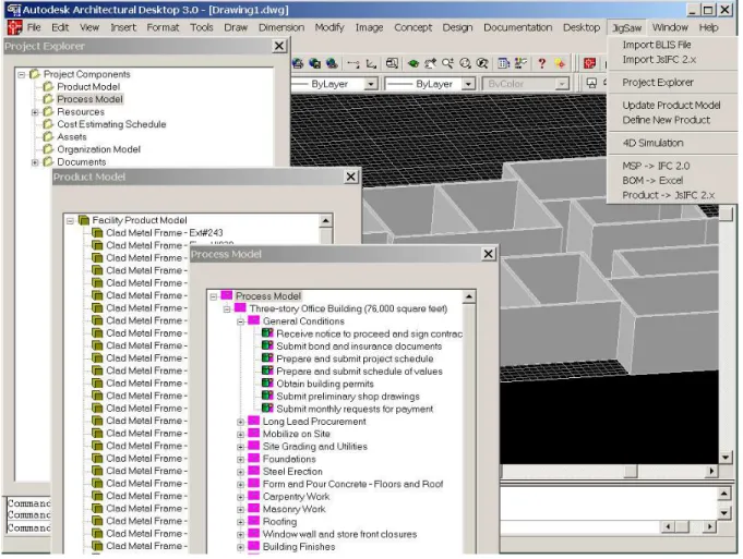
The following scenario illustrates a typical use of the prototype system. First, a preliminary architectural design is developed and a number of IFC design objects are defined. The CAD software generates an IFC model and exports the design data into a standard IFC STEP part 21 file which is added to the project repository. Cost estimating and scheduling software would import the design data, generate more IFC-based project information, and link this information back with the project model that was initially used. The project repository will integrate the different project aspects and maintain the relationships among IFC objects (e.g. linking cost and schedule data to building elements). Project actors from different disciplines could access the project model and view data in their respective domains, along with any other related information in other domains. Actors could use this integrated project view to assess interactions and dependencies between various project activities, and resolve conflicts and inconsistencies at early stages of the project. Figure 2 shows an example project modeled using the prototype system.
The prototype enables users to manage and navigate through project information through a tree-like “project explorer” interface. This interface represents project views in a hierarchical tree structure and employs the services provided by the data management component to access various pieces of project information such as the facility product model, resources, schedule, and cost estimate. Users could link project information among various project views to indicate relationships between different elements of project data. The project explorer enables users to link related objects by a simple drag-and-drop operation to link products, tasks, and cost items.
6. CONCLUSIONS
Development and deployment of integrated AEC project systems is becoming a major driving force in the AEC software market. After many years of research and development, the AEC industry has now started to embrace and adopt the systems that support and promote concepts of integration and interoperability. It is largely recognized that technologies that support integration of AEC projects data and processes hold the promise of increased productivity and improved quality of construction projects.
This paper presented an attempt to develop an integration approach based on standard object-based project data model, namely the IFC. Several issues and lessons derived from implementing the proposed approach have been discussed, and ideas for further extension of the approach were also outlined. Our next effort will be directed towards full development and implementation of these ideas.
The authors gratefully acknowledge support for this work from the Natural Sciences and Engineering Research Council of Canada, Collaborative Research Opportunities Program.
Figure 2: Integrated Project Data Using the IFC Project Repository
8. REFERENCES
Almeido, L, Grilo, A., Rabe, L., and Duin, H. 1998. Implementing EDI and STEP in the construction industry,” proceedings of Product and Process Modeling in the Building Industry, ECPPM’98, R.Amor (Editor), BRE.
Froese, T., and Yu, K., 1999. Industry Foundation Class Modelling For Estimating And Scheduling,
Durability Of Building Materials And Components 8. Vancouver, May 1999. Vol. 4, pp. 2825-2835 Halfawy, M., Pouria, A. and Froese, T. 2002. Developing Message-Based Interoperability Protocols for
Distributed AEC/FM Systems. CIB W78 Conference, Aarhus, Denmark, June 12-14.
Halfawy, M.R. and Froese, T. 2002. “A Component-Based Framework for Integrated AEC/FM Project Systems,” To appear in the proceedings of the CSCE 2002 Conference of the Canadian Society for Civil Engineers, Montreal, Canada, June 5-8.
Halfawy, M.R. 1998. A Multi-Agent Collaborative Framework for Concurrent Design of Constructed Facilities, Ph.D. Dissertation, Department of Civil and Environmental Engineering and Geodetic Science, the Ohio State University.
IAI 2005. International Alliance for Interoperability, Industry Foundation Classes – IFC 2x. On-line documentation. http://www.iai-international.org (Last Accessed January 2005).