Publisher’s version / Version de l'éditeur:
Optics Express, 17, 9, pp. 7702-7707, 2009
READ THESE TERMS AND CONDITIONS CAREFULLY BEFORE USING THIS WEBSITE. https://nrc-publications.canada.ca/eng/copyright
Vous avez des questions? Nous pouvons vous aider. Pour communiquer directement avec un auteur, consultez la première page de la revue dans laquelle son article a été publié afin de trouver ses coordonnées. Si vous n’arrivez pas à les repérer, communiquez avec nous à [email protected].
Questions? Contact the NRC Publications Archive team at
[email protected]. If you wish to email the authors directly, please see the first page of the publication for their contact information.
NRC Publications Archive
Archives des publications du CNRC
This publication could be one of several versions: author’s original, accepted manuscript or the publisher’s version. / La version de cette publication peut être l’une des suivantes : la version prépublication de l’auteur, la version acceptée du manuscrit ou la version de l’éditeur.
For the publisher’s version, please access the DOI link below./ Pour consulter la version de l’éditeur, utilisez le lien DOI ci-dessous.
https://doi.org/10.1364/OE.17.007702
Access and use of this website and the material on it are subject to the Terms and Conditions set forth at
Continuous-wave optical parametric oscillator tuned by a diffraction
grating
Vainio, Markku; Siltanen, Mikael; Peltola, Jari; Halonen, Lauri
https://publications-cnrc.canada.ca/fra/droits
L’accès à ce site Web et l’utilisation de son contenu sont assujettis aux conditions présentées dans le site LISEZ CES CONDITIONS ATTENTIVEMENT AVANT D’UTILISER CE SITE WEB.
NRC Publications Record / Notice d'Archives des publications de CNRC:
https://nrc-publications.canada.ca/eng/view/object/?id=44165276-4471-4a62-911a-42a201648f41 https://publications-cnrc.canada.ca/fra/voir/objet/?id=44165276-4471-4a62-911a-42a201648f41Continuous-wave optical parametric
oscillator tuned by a diffraction grating
Markku Vainio,1,2Mikael Siltanen,1Jari Peltola,1and Lauri Halonen1,∗
1Laboratory of Physical Chemistry, P. O. Box 55 (A.I. Virtasen aukio 1),
FIN-00014 University of Helsinki, Finland
2Current address: Institute for National Measurement Standards,
National Research Council, Ottawa, Canada K1A 0R6
∗Corresponding author:[email protected]
Abstract: A new continuous-wave singly resonant optical parametric os-cillator is described. It is capable of stable, widely tunable single-frequency output in the mid-infrared region. A magnesium oxide doped periodically poled LiNbO3 crystal provides the parametric amplification. The signal beam is in resonance with a 4-mirror linear cavity, where a diffraction grating in the Littrow configuration replaces one end mirror. The output frequency is tunable by rotating the grating. No additional components are needed inside the resonator.
© 2009 Optical Society of America
OCIS codes:(190.4970) Parametric oscillators and amplifiers; (140.3600) Lasers, tunable.
References and links
1. G. D. Boyd and D. A. Kleinman, “Parametric interaction of focused Gaussian light beams,” J. Appl. Phys. 39, 3597–3639 (1968).
2. A. K. Y. Ngai, S. T. Persijn, G. von Basum, and F. J. M. Harren, “Automatically tunable continuous-wave optical parametric oscillator for high-resolution spectroscopy and sensitive trace-gas detection,” Appl. Phys. B 85, 173– 180 (2006).
3. S. T. Lin, Y. Y. Lin, Y. C. Huang, A. C. Chiang, and J. T. Shy, “Observation of thermal-induced optical guiding and bistability in a mid-IR continuous-wave, singly resonant optical parametric oscillator,” Opt. Lett. 33, 2338– 2340 (2008).
4. M. Vainio, J. Peltola, S. Persijn, F. J. M. Harren, and L. Halonen, “Singly resonant cw OPO with simple wave-length tuning,” Opt. Express 16, 11141–11146 (2008).
5. J. Kiessling, R. Sowade, I. Breunig, K. Buse, and V. Dierolf, “Cascaded optical parametric oscillations generating tunable terahertz waves in periodically poled lithium niobate crystals,” Opt. Express 17, 87–91 (2009). 6. R. Sowade, I. Breunig, J. Kiessling, and K. Buse, “Influence of the pump threshold on the single-frequency output
power of singly resonant optical parametric oscillators,” Appl. Phys. B (2009).
7. L. B. Kreuzer, “Single and multimode oscillation of the singly resonant optical parametric oscillator,” in Pro-ceedings of the Joint Conference on Lasers and Opto-Electronics, pp. 52–63 (The Institution of Electronic and Radio Engineers, 1969). Revised Edition.
8. S. E. Bisson, K. M. Armstrong, T. J. Kulp, and M. Hartings, “Broadly tunable, mode-hop-tuned cw optical parametric oscillator based on periodically poled lithium niobate,” Appl. Opt. 40, 6049–6055 (2001).
9. M. van Herpen, S. te Linkel Hekkert, S. E. Bisson, and F. J. M. Harren, “Wide single-mode tuning of a 3.0-3.8-µm, 700-mW, continuous-wave Nd:YAG-pumped optical parametric oscillator based on periodically poled
lithium niobate,” Opt. Lett. 27, 640–642 (2002).
10. M. M. J. W. van Herpen, S. Li, S. E. Bisson, S. te Lintel Hekkert, and F. J. M. Harren, “Tuning and stability of a continuous-wave mid-infrared high-power single resonant optical parametric oscillator,” Appl. Phys. B 75, 329–333 (2002).
11. D. Stothard, I. Lindsay, and M. Dunn, “Continuous-wave pump-enhanced optical parametric oscillator with ring resonator for wide and continuous tuning of single-frequency radiation,” Opt. Express 12, 502–511 (2004).
12. D. C. Hanna, M. V. O’Connor, M. A. Watson, and D. P. Shepherd, “Synchronously pumped optical parametric oscillator with diffraction-grating tuning,” J. Phys. D 34, 2440–2454 (2001).
13. B. Jacobsson, V. Pasiskevicius, F. Laurell, E. Rotari, V. Smirnov, and L. Glebov, “Tunable narrowband optical parametric oscillator using a transversely chirped Bragg grating,” Opt. Lett. 34, 449–451 (2009).
14. H. Kogelnik and T. Linkel, “Laser beams and resonators,” Appl. Opt. 5, 1550–1566 (1966).
15. M. Vainio, J. Peltola, S. Persijn, F. J. M. Harren, and L. Halonen, “Thermal effects in singly resonant continuous-wave optical parametric oscillators,” Appl. Phys. B 94, 411–427 (2009).
16. A. Henderson and R. Stafford, “Intra-cavity power effects in singly resonant cw OPOs,” Appl. Phys. B 85, 181– 184 (2006).
1. Introduction
The operation of continuous-wave optical parametric oscillators (cw OPOs) is based on a non-linear optical effect called parametric amplification [1]. An intense pump beam (angular fre-quencyω1) and a signal beam (angular frequencyω2, such thatω1>ω2) are focused into a nonlinear medium where some of the pump beam photons are converted to the frequency of the signal beam, which is thereby amplified. In addition, for every photon created at the signal frequencyω2, another photon is created at the idler frequencyω3=ω1−ω2, thus generating the idler beam. The idler frequency can be tuned by adjusting either the pump beam frequency (pump tuning) or the signal beam frequency (signal tuning). It is often easier to tune the fre-quency of the signal beam because pump tuning is limited by the properties of the pump laser. Ultimately, the tuning range is limited by the nonlinear medium, which must support suffi-ciently strong parametric amplification for the frequencies involved. This amplification must exceed the threshold determined by the losses in the OPO in order for it to operate.
Structured nonlinear crystals such as MgO-doped, periodically poled LiNbO3(MgO:PPLN) are commonly used to produce an idler beam at infrared wavelengths around 2-4 µm [2–6]. The crystal is placed inside an oscillator cavity with one, two, or three beams in resonance.
Singly resonant OPOs (SROs), i.e., those with only one of the three beams in resonance, possess several advantages over OPOs with more than one beam in resonance [7]. SROs are simpler to build and to tune, and are capable of higher maximum output powers, although the pump power threshold is also higher. The output power of an SRO can be further increased, without losing single-mode operation, by setting the pump power threshold above the lowest possible value [6].
Previously, intra-cavity etalons have been employed in cw SROs [2, 8–11]. The variation to the effective parametric amplification introduced by this additional component is periodic with respect to the signal beam frequency. While etalons can be used to improve stability and to allow signal tuning, they also increase intra-cavity losses, introduce walk-offs to the resonating beam, and can cause tuning-dependent power variations. Furthermore, the tuning range provided by an intra-cavity etalon is limited. Recently, it has been shown that a stable cw SRO can be designed and constructed without an etalon or other additional components inside the oscillator cavity [4]. Slow tuning can then be achieved by varying the temperature of the periodically poled crystal, or by moving the crystal to change the poling period, or both. Pump tuning allows fast frequency changes in the OPO output; however, it depends on the characteristics of the pump laser.
In this paper, we report a new cw SRO, where the frequency of the resonating signal beam (and therefore the frequency of the idler beam) is tuned by a rotatable diffraction grating that replaces one of the end mirrors of the linear oscillator cavity. Gratings and Bragg reflectors have been used in pulsed devices before [12, 13], but to our knowledge, this is the first instance a diffraction grating being used to tune a cw OPO. The grating allows rapid tuning of the signal beam frequency across the whole range allowed by the MgO:PPLN crystal without the addition of intra-cavity components such as etalons. We have measured wide tunability of the idler
frequency with a constant pump frequency and fixed crystal temperature. Our grating-tunable cw OPO (GOPO) is also capable of single-mode operation and good long-term stability.
2. Experimental details
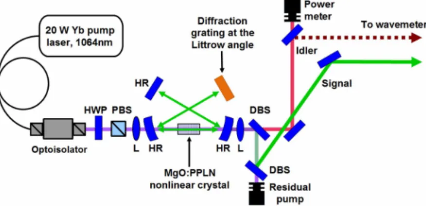
Fig. 1. The layout of the linear cavity setup of the GOPO. The symbol HWP denotes a half-wave plate, PBS a polarizing beam splitter, L a lens, HR a highly reflecting mirror, and DBS a dichroic beam splitter. The distance between the concave mirrors is 138 mm and the distances between the concave mirrors and the ends of the cavity are 270 mm.
The layout of the optical setup is shown in Fig. 1 and the details of the OPO cavity geometry can be found in earlier reports [14, 15]. The cavity is singly resonant [7] for the signal fre-quency. There is a congruent LiNbO3crystal doped with 5 mol-% of MgO (HC Photonics) in the center of the resonator cavity. The MgO:PPLN crystal is 50 mm long and 1 mm thick with parallel regions of different poling periods. We have mostly used a poling period of 31.5 µm in our measurements. The pump, signal, and idler beams pass longitudinally through the crystal. The entry and exit surfaces of the crystal are cut at an angle of 1 degree to prevent residual etalon effects. The crystal surfaces are anti-reflection coated for the pump, signal, and idler frequencies. Thermoelectric coolers set the MgO:PPLN crystal temperature between 20◦C and 120◦C with a stability of ±6 mK.
A pair of concave mirrors with a radius of curvature of 100 mm encloses the MgO:PPLN crystal. The inside surfaces are coated (Quality Thin Films) so that their nominal reflectance is over 99.9% at the signal frequency and less than 0.5% at the idler frequency. The outside surfaces are convex and coated to maximize the transmission of the pump, signal, and idler beams in order to minimize residual etalon effects.
One of the cavity end mirrors is flat with a reflectance of over 99.9% at the signal frequency. In place of the other flat mirror, there is a gold-coated diffraction grating (Newport 53004ZD02-269H) in the Littrow configuration, i.e., the angles of the incident and diffracted beams are equal. The first diffraction order is used as high diffraction efficiencies (≥ 95%) are more eas-ily reached than in higher diffraction orders. The high diffraction efficiency reduces the optical losses of the OPO cavity so that the oscillation threshold can be reached with currently avail-able single frequency pump lasers. The grating possesses 900 grooves per mm and is mounted on a motorized stage, which can be rotated in order to vary the angle of incidence of the sig-nal beam. The frequency corresponding to the Littrow configuration depends on the angle of incidence and can therefore be tuned by rotating the motorized stage. The grating is in the Lit-trow configuration only for the signal beam frequency. Therefore, it reflects no light at the idler frequency back into the cavity, which precludes any weak doubly resonant operation.
The pump beam at 1064 nm is provided by a Yb fiber laser (IPG Photonics) with a maximum optical power of about 21.5 W. The cavity dimensions correspond to a focusing parameter [1] of 2.05 for the resonating signal beam. The value of the focusing parameter of the pump beam is matched to that of the signal beam to facilitate efficient pumping. The theoretical waist radius of the signal beam inside the MgO:PPLN crystal is calculated to be about 56 µm. The idler and residual pump beams and a fraction of the signal beam propagate through the concave mirror at the output of the GOPO. The three beams are then separated by dichroic mirrors. The output powers are measured using a power meter (Newport) and the frequencies are determined using a wavemeter (Exfo WA-1500).
3. Results and discussion
We have measured several properties of the GOPO. To demonstrate tunability, the idler fre-quency was recorded while the grating was rotated at several different temperatures of the MgO:PPLN crystal. We replaced the grating with a flat mirror and placed an etalon within the cavity in order to directly compare the tunability of our grating-tuned OPO with intra-cavity etalon-tuned versions.
The pump laser and the GOPO operate in a single longitudal mode. It is known that when a singly resonant OPO is pumped sufficiently above threshold, single mode operation is not main-tained [5, 7, 16]. This can be prevented by increasing losses, e. g., by lowering the reflectance of the output coupler for the resonating frequency. In our current setup, the reflectance of the grating at the signal frequency is modest, only about 95%. Therefore, a highly reflecting output coupler mirror can be used without risking multimode operation at higher pump powers.
Fig. 2. (a) A typical measured frequency of the output idler beam of the GOPO while rotating the diffraction grating (crystal temperature 118◦C). (b) Comparison of frequency tuning for three tuning elements: two YAG etalons of different thickness and the diffraction grating (crystal temperature 120◦C).
An advantage of the GOPO is its broad frequency tunability. The idler frequency was recorded while rotating the grating at different temperatures of the MgO:PPLN crystal. A typi-cal result is shown in Fig. 2(a), where the tuning range exceeds 500 GHz. Although mode-hops are unavoidable and occur even in opposite directions, their magnitude is reasonable. The inset in Fig. 2(a) shows a distribution of the differences of adjacent points of the tuning curve. A typ-ical mode-hop is a few GHz, which is similar to what we have previously observed with another OPO design, and also with shorter cavities [4]. This is larger than the single free spectral range (FSR, ∼200 MHz) of the cavity. Pump tuning can cover this frequency gap if a continuous scan of the spectrum is required. The GOPO is able to access the whole bandwidth of parametric amplification, which exceeds the oscillation threshold for the specific poling period and
tem-perature. The total wavelength tuning range of the OPO is the same as with a similar OPO without the grating: signal and idler wavelength regions of 1.54–1.76 µm and 2.7–3.45 µm, re-spectively, can be covered by using the poling periods 30.5, 31.0, and 31.5 µm and by tuning the crystal temperature from 20◦C to 120◦C. It is possible to synchronize the temperature tuning rate with grating angle tuning in order to achieve uninterrupted scans larger than that shown in Fig. 2. The tuning rate must be kept slow in order to avoid multi-mode operation during the scans due to crystal temperature gradients. Faster and more reliable tuning is obtained by tuning the crystal temperature in steps [4] and by covering the frequency gaps between the steps with grating rotation.
When an intra-cavity etalon is used to control the frequency of cw OPO, the available tun-ing range for a fixed poltun-ing period and temperature is not as large as in the GOPO. The fre-quency dependence with a grating is also more linear than with an etalon. Figure 2(b) shows the idler frequency of the GOPO recorded while rotating the grating and the results of a sim-ilar OPO that is tuned by rotating 1.0 mm and 0.4 mm thick intra-cavity etalons. The etalons are uncoated polished discs of YAG crystal. The setups differ in the tuning element, which in the GOPO is a diffraction grating and in the OPO is an etalon. For a given etalon, the tuning range is approximately equal to its FSR because the signal frequency of the OPO may jump to an adjacent transmission maximum of the etalon. Attempting to increase the tuning range of an etalon-tuned OPO by decreasing the etalon thickness has the side-effect of broadening the transmission peaks, which in turn leads to a decrease in frequency selectivity. The GOPO, on the other hand, does not suffer from such jumps because the grating possesses only a single reflectance maximum. One can decrease the width of the transmission peaks when using a thin etalon by increasing the reflectivity of the etalon surfaces. This, however, also has a negative consequence: namely increased losses in the cavity. The result of these conditions is that there is an optimal etalon thickness for a given set of OPO parameters. In our case this is about 0.4 mm [8], which is the thickness of one of the etalons used. An air-spaced etalon allows the etalon finesse and FSR to be optimized separately. They provide more linear and larger fre-quency scans with high resolution than solid etalons. However, the benefits of an air-spaced etalon come at the expense of higher insertion losses.
The advantage of a diffraction grating over an etalon for the tuning of the SRO is most evident near degeneracy, where the frequencies of the signal and idler beams are equal. The range of frequencies where a single poling period and fixed crystal temperature can provide sufficient parametric amplification for the OPO to operate is thousands of GHz near degeneracy. In this case, simple etalon tuning does not reliably force the OPO to oscillate at a single frequency due to the multiple etalon modes within the range. The probability of multimode operation and spontaneous mode-hopping is increased. The diffraction grating, however, supports only one reflectance maximum. Consequently, frequency selectivity is preserved in the GOPO.
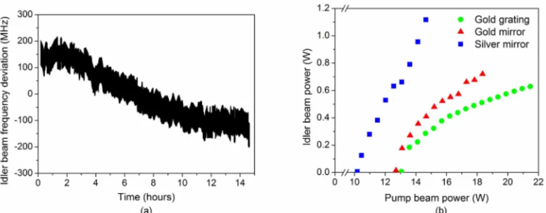
The stability of the GOPO is excellent. As seen in Fig. 3(a), we have measured a frequency drift of about 250 MHz during mode-hop free operation for 14 hours, which is comparable to that of the etalon-free cw OPO reported earlier [15]. Figure 3(b) shows the measured idler output power of the GOPO as a function of the pump power, which is measured just before the GOPO. The idler power values are corrected for losses induced by the optical components between the GOPO output and the power meter. The oscillation threshold for this specific con-figuration is reached by increasing the pump power to about 13 W. About half a watt of output power is easily achieved, but the overall output power and efficiency of the GOPO vary de-pending on where the signal beam hits the grating or mirror surfaces. At high pump power, the signal beam inside the cavity can reach intensities high enough to damage the gold coating of the grating. This and the high losses are potential problems if the power of the GOPO is increased. Nevertheless, these limitations are more technical than fundamental in nature.
Fig. 3. (a) The long-term stability of the GOPO. The GOPO cavity is enclosed inside a plastic protective housing to reduce the effects of ambient air currents. In this measurement, the drift of the idler frequency over 14 hours is about 250 MHz without mode-hops. The resolution of the wavemeter is about 80 MHz. (b) The power of the output idler beam as a function of the pump power with different components at the end of the OPO cavity.
We have performed tests that indicate that a silver instead of gold coating would improve the efficiency of the diffraction grating. No such grating was available for our experiments at this time. However, an estimate of the effect could be made by measuring the output power with the grating replaced by a gold or silver coated flat mirror. The results are shown in Fig. 3(b) along with those of the gold grating. The oscillation threshold with the gold mirror is almost as high as with the grating: about 12.5 W. This is expected, since the reflectivity of the gold mirror is only slightly higher than that of the gold-coated grating. For the flat silver mirror, the threshold was below 10 W. At higher pump powers, the idler power rises steeply and reaches values above 1 W. Ultimately, the pump power is limited by the damage threshold of the mirror. It is possible that the operation of the GOPO could be improved further by using a grating with a dielectric surface and high damage threshold.
4. Conclusions
We demonstrate a stable singly resonant grating-tunable continuous-wave optical parametric oscillator capable of high power idler output in the mid-infrared region. By using a rotatable diffraction grating for the resonating signal beam, it is possible to tune the idler output without disturbing the pump beam characteristics or the temperature of the nonlinear crystal. Our GOPO is free of the limited tunability associated with etalons and their multiple transmission maxima. The GOPO can be tuned over the whole bandwidth range provided by the nonlinear medium in a specific configuration. Although gratings have been used previously in pulsed OPOs this is, to our knowledge, the first report of a cw OPO based on a diffraction grating.
Acknowledgements