AXIOMATIC DESIGN AND NETWORK PERFORMANCE ANALYSIS FOR APPLICATIONS IN HOME-BASED HEALTH CARE
by
JASON DOUGLAS HINTERSTEINER
S.B., Mechanical Engineering
Massachusetts Institute of Technology, 1996
Submitted to the Department of Mechanical Engineering in Partial Fulfillment of the Requirements
for the Degree of
MASTER OF SCIENCE IN MECHANICAL ENGINEERING
at the
Massachusetts Institute of Technology February, 1998
© 1997 Massachusetts Institute of Technology All rights reserved.
Signature of Author
I
Certified by
Department of Mechanical Engineering December 16, 1997
Kai Yeung Sunny Siu Assistant Professor of Mechanical Engineering sis Supervisor Accepted by
Ain A. Sonin Chairman, Departmental Graduate Committee
APk 2 74
40
A_ .' _
~-To Mom and Dad, for everything, and to Nancy, for being there.
-2-AXIOMATIC DESIGN AND NETWORK PERFORMANCE ANALYSIS FOR APPLICATIONS IN HOME-BASED HEALTH CARE
by
JASON DOUGLAS HINTERSTEINER S.B. Mechanical Engineering
Massachusetts Institute of Technology, 1996
Submitted to the Department of Mechanical Engineering on December 16, 1997 in partial fulfillment of the requirements for
the Degree of Master of Science in Mechanical Engineering ABSTRACT
Home-based health care systems of the future will be designed to enable patients to live independently with the aid of electromechanical devices, without the presence of expensive on-site health care professionals. Nevertheless, there will still exist a need for a patient's health to be monitored in real-time, so that a sudden deterioration of a patient's condition can be responded to immediately. Such monitoring Vill ultimately save lives, prevent or minimize medical complications, and thereby ultimately lower health care costs.
Utilizing the resources and rapid growth of communication networks such as the Internet, constant monitoring of home-based patients is achievable. A "telenursing system" has been designed which can obtain real-time sensor data from patients and their home environments and transmit it over the network to a central monitoring facility staffed by nurses and medical technicians. The system also incorporates network applications, such as video conferencing as well as remote access to patient medical records, in order to facilitate remote diagnosis and early detection of medical problems. The axiomatic design approach was used to create the telenursing system design.
To provide network quality of service to medically-related data, the system design incorporates the use of RSVP, an emerging Internet protocol that reserves resources along the network path from senders to receivers. A simulation model of RSVP has been developed which incorporates two different methods (unicast and multicast) for reserving network resources. This model can determine the practicality of RSVP for use in large-scale network applications where real-time interactive data transmission is essential. Thesis Supervisor: Dr. Kai Yeung Sunny Siu
Title: Assistant Professor of Mechanical Engineering
-3-TABLE OF CONTENTS
Abstract 3 Table of Contents 4 Table of Figures 7 Table of Tables 8 Biography 9 Acknowledgments 10 CHAPTER 1: INTRODUCTION 111.1 Home-Based Health Care 14
1.2 Guaranteeing Quality of Service (QoS) 16
1.3 Telenursing System 17
1.4 Network Simulation Model 18
1.5 Previous Work 19
1.5.1 Monitoring System Design 19
1.5.2 RSVP Simulation Models 20
CHAPTER 2: NETWORK QUALITY OF SERVICE 23
2.1 Fundamental Networking Issues 24
2.1.1 Throughput 24
2.1.2 Delay 25
2.1.3 Fairness 26
2.2 QoS Control Services 28
2.2.1 Controlled-Load Service 31
2.2.2 Guaranteed Service 33
2.3 Overview of RSVP 35
2.3.1 Reservation Styles 36
2.3.2 Using RSVP with QoS Control Services 39
2.3.2.1 Sender-TSPEC 40
2.3.2.2 Adspec 40
2.3.2.3 Flowspec 41
2.3.3 Control Messages 41
2.3.3.1 Path Messages and Path State 42 2.3.3.2 Resv Messages and Reservation State 43
2.3.3.3 Teardown Messages 44
2.3.3.4 Error Messages 45
2.3.3.5 Confirmation Messages 45
2.3.4 Traffic Control 46
-4-2.4 QoS Routing 4S
2.4.1 Unicast Routing: OSPF 48
2.4.2 Multicast Routing 51
2.4.2.1 IGMP 51
2.4.2.2 MOSPF 52
2.4.3 QoS Routing 53
CHAPTER
3:
AXIOMATIC DESIGN OF THE TELENURSING SYSTEM 573.1 Overview of Axiomatic Design 58
3.1.1 Problem Definition 59
3.1.2 Creative Process 60
3.1.3 Analytical Process 61
3.1.3.1 The Independence Axiom 61
3.1.3.2 The Information Axiom 64
3.1.4 Ultimate Check 65
3.2 Design of the Telenursing System 65
3.2.1 Modular Interface with Home-Based Sensors (DPI) 70
3.2.2 External Application Interface (DP2) 73
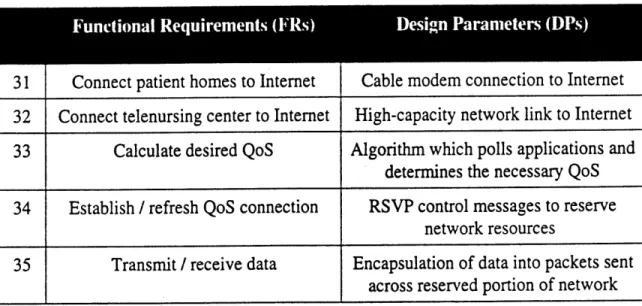
3.2.3 Network Interface (DP3) 77
3.2.4 Computer-assisted Health Care Practitioner (DP4) 84
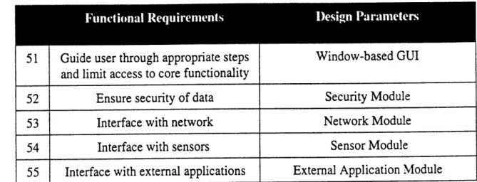
3.2.5 Graphical User Interface (DP5) 88
3.2.5.1 Window-based GUI 89
3.2.5.2 Security Module 90
3.2.5.3 Network Module 91
3.2.5.4 Sensor Module 92
3.2.5.5 External Application Module 92
3.3 Overall System Design 93
CHAPTER
4:
NETWORK SIMULATION MODEL 974.1 Overview of OPNET 97 4.2 Establishing Reservations 98 4.2.1 Multicast-Interactive Reservations 99 4.2.2 Unicast-Interactive Reservations 100 4.3 Simulation Model 102 4.3.1 Establish a Session ID 105
4.3.2 Sending a Path Message 106
4.3.3 Sending a Resv Message 108
4.3.4 Sending Data Messages 111
4.3.5 Ending the Reservation 112
-5-4.4 Network Model
CHAPTER 5: CONCLUSION 119
5.1 Future Work on the Telenursing System Design 120
5.2 Future Work on the Simulation Model 121
APPEN-DICES:
A: Specification of the TSPEC 123
B: Process Model Descriptions 125
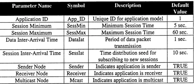
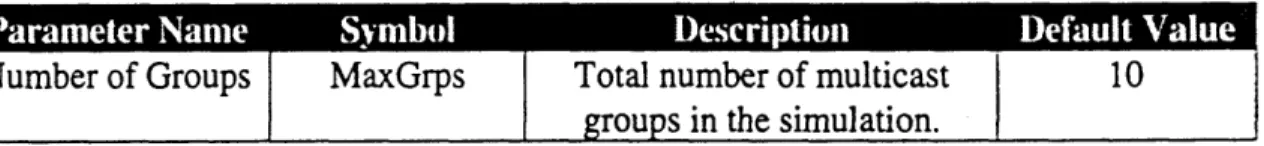
B.1 Host Reserve Application (Host_rapp) 125
B.2 Host Unicast Non-Reserve Application (Host_uapp) 129
B.3 Host RSVP Daemon (Host_rsvpd) 131
B.4 Host Multicast Daemon (Host_igmpd) 135
B.5 IP Network Layer (Rsvp_IP) 138
B.6 Router RSVP Daemon (Router_rsvpd) 140
B.7 Router Multicast Daemon (Router_igmpd) 144
B.8 Router Transmission Queue 146
C: Packet Formats 149
C.1: Host Process Model Formats 149
C.2: RSVP Daemon Process Model Formats 150
D: RFCs and Internet-Drafts 155 E: List of Abbreviations 156 ENDNOTES: Chapter 1 159 Chapter 2 160 Chapter 3 161 Chapter 4 162 -6-113
TABLE OF FIGURES
CHAPTER1:
1-1: CHAPTER 2: 2-1: 2-2: 2-3: 2-4: 2-5: 2-6: CHAPTER 3: 3-1: 3-2: 3-3: 3-4: 3-5: 3-6: CHAPTER 4: 4-1: 4-2: 4-3: 4-4: 4-5: 4-6: 4-7: 4-8: 4-9: 4-10:Schematic diagram of the telenursing system.
Throughput characterization. Example of queuing delay.
The fairness problem for a DQDB network.
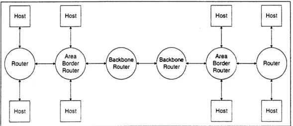
Example of flow merging in an FF-style reservation. Schematic diagram of RSVP in a host and router. Schematic diagram showing different router types.
Information analysis graph.
Schematic diagram of cable modem internet connection. Tree diagram for the telenursing system (FRs).
Tree diagram for the telenursing system (DPs).
Module-junction structure diagram for the telenursing system. Flow chart diagram for the telenursing system.
Multicast-interactive reservation model for two nodes. Unicast interactive reservation model.
Telenursing center host node (ethernet). Telenursing center gateway node (ethernet). Backbone router.
Telenursing center subnetwork configuration (ethernet). Network topography for connected telenursing subnetworks. Network topography of a cable-modem network.
Sample metropolitan telenursing system network topology. Sample rural telenursing system network topology.
APPENDICES:
B-1: State transition diagram for the B-2: State transition diagram for the B-3: State transition diagram for the B-4: State transition diagram for the B-5: State transition diagram for the B-6: State transition diagram for the B-7: State transition diagram for the B-8: State transition diagram for the
host reserve application.
host unicast non-reserve application. host RSVP daemon.
host IGMP daemon. IP network layer. router RSVP daemon. router IGMP daemon. router transmission queue.
-7-12 24 26 27 39 47 50 80 81 94 94 95 96 99 101 102 103 104 114 115 115 116 117 126 130 132 135 138 141 144 147
TABLE OF TABLES
CHAPTER 2: 2-1: 2-2: CHAPTER 3: 3-1: 3-2: 3-3: 3-4: 3-5: 3-6: 3-7: 3-8: 3-9: 3-10: 3-11:Reservation styles available in RSVP.
Reservation requests and aggregate reservation states.
Core functional requirement for the telenursing system. Top-level functional requirements.
Decomposition of interface with home-based sensors (DP 1). Decomposition of interface with external applications (DP2). Decomposition of interface with network (DP3).
Information content of networking technologies for the home. Decomposition of computer-assisted telenurse (DP4).
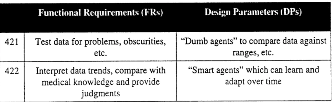
Decomposition of computerized agents (DP42). Decomposition of graphical user interface (DP5). Decomposition of security module (DP52). Decomposition of network module (DP53).
3-12: Junction types and relationships for system architecture diagrams. 95
CHAPTER 4:
4-1: 4-2:
Format of Path State Block (PSB).
Format of Reservation State Block (RSB).
APPENDICES:
B-1: Application parameters for the host reserve application.
B-2: Application parameters for the host unicast non-reserve application. B-3: Action taken when a packet arrives from the host's RSVP daemon. B-4: Action taken upon packet arrival from a host reserve application. B-5: Action taken upon packet arrival from the IP network layer. B-6: Application parameters for the host's IGMP daemon. B-7: Application parameters for the IP network layer.
B-8: Action taken upon packet arrives from the IP network layer. B-9: Application parameters for the router's IGMP daemon.
107 110 127 127 130 132 134 136 139 142 145 37 39 66 66 70 74 79 81 85 86 89 90 92
BIOGRAPHY
Jason D. Hintersteiner received a Bachelor of Science in Mechanical Engineering from the Massachusetts Institute of Technology in June, 1996. As an undergraduate, he specialized in control systems, working on projects involving robotics, digital control, computer-numerical control, and error compensation. He also has experience with the design and prototype implementation of an educational controls laboratory. As a graduate student, he has served as a teaching assistant for an undergraduate controls course, and his research has incorporated networking and systemic design techniques.
His current research interests include the design of complex systems, focusing on the identification of adequate design processes, determination of the optimal role of software control and compensation within the design of complex mechanical systems, and construction of tools to help integrate technologies from various engineering and scientific disciplines into system design.
-9-ACKNOWLEDGMENTS
The work described in this Master's thesis is part of ongoing research for a comprehensive home-based health care system under development by the Total Home
Automation and Health Care / Elder Care Research Consortium. This Consortium
operates under the auspices of the Mechanical Engineering department at MIT.
I would like to acknowledge and thank Professor Kai Yeung Sunny Siu, along with the d'Arbeloff Laboratory for Information Systems and Technology and the MIT Mechanical Engineering department, for providing the funding, facilities, and equipmen: necessary for this project. I have gained substantial experience, and I am ver-appreciative of this opportunity to apply my mechanical engineering background to a field of research that normally is excluded in conventional mechanical engineering projects.
I would also like to acknowledge Professor Nam P. Suh, for providing me with the inspiration and the impetus to use the axiomatic design approach for the design of the telenursing system.
In addition, I would like to acknowledge my family and friends for all of theL support and encouragement.
10-CHAPTER
1:
INTRODUCTION
The health care industry is a rapidly growing segment of today's economy. People's life expectancies are higher, and as the baby-boom generation of the 1940's and 1950's gets older, the demand for health care will continue to grow dramatically. In addition, people are more aware of and concerned about their health and health care today than ever before.
One issue affecting the health care climate is that the population as a whole is becoming more committed to health and more in tune with health care. Healthier diets, increased exercise and elimination of harmful behaviors such as smoking are in turn leading to a healthier population overall.m
Health care costs, however, are skyrocketing, which is creating considerable interest in developing systems and products to provide high quality health care at lower costs. For patients who are both financially self-sufficient and reasonably capable of taking care of themselves, home-based care has been a viable option for many years. Home-based care, however, is very expensive, and as it becomes more pervasive in the next few years, new technologies must be developed to make home health care systems both more affordable and more sophisticated.
The Total Home Automation and Health Care Research Consortium, within the auspices of the MIT d'Arbeloff Laboratory for Information Systems and Technology, is devising a holistic approach to the problem of home-based health care by developing models of both the human patient and the home environment. By integrating the vast amount of information that these sophisticated models require, new health care applications are being created.2 1 Among the systems currently under development by the Consortium are sensors which can gather a great deal of information about the patient's
-health status and his or her surrounding home environment. Once sensor data is acquired, it must be transmitted, in real-time, to health care practitioners in a centralized monitoring facility, so that the patient can be frequently, if not constantly, monitored.
The goal of this Master's thesis is to design a telenursing system -- a communications system that is capable of transmitting real-time medical data generated at a patient's home to a centralized monitoring facility. This system will reduce overall costs by not requiring the presence of on-site health care practitioners in patient homes, while providing a fast-response mechanism for the early detection of medical problems and emergencies. The system is also capable of connecting to distributed external information sources, including doctors, hospitals, medical databases, and medical information libraries. Figure #1-1 shows a schematic diagram of the system.
Hospital
Figure #1-1: Schematic diagram of the telenursing system. Several patient homes are connected, via a communication network such as the Internet, to monitoring
centers, hospitals, and on-line medical databases.
-12-Because of the time-sensitive nature of medical data, the development of the telenursing system requires challenging networking problems to be overcome. The information exchanged between the patient and the telenursing center includes data from various sensors located on the patient and around the home as well as video and audio conference data, so that the patient and medical practitioners can readily communicate. In current networking applications, however, bandwidth is limited and delay through a network is often inconsistent. Since the timely and accurate receipt of such data may often prove crucial in saving lives, an adequate quality of service (QoS) must be provided by the network in order to guarantee certain throughput, limit or minimize delay, and maximize the fairness of access to shared network resources.
The use of the Internet to provide communication between the patient's home and health care practitioners is very desirable, since the network is ubiquitous, reasonably inexpensive, and capable of carrying a large amount of data. However, the Internet was originally designed for bulk transfer of data, and has proven to be inadequate for many real-time applications. Thus, extensive research is underway to develop methods of transporting real-time traffic over the Internet by providing QoS guarantees.
The rest of this chapter introduces the research conducted in the development of the telenursing system. Section 1.1 provides some background material on home-based health care. Section 1.2 introduces the challenges in providing service quality guarantees for network applications. Section 1.3 provides an overview of the telenursing system design. Section 1.4 discusses issues arising in the development of a network simulation model of the telenursing system. Section 1.5 outlines some of the previous work done in the development of similar technologies.
1.1
HOME-BASED HEALTH CAREPatients who are suitable to receive care at home must be self-sufficient, though they may require assistance in doing ordinary day-to-day tasks, and may also need assistance in monitoring their health conditions. At home, however, a patient is able to maintain a certain degree of independence while living in a comfortable and familiar environment.
Not only is home care popular with consumers because it can keep patients out of more expensive nursing homes, it's increasingly endorsed by medical insurers as well. As policies become more favorable [to home care], more people will gravitate to it.[31
Typically, a part-time or full-time caregiver will help the patient with day-to-day tasks. such as getting in and out of bed, going to the bathroom, cooking, cleaning, etc. While less expensive than a hospital or nursing home stay, home-based care as it typically exists today can still be costly. In many cases, doorways must be widened so that wheelchairs can pass through, lifts must be installed so that the patient can get up and down the stairs. and other devices must be placed in the home to enable the patient to continue to live there.
Even if such mechanical devices and home structural alterations are not necessary. a large portion of home medical care costs go towards hiring a caregiver to monitor a patient's health and to assist in the patient's daily activities. Since the home health care industry is unregulated, the quality of the caregiver cannot be assured, and as a resu. there are often cases of fraud and neglect committed by the very people who are suppose: to be providing care:
Each day, millions of elderly and disabled Americans open their doors to people hired to take care of them. Too often, they're letting in
thieves, thugs and scam artists. In the rush to embrace home health care as a better alternative to nursing homes, some of the nation's most frail and vulnerable residents end up victims -- unable to defend themselves in their own homes, too afraid or confused to speak out. And there is almost no place for them to turn for protection.
Federal and state rules that govern care in nursing homes don't apply in private homes. Criminals can easily slip into home care; reports of theft, abuse and billing fraud are rising sharply. Mostly, the damage goes undetected, unreported and uncorrected... Although experts believe as many as 7 million patients pay for home care, most have no assurance that their care givers aren't convicted criminals or incompetent...
To be sure, troublemakers are a small minority in home care, where legions of care givers do good work, often for low wages It's far easier to find cases where home care aides have saved lives than ruined them. But the industry is growing so fast -- this year Americans will spend
$36 billion on home care -- and demand for workers is so fierce, that bad people are getting into it at alarming rates.... As the nation's population ages, the problem will only get worse."41
In order to decrease costs and ensure that patients are receiving quality care, there is considerable interest in developing technologies which can autonomously monitor a patient's health status and assist the patient in day-to-day tasks. The goal is to remove, or at least to reduce drastically, the dependency on human caregivers by implementing available technology:
At the same time that consumers are becoming more health-smart, "smarter" technology is also emerging. Expert systems -- computer systems with decision-making capabilities -- will make the best medical knowledge available to caregivers, as well as to consumers in their homes. The systems will also be able to present the material in ways that reflect the users' learning styles and levels of knowledge. Expert systems will also... be used in homes within the next 10 years and will compete with some of the work caregivers perform. A variety of personal body function-monitoring tools will also be available.'5
While many companies are already providing home health care products and services,61 they typically do not provide a comprehensive approach to home-based medical care.
Furthermore, systems that do transfer data between a patient's home and a centralized monitoring facility typically only transfer a limited amount of data over the telephone network,(7 J or will transmit data in bulk (i.e. not in real time). Therefore, there is a substantial need for systems which can transfer larger amounts of real-time medical data from a patient's home to a centralized monitoring facility. Most health care companies still rely upon on-site caregivers to provide care,81 utilizing emergency response systems, such as wearable beepers or voice-activated systems, to maintain a direct connection to health care providers.191
1.2
GUARANTEEING OUALITY OF SERVICEThere are several networking issues that arise from the development of the telenursing system. The nature of this application requires that large amounts of data be transmitted in very short periods of time. As the telenursing system is scaled upwards to cover entire regions, the whole country, or even the entire world, the demand that will be placed on its supporting communication network will drastically increase.
In order to satisfy the demands of the telenursing system, a guarantee of the quality of service that the network will grant to real-time data transmissions must be provided. To support specific levels of service quality on the Internet, which was originally designed only to provide "best-effort" service, protocols have been and are continuing to be developed to reserve network resources for individual data streams. While there are no established and proven ways, at present, to provide resource reservation on the Internet, the problem is undergoing extensive research in the networking industry.
In Chapter 2, a detailed background is provided of the technology that has been
developed to attempt to provide QoS guarantees over the Internet. This technology includes the creation of QoS control services, which specify the type of service qualities the network is capable of, as well as the development of new network protocols designed to provide these QoS control services. The main protocol discussed is RSVP, or Resource Reservation Protocol. This protocol is designed to maintain information within the memory of network routers that control the reservation of resources for unicast and multicast applications. In order to accomplish this, the protocol must establish a path for the data through the network and reserve resources along that path for the data flow.
1.3
TELENURSING SYSTEMIn order to monitor home-based patients successfully from a centralized monitoring facility, a system must be designed which can reliably and consistently obtain, transmit, and process real-time medical data from a patient. In the patient's home, the system must aggregate all of the relevant data from the assortment of sensors located on the patient and around the home, and transmit it to the centralized monitoring site. At the telenursing center, the system must be able to gather the data received from the patient's home, interpret it, monitor the data for any abnormalities, and send relevant information back to the patient's home. Since these transmissions contain vital information about the health of the patient, it must be received in real-time with a guaranteed maximum delay in order to be pertinent. The overall functional requirements of this system are as follows:
* monitor sensor data in real-time;
* incorporate applications which facilitate home-based care;
* transmit sensor and communication data over a network with a specific quality of service for bandwidth and latency;
* interpret sensor data and act accordingly;
* be user-friendly to both medical personnel and patients.
In Chapter 3, a proposed conceptual design for the telenursing system is presented, along with the axiomatic design approach used to generate it. Even though the design outlined here is still in the conceptual stage, several fundamental issues emerge. While the implementation of the system and the detailed design of many of its sub-components are beyond the scope of this thesis, the conceptual design provides a clear understanding of the network requirements this application will ultimately need.
The axiomatic design approach ensures that the system design is generated in a logical and coherent manner from its inception, and that the design addresses all of the system's functional requirements. In addition, axiomatic design is also very useful in alerting the designer to potential problems that may be encountered during the implementation of such a system, as well as methods for cleanly and smoothly incorporating design changes. Alternative techniques to systemic design often involve a great deal of trial-and-error ad hoc approaches which can waste time and money, as wel' as lead to an inferior product or system which does not adequately address the functional requirements of the system.
1.4 NETWORK SIMULATION MODEL
In Chapter 4, a simulation model is presented which has been developed to investigate the applicability of the QoS networking technology discussed in Chapter 2 iz meeting the network requirements of the telenursing system. Specifically, the simulatic: model uses RSVP to reserve network resources along a path from senders to receivers. The simulation model has been created in the OPNET modeling environment, am.
incorporates the core control messages and procedures required to establish a reservation on network nodes between senders and receivers. The telenursing applications (i.e. sensors, video conferencing, etc.) are modeled as sources and sinks for network data, which first generate requests for specific QoS requirements before transmitting the data itself. By manipulating these models, a wide range of potential network applications for the telenursing system can be evaluated.
1.5
PREVIOUs WORKThe telenursing system presented in this thesis contributes to two formerly unrelated areas of current engineering research. First, it provides a good case-study example of applying axiomatic design to large-scale systems which have subcomponents that do not fall within the more conventional scope of mechanical design. Second, it is a large-scale network application, and as a result forms the basis of a good case-study example to address performance and behavior issues of the RSVP protocol. The following two subsections outline the current state of work in these research areas.
1.5.1 Monitoring System Design
While there is an extensive array of products and services that are made available by the medical technology industry, there is a lack of monitoring systems which comprehensively integrate new technologies into home-based patient care. One of the only examples of a system currently available on the market which begins to meet the challenges involved with high-tech home-based patient monitoring systems is called the
HANC Network.01 This system provides a home-based computerized station capable of
and blood pressure. Should a medical problem arise, the system can place a telephone call to a computer at a central monitoring facility and transmit the relevant data. This system, however, has two notable limitations. First, the use of analog phone lines to establish the communications link between the home and the monitoring facility prevents the use of the system to transmit high bandwidth medical data, such as real-time video streams. As a result, the only video-based information transmitted by this system is still video images. The use of analog phone lines also constrains the number of simultaneous connections to different patients that the monitoring center can maintain. Second, the system requires active participation from the patient, making the system impractical for mobility-impaired patients.
To date, there are no references available indicating that axiomatic design has been used in the development of any patient monitoring system. Since the initial development of the technique, it has mainly been used on projects in academia involving mechanical design. An overview of axiomatic design is provided in detail in Chapter 3.
1.5.2 RSVP Simulation Models
While individual RSVP testbeds have been developed for the initial design of the protocol, no major studies to date have been published which investigate how well this protocol will perform in large-scale network applications. The only simulation model publicly available to address performance analysis has been developed by the Networking and Simulation Lab, C3I Center at George Mason University.t"I The goal of this projec: was to create a simulation of IP multicast utilizing RSVP and QOSPF (a proposed QoS routing protocol discussed in Chapter 2), in order to analyze the performance and behavior of these protocols under various network topologies. Their study was primarily
-concerned with the performance of QOSPF as a routing protocol, and as a result their model of RSVP was not sufficiently detailed for use in the simulation presented in this thesis. While the simulation model presented in Chapter 4 is loosely based upon the model from George Mason University, the RSVP protocol model itself has been almost completely rewritten from scratch. Accordingly, the model developed here provides a clearer picture of how the protocol behaves when used in large-scale network applications.
This page intentionally left blank.
CHAPTER
2:
NETWORK OUALITY OF SERVICE
Data acquired from real-time applications, such as medical sensors or video conferences, have a very limited timespan of usefulness. If the information is not received within a certain amount of time, it becomes worthless. Because of this, the Internet has not been widely used to transmit critical real-time data, as it was designed only to provide a best-effort service. Such service quality makes no assurances as to when the data will reach its destination.
There is considerable interest, however, in using the Internet for transmitting real-time data. The Internet is widespread across the globe, is relatively inexpensive for an individual user to use, and has the capacity to transmit large amounts of data within short periods of time. In addition, considerable work has been done in the past few years in multicasting (i.e. transmitting data from several senders to several receivers). In order to transmit real-time data, however, the Internet must gain the additional functionality of providing quality of service (QoS) from senders to receivers when required to do so.
The design of mechanisms to add this functionality to the Internet is presented in this chapter, in order to provide background material on the QoS networking technology utilized by the telenursing system design presented in Chapter 3. In Section 2.1, the issues which create the need for QoS control services are presented. In Section 2.2, the QoS control services that have been defined by the Internet Engineering Task Force (IETF) are introduced. In Section 2.3, an overview of RSVP is presented, and in Section 2.4, QoS routing technology designed to work with RSVP is discussed.
2.1
FUNDAMENTAL NETWORKING ISSUESSince network resources are finite, methods must be created to share these resources between many users. As a result, several issues emerge which must be addressed when developing such methods. These issues include throughput, delay, and fairness, as discussed in the following subsections.
2.1.1 Throughput
The throughput of a network describes the speed at which data can travel along links between two nodes. This is usually measured in terms of bandwidth, and describes how much information can be transmitted per unit time. Since Internet links are shared, the throughput of any particular data flow may only be a fraction of the total bandwidth capacity of the link, as shown in Figure #2-1.
Source Receiver
Figure #2-1: Throughput characterization. The amount of data per unit time from a particular stream may only be a fraction of the link's total bandwidth.
While the total amount of bandwidth devoted to an individual data stream is an issue, network designs are typically more concerned with the ratio between the total amount of bandwidth a particular data stream desires and the bandwidth capacity of the link. For example, obtaining a 64 kB/sec share of bandwidth on a 1.5 MB/sec link is much easier than obtaining the same bandwidth share on a 128 kB/sec link.
2.1.2 Delay
Even if throughput is high, a data packet can be delayed as it traverses the network. Several mathematical models exist for predicting the latency (i.e. delay) that packets will endure under various network configurations." The primary sources of delay in a network can be characterized as follows:
Propagation: This characterizes the amount of time it takes for a data packet to propagate along a link. This is determined by comparing the time the first bit is transmitted by the source to the time the last bit is received by the receiver. This delay is typically small if not negligible, as it usually results from the speed of light limitation of signals traversing electrical or optical media. When using satellite links or other links which traverse large distances, however, the effect of this type of delay can become significant. * Processing: Once a node receives a packet, it incurs a delay as it is processed
and routed to the queue of the correct outgoing link. Assuming that routers possess fast processors and that the routing algorithms are not overly complex, this delay is also typically small if not negligible.
* Oueuing: Once a packet is processed, it is placed in a queue to await
transmission along an outgoing link. If the node is very busy, or if the outgoing link has less bandwidth than the incoming link (as shown in Figure
#2-2), the packet can wait for a relatively long time in the queue. If a queue
fills up to its capacity, any further packets attempting to enter the queue will be dropped (i.e. lost), which can be very detrimental to some applications,
such as bulk data transfer. In most common network topologies, queuing delay is much larger than propagation and processing delay.
100 MB/sec 10 MB/sec
Source Router Receiver
Figure #2-2: Example of queuing delay. Data packets may be queued for a long
time when the outgoing link has a much smaller bandwidth than the incoming link.
The total delay T in a network is often given by application of Little's Law: N
T-Here, N is the number of packets being serviced (i.e. a measure of the throughput), and X is the Poisson packet arrival rate.1 2J This relationship shows that delay is proportional to the ratio of the queue size over the packet arrival rate.
2.1.3 Fairness
Many network topologies will tend to favor some traffic sources over others, even though this favoritism is not always obvious. It is desirable, therefore, to design networks with routing and queuing algorithms which will distribute the resources of the network in a reasonably fair manner. Since fairness issues may not be immediately obvious in a network design, it may be difficult to detect problems before the network is implemented.
A good example showing the fairness problem is shown in Figure #2-3. This example shows a distributed queue dual bus (DQDB) network, which is a configuration often used in metropolitan area networks.3 1 Each unidirectional bus sends packets in 53 byte "slots". When the slot contains data, a "busy" bit is set. The problem with this
-scheme is that nodes close to the head of a given bus get higher priority, so that nodes further along the path have a larger delay. The solution adopted for this problem is for a node to set a "request" bit in one frame going in the opposite direction whenever it has more data to send, so that the upstream nodes will release an empty slot.
I I I " M I I I
Node Node Node
Figure #2-3: The fairness problem for a DQDB network. Fair access to network resources are affected by the network topology and the routing algorithms.
When the propagation delays are large, however, this scheme fails. For a 50 km bus between two neighboring locales, approximately 60 slots occur between the two nodes. If both nodes are attempting to transmit large files and the upstream node starts first, it will saturate most of the network, since the downstream node will only receive one free slot in 120. Similarly, if the downstream node starts first, it will keep passing requests to the upstream node, which will force the upstream node to allow several empty slots through, leaving it with about 10% of the bandwidth in steady-state. The solution to this problem is to allow each node to fill only 90% of the slots to which it is entitled. This provides more idle slots for downstream nodes, and thus fewer requests for idle slots, so that the system eventually settles into a somewhat fair equilibrium state with a loss in efficiency of about 0. 1/M, where M is the number of active nodes.
It is plainly apparent, therefore, that even in somewhat straightforward network configurations, fairness can be a significant issue.
2.2
OoS
CONTROL SERVICESWhile many applications may require certain quality of service (QoS) guarantees from the network, different applications will, in general, require different types of service quality. There is a range of potentially useful choices for end-to-end behavior (i.e. source to destination network performance), ranging from no dynamic QoS control to extremely precise and accurate feedback control of QoS control parameters. When designing a QoS control service, therefore, the first and most important task is to define the nature of the desired packet delivery service. Ultimately, applications requiring QoS control services will be concerned about three things: the achieved bandwidth, the delay that packets incur as they travel through the network, and the rate at which packets are lost or dropped because of congestion.'41
In order to develop QoS control services, the resources required by a network node to provide such services to data flows must be ascertained. To do this, general and service-specific parameters must be identified, along with the relationship between these parameters and end-to-end behavior. It is therefore necessary to identify the control parameters characterizing a network element (i.e. a router, subnetwork, or end-node) that will be used to provide service quality guarantees. In general, these fall into two categories: local and composed. Local parameters reflect the condition of a single
network element, while composed parameters maintain a running total of local values along the network path between the sender and that node. In addition, the functions which use these parameters as input and produce them as output must also be defined.
-The implementation of a QoS control service must also specify rules for admission control (i.e. the criteria used as a basis for a network element to allow or deny particular reservation requests) and define what actions should be taken on flows not conforming to their allocated reservations. In addition, a QoS control service must specify rules concerning the renewal of requests and the merger of requests from different receivers for data from the same sources.
It is probable that the Internet will eventually provide support for several different types of QoS control services. As a result, the selection of an appropriate QoS control service will depend on the nature of the data being transmitted. While each QoS control service may have its own service-specific parameters, a core set of parameters are identifiable as necessary for all potential QoS control services: [51
* Non-Service-Node flag: An indicator flag, set when at least one network element along the network path of the flow does not support the QoS control service. In practice, to be a service-aware node, a node must at least know how to identify and deny the QoS control service. Non-service-aware nodes will likely be older nodes on the network which do not know how to process QoS control messages. As a result, this flag would typically be set by a neighboring node which is aware of the non-service-aware node.
* Number of Hops: A count of how many network nodes (i.e. hops) the data must pass through from the source to the destination.
* Available Path Bandwidth: The amount of bandwidth available to the data
percentage of its resources to be reserved for QoS data traffic, thereby still allowing some best-effort data traffic to get through.
* Minimum Path Latency: The minimal packet delay possible from the network element. This is a measure of the propagation and processing delay of the node, which can then used as a baseline for estimating the lower bound of the total delay along the path.
* Path Maximum Transmission Unit (MTU): The maximum size (in bytes) of an IP data packet that a node can send without having to fragment the data into two or more packets. If a node has to fragment a packet, more processing and propagation delay may occur, which may hamper the desired level of service quality and lead to a risk of one or more packets being lost. Usually, if an IP packet is broken into several fragments and one fragment is lost, the entire packet must be retransmitted.
* Transmission Specification (TSPEC): This describes the nature of the data traffic being transmitted by the sender. It is used in the reservation request, and a network element which grants the reservation request will expect data traffic flow to be less than or equal to the level stated in the TSPEC. A flow which violates its TSPEC may be subject to regulatory action. More information about the format of the TSPEC is provided in Appendix A.
There are currently two types of QoS control services that have been defined by the Internet Engineering Task Force (IETF), known as Controlled-Load service and Guaranteed service. These are discussed in the following subsections.
-2.2.1 Controlled-Load Service
Under lightly loaded network conditions, best-effort service is adequate for many applications. When the network is lightly loaded, an individual packet will not spend a significant amount of time in a router's queue waiting to be transmitted to the next node in the path. Many current video and audio applications have been developed with buffering or smoothing functions that are capable of reasonably good signal reconstruction, even if a few packets are lost. Problems develop, however, when the network becomes heavily congested with traffic, since queues will fill up to capacity, leading to long queuing delays and dropped packets.
The goal of controlled-load service, therefore, is to provide an approximation of best-effort service under lightly loaded conditions, even when the network is suffering from heavy congestion.t6 As a result, the percentage of dropped packets is very low, and the transmission delay is minimized. This service is designed for adaptive real-time applications, which work adequately over unloaded or lightly loaded networks but are incapable of adapting quickly enough when the network is overloaded. Controlled-load service is also designed for simplicity, as it only requires the core QoS control parameters specified above. As a result, this service does not guarantee specific values for allocated bandwidth, delay, or packet loss. Instead, it only promises lightly-loaded best-effort service. Because of the nature of this service, it has the potential to be useful even when non-service-aware nodes are a part of the data path, as long as these nodes do not become overly congested.
In order to ensure adequate bandwidth and packet processing resources, an admission control scheme is used. This scheme examines link bandwidth, router buffer
-space, and router computational capacity. If a flow conforms to the TSPEC, it will not have any data bursts over the size specified by its TSPEC's token bucket rate r and token bucket depth b.m In return, the flow will suffer little to no queuing delay, and little to no congestion loss.
If a flow violates its TSPEC, meaning that the amount of data sent in time T is greater than rT+b, then the node must regulate the flow. In practice, most implementations should be ready to allocate more bandwidth then specified by the TSPEC token rate, since a burst of traffic above the token rate can fill a queue, and if the flow then returns to the token rate, the queue may never clear. (If the source is sending packets at less than the specified token rate, the extra time available can be used to clear out the queue.) In order to be fair to other well-behaved flows when a particular data flow is exceeding its specified TSPEC, the node should be able to provide QoS control services to other data flows as well as prevent significant interference with regular best-effort data traffic. The node has several options for regulating a nonconforming data flow, including dropping the excess traffic, relegating the excess traffic to best-effort service, or degrading the overall QoS control service for the data flow.
Several proposals have been suggested for an appropriate algorithm to use for admission control. One of the more straightforward ones is "measurement-based admission control".81 Given a time measurement window Tn, broken up into an integral
number n sample periods S, the average load per sample is given as follows: E(bytes receiving controlled-load service)
Li = Si (i = 1, 2, ..., n)
-After each measurement window T = nS, the highest load average L that occurred during the window (i.e. L = max {i)) is determined. A new data flow requesting controlled-load service will be admitted if the following condition is met:
L 5 Vy C- Kr
where C is the link's bandwidth capacity, r is the token bucket rate of the new data flow requesting service, and W is an aggregate loading factor which regulates the amount of resources dedicated to controlled-load traffic. This is done for fairness, so that at least some best-effort traffic can still use resources on the node. ic is the flow effect factor, and indicates the assumption made by the node as to how much the flow will actually require the token bucket rate it has requested. When K = 1, the node assumes that the flow will enter the node at a constant bit rate r. Ideally, a source will specify r proportional to the expected short-term burst traffic, so that the actual rate will be less than r, and therefore K
is less than 1. Upon admission of a new data flow, L is automatically increased to L+r.
2.2.2 Guaranteed Service
Unlike controlled-load service, guaranteed service provides a guaranteed amount of bandwidth and a maximum expected delay over a specific path through the network.[91 As a result, packets are guaranteed to arrive within a certain delivery time. This type of service is expected to be very useful for applications with firm real-time requirements, such as audio and video playback and real-time remote control applications. Under lightly loaded conditions, the actual delay may be much less than the guaranteed maximum delay. Unfortunately, every element along the path must support this service for it to be useful, since in general a non-service-aware node along the path will not
-maintain the bandwidth and delay requirements for the flow. In addition to the general characterization parameters listed above, guaranteed service also utilizes several service-specific parameters, including:
Receiver Specification (RSPEC): Once the receiver receives the TSPEC, it can generate an RSPEC to request a specific level of QoS that matches both the sender's capabilities and the receiver's network constraints. The RSPEC contains two parameters: the desired rate R in bytes per second, and a slack term S which indicates the amount of slack time (in microseconds) that nodes can use to reduce the service quality under overloaded conditions.
* Exported Information: Since, in general, the flow of data is not "fluidic" through the network, these parameters include a rate-dependent error C as well as a rate-independent error D. Nodes will also export the cumulative totals for these errors Cto, and Dto,, as well as sums between reshaping nodes Csum and
Dsu*.
When a flow exceeds its TSPEC, a policing algorithm will attempt to reshape the traffic until it conforms to the parameters listed in the TSPEC. This may happen a: branch points on the multicast routing tree where the TSPECs from each branch are no: identical, as well as at merging points where traffic from two or more sources for the same reservation may be merged. The reshaping process involves delaying the nonconforming traffic in a special buffer regulated by the token bucket and peak rate parameters in the TSPEC. Little actual delay is caused at the reshaping point, and data loss should not occur if the TSPEC is accurate and the reshaping buffer itself is not full.
-In order to implement guaranteed service, the latency of the path must be determined. This is typically calculated by measuring the delay of the first packet through the network, and treating that quantity as an upper bound on the latency. Other calculations can be performed to make estimates of the queuing delays at each node. It would seem that more work needs to be done on this QoS control service, in order to predict more accurately the delays that will be encountered in the network.
2.3 OVERVIEW OF RSVP
The RSVP protocol is used by a host computer, on behalf of a particular application data stream, to request a specific quality of service (QoS) from the network.t0, This request is receiver-oriented, meaning that the receivers request the appropriate amount of network resources they need along the reverse of the data path (i.e. from the receiver to the sender). RSVP has the following attributes:t1m
* makes resource reservation for both unicast and multicast applications; * makes simplex (unidirectional data flow) reservations;
* assigns the responsibility for initiating and maintaining the reservation state to the receiver (receiver-oriented reservations);
* allows support for dynamic multicast group membership changes and automatic adaptation to routing changes (maintains "soft-state" in the routers); * defines interfaces to interact with current and future routing protocols (RSVP
is not intended to be an independent routing protocol);
* keeps traffic control and policy control modules independent, to allow network administrators flexibility in specifying reservation policies;
* provides transparent operation through non-RSVP capable routers (backwards compatible), though resource reservation may not be possible;
* provides several reservation models, or styles, to fit a variety of applications; * remains compatible with both IPv4 and IPv6.
The core information required for a reservation request in RSVP consists of a Flowspec, which describes the desired QoS, and a Filterspec, which indicates the set of data packets (i.e. the flow) to receive the QoS. In general, the Filterspec can select any arbitrary subset of packets based on the contents of the packet headers, though in practice the sender's IP address and the application's transport layer source port should be sufficient. The selection of senders to be included in a reservation request can be made via various reservation styles, as discussed in Section 2.3.1.
Due to abstraction layers in the design of the protocol, some of the core information objects carried in RSVP control messages are actually opaque to RSVP. They are instead interpreted directly by independent algorithms in the hosts and routers. This allows individual network administrators to have some flexibility in determining appropriate admission and policy controls. These objects are discussed in Section 2.3.2.
RSVP control messages making reservation requests flow upstream (i.e. in the reverse direction of the data flow) from receivers to senders, though some control messages carrying information about the flow and the state of the sender flow downstream (i.e. in the direction of the data flow) from senders to receivers. These control messages are discussed in Section 2.3.3.
At each intermediate node along the path, an incoming reservation request must be either accepted or rejected. This process of reservation approval is called traffic control, and is discussed in Section 2.3.4.
2.3.1 Reservation Styles
A receiver making a reservation has the option of explicitly stating a list of all of the sources from whom it wants to receive data traffic, or using a wild card to select
implicitly all of the sources transmitting data to a particular multicast group. In the explicit case, a Filterspec must be specified for each sender, though the receiver has the option of creating a distinct reservation with each sender or of specifying a single reservation to be shared amongst the packets from all of the senders. In the wild card case, a shared reservation request is assumed, since an explicit list of senders is never specified by the receiver. As a result, there are three reservation styles available, as summarized in Table #2-1 below. Because of the way these styles are defined, they are all mutually incompatible in terms of flow merging at intermediate nodes.
Table #2-1: Reservation styles available in RSVP. [2
Sender Selection Distinct Reservation Shared Reservation
Explicit Fixed-Filter (FF) Style Shared-Explicit (SE) Style
Wildcard undefined Wildcard-Filter (WF) Style
* FF-stvle: This reservation style creates distinct reservations for data packets from particular senders. This style is good for applications where the numbers of senders and receivers are small, and in applications such as video streams from a video conference where data may be coming from different sources simultaneously. Symbolically, a FF-style reservation can be represented by: FF(Sj{Q1j, S2{Q2},...), where Si is a particular sender and
Qi
is the sender'sFlowspec.
* WF-stvle: This reservation style creates a single reservation that is shared by flows from all upstream senders on a particular multicast group. It can be thought of as a shared "pipe" whose size is the largest of the resource requests from all of the receivers, regardless of the number of senders using it. This
-type of reservation is automatically extended to new senders as they appear. As a result, this style is good for multicast applications where there may be a large number of receivers joining and leaving during a session, such as a "broadcast" of a live concert or sporting event. Symbolically, a WF-style reservation can be represented by: WF(* {
Q
).SE-style: This style of reservation creates a single reservation shared by a selected list of upstream senders. This style is good for multicast applications, such as audio conferences, where there may be several senders though data is not likely to be transmitted simultaneously. Symbolically, a SE-style reservation can be represented by: SE([S1, S2,...]{Q)).
For the telenursing system, FF-style reservations are likely to be the most applicable. In many cases, the only senders will be the computers used by the telenurse and the patient, whose IP addresses will be known. In cases where there are other participants, such as medical specialists or family members participating in a video conference, the IP addresses of these nodes can be obtained immediately before the reservation is made.
An example of how FF-style reservations are merged is given in Figure #2-4. In this example, the router has four interfaces a, b, c, and d, connected to three sources [S1, S2, S3] and four receivers [R1, R2, R3, R4] as shown. Table #2-2 illustrates the reservation requested by each receiver, the aggregate reservation requested, and the ultimate reservation state that is established for each sender over each interface. For simplicity, the Flowspec parameters are specified as integral multiples of a base value Q.
-Figure #2-4: Example of flow merging in a FF-style reservation.I'3)
Table #2-2: Reservation requests and aggregate reservation states on each link.
Interface Reservation Request by Aggregate Reservation State
Receivers Reservation Established for
Requested Senders a none none FF (S {4Q }) b FF (S1 {3Q+},S3{ Q}) from R2 S1{3Q} FF (S2{5Q}) S3{Q} c FF(S1{3Q},S2{5Q}) from R1 S1{3Q} none S2{5Q} d FF (S1 {Q},S2{Q}) from R3 S1 {4Q} FF (S3{Q}) FF (S1 {4Q}) from R4 S2{Q}
2.3.2 Using RSVP with OoS Control Services
The QoS control services described in Section 2.2 were specified independently from the design of RSVP, even though RSVP is expected to be able to provide these services. Because of this logical distinction, there are objects carried within RSVP
-control messages whose format is opaque to RSVP, leaving their contents to be read directly by independent traffic control modules. There are three objects this applies to: Sender TSPEC, Adspec, and Flowspec.[14
2.3.2.1 Sender TSPEC
The Sender TSPEC, as its name implies, is constructed by the sender and describes the type of data traffic that the sender is generating. This represents the maximum parameters that the sender is capable of using for its transmissions, though not necessarily the actual characteristics of the flow. This object is carried in Path messages (see Section 2.3.3.1) from the sender towards the receivers, and is never modified by any of the intermediate nodes.
2.3.2.2 Adspec
The Adspec contains information about the properties of the data path, such as the availability of specific QoS control services as well as general and specific QoS control service parameters, along the path from the sender to the receivers. This information is used by the receiving application in order to make decisions about what resources and QoS control services to request. Like the Sender TSPEC, the Adspec is carried within Path messages, though the information in the Adspec is used and modified by the intermediate nodes in order to reflect an accurate picture of the aggregate network resources along the path.
The initial Adspec is generated by the sender application, in order to specify its own QoS control service capabilities. If the sender application does not support a specific QoS control service, it will omit it from the Adspec. At each intermediate node, the
-Adspec is sent to traffic control where each QoS control service listed is updated. Flags
are set to indicate if a specific QoS control service is not supported by the node. If the node itself does not support QoS control, a global flag is set. (In practice, this global flag would typically be set by a neighboring node, since the non-service-aware node would, in general, be incapable of processing the Adspec.) The Adspec is returned to RSVP for transmission to the next node once traffic control has updated it.
When the Path message reaches the receiver, the Sender TSPEC and Adspec objects are evaluated. If flags are set indicating that specific QoS control services (or QoS control services in general) are unsupported, the rest of the Adspec data for those control services is considered inaccurate, since at least one node did not properly update the QoS control service parameters.
2.3.2.3 Flowspec
The Flowspec is generated by the receiver application and contains information about the type of QoS control service desired, the receiver's TSPEC, and the receiver's RSPEC (in the Guaranteed QoS case). The information travels upstream in Resv messages (see Section 2.3.3.2), and may be used and updated within the intermediate network nodes as it travels towards the sender. The Flowspec may need to be altered at merging points, where two or more receivers requesting the same flow from a specific sender will have their requests merged into one combined request to be sent upstream.'si
2.3.3 Control Messages
There are five types of control messages used by RSVP to establish and maintain reservation state, as outlined below.
-41-2.3.3.1 Path Messages and Path State
Path messages are sent downstream along the same path followed by the data packets through the network. The information contained within these messages is used to establish "path state" in each node along the path. Path state is maintained by periodic Path messages. If no Path messages arrive at a given node after a set interval to refresh the path state, the path state will time out so that node resources do not remain allocated to inactive data flows. The information stored in the path state consists of the following:
* the unicast IP address of the previous node's interface (called the PHOP); * the sender template (i.e. Filterspec) indicating the format of the sender's data; * the Sender TSPEC, specifying the traffic characteristics of the data flow; * the Adspec, specifying cumulative information about network resources from
the source to the current node;
* the refresh period R that a node waits before generating new Path refresh messages downstream (set randomly between 0.5R and 1.5R at the node to avoid synchronization) -- this value can be changed node by node, as a smaller R speeds up adaptation to route changes in exchange for increasing overhead; * the local state lifetime L, which is set to 1.5(K+0.5)R, where K is a small
integer (e.g. K=3) such that K-1 successive Path messages can be lost before the path state times out.
In addition to the information stored in the path state, Path messages may also contain integrity data to authenticate the message, as well as policy data for policy control algorithms used in traffic control. In multicast applications, Path messages will be copied at merge points to be sent out over multiple outgoing interfaces, though a differeu PHOP and Adspec may be specified for each interface.