HAL Id: hal-02419665
https://hal.archives-ouvertes.fr/hal-02419665
Submitted on 19 Dec 2019
HAL is a multi-disciplinary open access archive for the deposit and dissemination of sci-entific research documents, whether they are pub-lished or not. The documents may come from teaching and research institutions in France or abroad, or from public or private research centers.
L’archive ouverte pluridisciplinaire HAL, est destinée au dépôt et à la diffusion de documents scientifiques de niveau recherche, publiés ou non, émanant des établissements d’enseignement et de recherche français ou étrangers, des laboratoires publics ou privés.
global neutronic feedback coefficients
P. Gauthe, P. Sciora
To cite this version:
P. Gauthe, P. Sciora. Sensitivity studies of sfr unprotected transients with global neutronic feedback coefficients. International Conference on Fast Reactors and Related Fuel Cycles Next Generation Nu-clear Systems for Sustainable Development (FR17), Jun 2017, Yekaterinburg, Russia. �hal-02419665�
Sensitivity studies of SFR unprotected transients with global neutronic
feedback coefficients
P.Gauthé1, P. Sciora2
1 CEA, DEN, DER, SESI, F-13108, Saint Paul lez Durance, France. 2 CEA, DEN, DER, SPRC, F-13108, Saint Paul lez Durance, France.
E-mail contact of main author: paul.gauthe@cea.fr
Abstract. Improvements on SFR design are expected to meet the safety goals of GEN IV reactors. One main objective is to enhance the core behaviour during unprotected transients to increase the level of prevention of severe accidents. However, performing a detailed safety analysis for all initiators requires many multiphysical analyses and is a rather lengthy process when designers need to assess safety trends quickly. To compare some core design options from a safety point of view, simplified modelling using the global neutronic feedback coefficients is able to estimate the core behaviour during unprotected transients. The paper explains how to use these coefficients to provide some trends for these transients like loss of flow (ULOF) or loss of heat sink (ULOHS). Main parameters to optimize the inherent safety of SFR cores are discussed to show for example that the primary pumps halving time is not always the key for improving the ULOF behaviour. The paper shows that the ULOF inherent behaviour of a core can be driven by one single coefficient. The paper gives also some validation insights of this methodology and an analytical comparison of some French SFR cores.
Key Words: SFR, safety, unprotected transients
1. Introduction
In the context of GenIV reactors development, safety improvements are expected to reach the ambitious GenIV safety goals. For SFR reactors, a major issue is to increase the prevention of severe core damage. A key point is so to enhance the core and reactor behaviour during unprotected transients to avoid severe accidents for a maximum of transient type. To fulfil this goal, various core and reactor designs are studied internationally with different types of fuel. However, performing the detailed safety analysis is a lenghty process which requires a lot of multiphysical analysis and different computational tools. As a consequence, neither the quick assessment of safety trends nor the core comparisons from a safety point of view are easy tasks. Only simplified methods and calculations bring enough flexibility for new innovative core design safety assessment. For this purpose, using the three global reactivity feedback coefficients (k, g, h) to estimate the core behaviour during unprotected transients is relevant. The paper explains in a first part the analytical calculations showing how to use these coefficients to provide some trends for Unprotected Loss Of Flow (ULOF), Loss of Heat Sink (ULOHS) and Loss Of Supply Station Power (ULOSSP) transients. In a second part, the main parameters to optimize the inherent safety of SFR cores are discussed with a focus on the ULOF inherent behaviour which can be driven by one single coefficient. In a third part, the paper gives some validation insights of this methodology and an analytical comparison of some French SFR core types.
2. Analytical analysis with the k, g, h coefficients
Since a large number of parameters are free in the design process of a SFR core, it is necessary to be able to evaluate quickly its safety performance. Moreover, at this preliminary
level of design, it is not necessary to use refined calculations expensive in computation time. This is why it is interesting to have analytical indicators of the core behavior during unprotected transients. This is the aim of the approach presented here : it is based on a simple description of the core which allows the analytical determination of the asymptotic equilibrium states induced by the transients. This approach was first developed at Argonne National Laboratory (ANL) in the 1980s to help the design of SFR concepts, especially the design of the IFR (Integral Fast Reactor) [1]. The method was also used more recently at CEA for core design optimization [2].
2.1.General approach
Any initiating event creates a transient characterized by the variation of a limited number of parameters of the core : reactivity, power, flow rate, inlet and outlet sodium temperatures. The initial state of the core is characterized by :
- Tin : Nominal core inlet temperature ;
- Ton : Nominal core outlet temperature; - ΔTn=Ton-Tin : Nominal core heating ; - Pn: Nominal core power ;
- Qn : Nominal core flow rate.
If the system evolves from an initial state of equilibrium to another stable state after the transient, the reactivity balance between these two states is zero. The reactivity balance is composed by the external reactivity δρext due to the transient (in the case of TOP or control
rod motion) and the reactivity feedback δρnf induced by the transients. Thus we can write :
(2.1)
The reactivity induced by the transient depends on the variation of the inlet core temperature, of the core heating and of the relative power : (2.2)
The decomposition with partial derivatives is : (2.3)
This formulation helps to define the three global reactivity feedback coefficients k, g, h
is the core inlet temperature coefficient
1 in pcm/°C
is the core heating temperature coefficient in pcm/°C
is the core power coefficient in pcm/% Pn
The ANL approach with the coefficients A, B, C is quite similar to this formulation. The main difference is to consider the partial derivative of the reactivity with the core flow rate so the coefficient B is a “flow rate coefficient” rather a core heating temperature coefficient like the
g coefficient. It is a minor difference so the results and conclusions of the paper could also be reached by using the A, B, C coefficients.
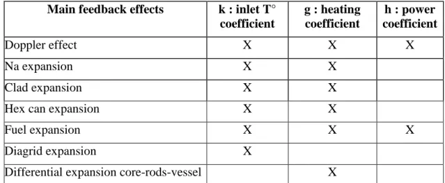
The three coefficients k, g and h include all basic reactivity feedback effects :
TABLE I: CONNECTION BETWEEN K,G,H AND BASIC REACTIVITY FEEDBACK EFFECTS
Main feedback effects k : inlet T°
coefficient g : heating coefficient h : power coefficient Doppler effect X X X Na expansion X X Clad expansion X X
Hex can expansion X X
Fuel expansion X X X
Diagrid expansion X
Differential expansion core-rods-vessel X
In a very simple way to fix some ideas, one can say that k is mainly representative of the diagrid expansion effect, g of the sodium and differential expansions and h of the Doppler effect. Obviously all coefficients are negative, if not, the reactor would be unstable.
The equation (2.1) becomes then
+ (2.4)
This fundamental equation can describe roughly the core behavior in any unprotected transient. In this paper, the focus is made on ULOF and ULOHS transients so no transient with external reactivity added is considered. We also made the hypothesis that the three coefficients are constant during the transient. This hypothesis is rather realistic for k and g but more questionable for h for consequent power variations as shown in the Phenix reactor2. We can also notice that the values of the coefficients are depending on a lot of parameters: beginning or end of fuel cycle, fuel linked to the clad or not, delayed expansion of control rods mechanisms… Moreover the approach is accurate when the asymptotic equilibrium is not so far from nominal state but not necessary for large transients as it is more a static than a dynamic method. Nevertheless, the results presented in this paper show a good predictability of the ULOF transient in comparison with reference calculations. All these limitations of the approach forbid to use it for safety demonstration but is relevant for safety trends assessment and core design comparisons, provided that the coefficients are calculated with the same hypothesis.
The equation (2.4) becomes then
(2.5)
Power is expressed with core temperatures and flow rate
2 The interest of the k,g,h approach is also the possibility to make some measurements during the life of the reactor. Experiments in Phenix showed a remarkable reproducibility of the k measurement and more discrepancy concerning g and h. Nevertheless the orders of magnitude of the coefficients were consistent during all lifetime of Phenix.
(2.6)
With (2.5) and (2.6), we can find the core outlet temperature To
(2.7)
The core outlet is a function of 8 parameters, 3 related to nominal state (Pn, Tin, ΔTn), 3
related to core and reactor design (k, g, h) and 2 representative of the transient scenario (α, Ti). At design stage, the objective is to minimize the core outlet temperature (avoid sodium
boiling) for a maximum of unprotected transient. The equation (2.7) can be use in two ways : - For a given design, assess the envelope transient scenario that the design
can cope with (considering a criteria on sodium boiling for example) ; - At design stage, optimize the k, g, h coefficients and eventually the
nominal state to cope with very severe unprotected transients.
The following parts are detailing how to use the equation (2.7) for simple theoretical transients (ULOF, ULOHS) and more generally for the ULOSSP transient.
2.2.ULOF transients
The ULOF case considered here is the simple theoretical case of ULOF : primary pumps are tripped at t=0s, without scram and without any failure in secondary or tertiary circuits. In this case, the hypothesis is to consider a constant core inlet temperature during the transient which is reasonable for the beginning of the transient.
(2.7) becomes
(2.8)
and the power is
(2.9)
As we will see later, is a representative coefficient of the capability of the core to decrease the power naturally.
We define the boiling margin3 by .
Thanks to this simple modelling (2.8), to avoid boiling, we must have (2.10)
A perfect core will avoid sodium boiling even for very low flow rate if (2.11)
Inversely, even the worst designed core for ULOF will avoid sodium boiling if the residual flow rate is higher than a minimal value of
.
For a given core, the residual flow rate necessary to avoid Na boiling is deduced from (2.10) :
with (2.12)
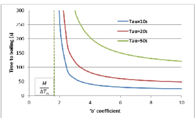
The following figure shows these relations between the ‘b’ coefficient and the core flow rate.
3 We consider that local boiling in ULOF can start when the mean sodium outlet temperature reach 820°C. It reflects the heterogeneity of flow rate distribution between sub-assemblies and inside each sub-assembly.
FIG. 1. Relation between the ‘b’ coefficient and the minimal flow rate to avoid sodium boiling
Typical values of this ‘b’ coefficient for large SFR cores are between 3 and 6 (see Table III), so the minimal residual flow rate to avoid sodium boiling in the ULOF transients are between 10 and 25%. The pony motors of the primary pumps must be designed to provide sufficient core flow rate in these situations. Since the natural convection flow rate order of magnitude is more between 2 and 5%, it shows the difficulty of avoiding sodium boiling for every ULOF scenario. Four ways are thus possible to improve the ULOF behavior of the core :
- Optimize the core design to reduce the value of ‘b’ ;
- Optimize the core and reactor design to increase the natural convection flow rate ;
- Increase the margin to boiling by decreasing sodium temperatures in nominal state ;
- Introduce in the design passive shutdown systems like hydraulic rods. Since the Na boiling can’t be avoided if the core flow rate is too low, we can evaluate the time of boiling and the power of the core at this moment.
The flow rate evolution during the ULOF transient can be written
with τ the halving
time of primary pumps in second.
(2.8) can be now written
and (2.9) becomes
.
We can deduce the estimated time of boiling :
(2.13)
The boiling time is directly proportional to the halving time of primary pumps. This formulation confirms (2.11) and (2.12) showing that boiling is always avoided if . The following figure shows the time of boiling vs the ‘b’ coefficient :
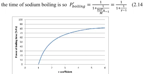
The core power at the time of sodium boiling is so
(2.14)
FIG. 3. Relation between the ‘ɤ’ coefficient and the power at boiling time
An important result is that the core power at boiling time doesn’t depend on the halving time of the primary pumps and can be related to a single coefficient ɤ. The faster the flow rate decreases, the faster the power decreases so the power reduction at the time of boiling is the same. In other words, more primary pumps inertia enables to delay the time of boiling but doesn’t really change the ULOF results concerning boundary conditions of the severe accident beginning. More halving time is only useful to provide some grace delay for the intervention of other feedback effects, as the diagrid expansion effect, as we will see later for the ULOSSP transient.
2.3.ULOHS transients
The ULOHS case considered here is the loss of secondary and tertiary circuits at t=0s, without scram and without safety Decay Heat Removal systems. In this theoretical scenario, the primary pumps are supposed to stay at their nominal speed. The sodium temperature at the core inlet is increasing slowly, inducing a power decrease mainly due to the diagrid expansion effect. The equilibrium state is reached when the neutronic power is equal to zero and the temperatures are homogeneous in the primary circuit.
This temperature can be calculated by using (2.5) with P’ and ΔT equal to zero.
The equilibrium temperature is then (2.15) We can also write with
This temperature should be minimized by design to prevent the reactor structures failure. A typical target value is to keep for example to avoid high creep damage.
Similarly to the ULOF case, the value of the ‘b’ coefficient should be minimized (g>>h) but also the value of φ (k >> g).
2.4.ULOSSP transients
In the ULOSSP case, we consider both an ULOF and an ULOHS scenario : loss of primary and secondary pumps at t=0s without scram.
The main equation (2.7) of the core outlet temperature evolution is
that we can also write :
= (2.16)
The first question concerns the behavior of the asymptotical core outlet temperature as a function of the inlet temperature, depending on the primary flow rate.
=0 pour (2.17)
This parameter αe represents the equilibrium flow rate for which the temperature at the outlet
of the core does not depend on the core inlet temperature. If the core flow rate is higher than the equilibrium flow rate αe, the core outlet temperature increase when the core inlet
temperature increases, but remains in all case under the equilibrium temperature θ. If the equilibrium flow rate αe is positive (k > g in absolute value), for low flow rate less than αe, the
core outlet temperature decreases when the inlet temperature increases. It means that the efficiency of the power reduction essentially by the diagrid expansion effect compensates the increase of the core inlet temperature.
(2.15) can be rewrite with αe :
(2.18)
This equilibrium point (θ, αe) is therefore a main parameter for the loss of flow rate transients
as shown in the following figure.
FIG. 5. Equilibrium temperatures in ULOSSP
Another interpretation of this figure is that for residual core flow rate less than αe, the ULOF
transient is more severe than the ULOSSP transient, and inversely for a flow rate higher than αe.
The core power is deduce from (2.6) and (2.16) :
(2.19)
For a simultaneous primary pumps trip without pony motors, we can write (2.16) and (2.19)
α residual flow rate (%Qn)
To core outlet temperature
θ αe Ti1 Ti2 Core inlet temperature Ti2 > Ti1
(2.20) (2.21)
These two general equations are used in §4.4 to compare some SFR core designs.
3. Discussion on safety trends estimators
As showed below in the theoretical part, the rough behavior of SFR cores during unprotected transients can be described with a very limited list of intrinsic parameters.
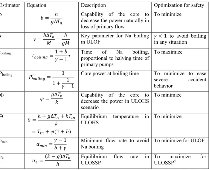
TABLE II: SYNTHESIS OF MAIN SAFETY ESTIMATORS
Estimator Equation Description Optimization for safety
b
Capability of the core to decrease the power naturally in loss of primary flow
To minimize
ɤ
Key parameter for Na boiling
in ULOF to avoid boiling in any situation tboiling
Time of Na boiling, proportional to halving time of primary pumps
To maximize
Pboiling
Core power at boiling time To minimize to ease severe accident behavior
Φ Capability of the core to
decrease the power in ULOHS scenario To minimize Θ Equilibrium temperature in ULOHS To minimize αmin
Minimum flow rate to avoid Na boiling
To minimize for ULOF
αe Equilibrium flow rate in
ULOSSP
To maximize for ULOSSP4
Reactivity feedback effects
We can assume from this table that the three coefficients have to be optimized to fulfill which is favorable for all estimators. Nevertheless, the ‘h’ coefficient, mostly
4 When considering only the theoretical ULOF with a constant core inlet temperature, this parameter is less relevant but could be minimize in order to have in any case. In this purpose, θ must be of course minimized (see Fig. 4 for further understanding).
composed by the Doppler effect, must not be too low for the natural behavior of the core during reactivity insertion transients (UTOP : Unprotected Transient Over Power).
We can also notice that for a given core power, large core designs may be favorable (especially for ULOSSP) because of the more important diagrid effect in comparison of other reactivity feedback effects. Finally, small power cores are also favorable for these unprotected transients because the effects of structures expansion are more efficient to reduce the core power in comparison of bigger power cores. In this case, ‘k’ and ‘g’ are higher, so the natural behavior is better for ULOF and ULOSSP.
Nominal state
Even if it may appear obvious, the safety trends estimators in the Table II show that the nominal state parameters have an influence on the capabilities of the core to undergo these unprotected transients. In fact, lower operating temperatures are quite favorable to gain some safety margins : [Ti ; To]=[400°C ; 550°C] is less easy than [Ti ; To]=[350°C ; 450°C].
Other parameters
The primary pumps halving time is only useful to delay the Na boiling in the ULOF transient. For the ULOSSP transient, this delay may be sufficient to have more time to decrease efficiently the power with the inlet temperature increase that induces diagrid expansion feedback.
4. Comparison of some SFR cores with these estimators 4.1.Validation of the simplified methodology
The methodology presented in this paper is quite powerful and simple to assess the safety characteristics of a given SFR. Nevertheless, the methodology is not rigorously accurate to perform calculations used in the safety demonstration. The utilization of the global reactivity feedbacks can be roughly validated thanks to the Phenix experience. A periodic test was performed regularly to estimate these coefficients. This test consists in three steps performed without activating the safety thresholds :
reactivity insertion with some control rods ;
core inlet temperature increase with a secondary flow rate decrease ; core heating increase with a primary flow rate decrease.
The order of magnitude of each step is below 10% in order to avoid the scram if some safety thresholds are reached. By measuring the stabilized parameters of the reactor between the three steps, the k, g, h coefficients can be deduced and then eventually recalculated with neutron codes. The very good reproducibility of the Phenix measurements demonstrates the applicability of the methodology and the set of hypothesis for small variations around the nominal state.
For bigger variations like the unprotected transients, the methodology suffers two limitations : the variation of these coefficients, calculated for nominal state, for large power and
temperatures variations. The ‘h’ coefficient is mainly concerned.
the simplification of the model does not take into account some dynamic effects like the structures expansion kinetics or the thermal inertias and the thermal heterogeneity within the plenums. So the method is more adapted to evaluate the asymptotic state than to calculate accurately all parameters during the transient.
The second point has a marginal impact as the following example will show. The ULOF transient has been studied for the ASTRID reactor since the beginning of the design stage in order to improve the natural behavior of the CFV core, both in prevention and mitigation of severe accidents [3]. Lot of ULOF calculations have been performed with CATHARE or SIMMER codes, showing a good reproducibility of the results, for example the time of boiling of ~40s with a primary pumps halving time of 10s [4]. This result can be found thanks to the equation (2.12) as we will see in the following part.
4.2.Comparison of safety estimators for different SFR
Four different cores are considered in this paper for a global comparison of their safety characteristics : the SuperPhenix core (SPX), the ASTRID core (CFV type), a core - named SFR1 in this paper - designed to promote better inherent safety5, a core - named SFR2 in this paper - designed to promote better performances without specific inherent safety considerations for these transients. Core SFR1 and SFR2 are not just theoretical cores but real pre-designed cores at CEA. The goal of the paper is not to describe core designs so we use only their k, g, h coefficients to compare their safety performances. The following table summarize the estimators with some common hypothesis for each core (Tin=400°C,
ΔTn=150°C, M=270°C, τ=10s). Last column indicates if the parameter has to be minimized or
maximized to favor the natural behavior.
TABLE III: COMPARISON OF SAFETY ESTIMATORS
SPX CFV SFR1 SFR2 Description
k pcm/°C 1,16 1,73 2 0,97 Inlet T° coefficient
g pcm/°C 0,55 0,73 0,77 0,54 Heating T° coefficient
h pcm/%Pn 4,54 4,29 3,93 4,89 Power coefficient
b 5,50 3,92 3,40 6,04 Capability of the core to
decrease the power in ULOF
ɤ 3,06 2,18 1,89 3,35 to avoid boiling in any
ULOF situation
tboiling °C 32 42 49 30 Time of Na boiling
Pboiling %Pn 67 54 47 70 Core power at boiling time
ϕ 71 63 58 84 Capability of the core to
decrease the power in ULOHS
θ °C 863 711 654 988 Equilibrium T° in ULOHS
αmin %Qn 24 19 17 25 Minimum flow rate to avoid
Na boiling
αe %Qn 20 35 47 13 Equilibrium flow rate in
ULOSSP These values can be situated with the abacus presented in figures 1 to 4.
5 This core is designed to optimize all neutronic feedbacks and especially the Doppler effect to cope with the UTOP transients
Discussion
Cores that are not optimized by design for these transients (SPX, SFR2) show a poor natural behavior, with Na boiling reached in ~30s at a power of ~70% Pn and an equilibrium T° for
ULOHS around 900°C. The CFV and SFR1 cores show a better natural behavior with a lower power at boiling time6 and a lower equilibrium T° in ULOHS between 650 and 700°C which may be acceptable even for a quite long period of time. Nevertheless, this exercise shows the difficulty to design a core that can cope with every unprotected transient, symbolized by ɤ<1. This ambitious objective may be achievable only with small cores where the ratio between reactivity feedbacks are more favorable (relatively to bigger power reactors, structures expansions feedbacks are more effective to decrease the power).
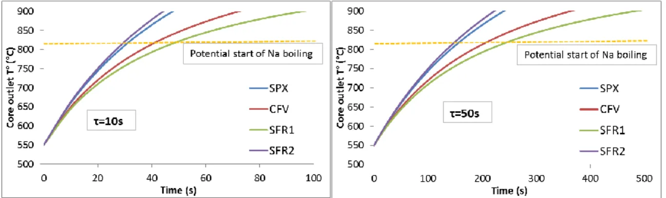
4.3.Comparison for ULOF transients
These figures illustrate the application of (2.8) for the four cores with a halving time of 10s and 50s. Core inlet temperature is supposed constant in this theoretical transient.
FIG. 6. Core outlet temperature for ULOF transient
As already discussed in the paper, we see that a higher halving time only delay the Na boiling but can’t avoid it (see §2.2). Nevertheless, we also see that the two inherently safe cores can bring twice more delay before boiling than classical cores. If the halving time of pumps is important, the hypothesis of taking the inlet temperature as a constant may be questionable. In this case, the ULOSSP case presented below may be more relevant for core behavior comparison.
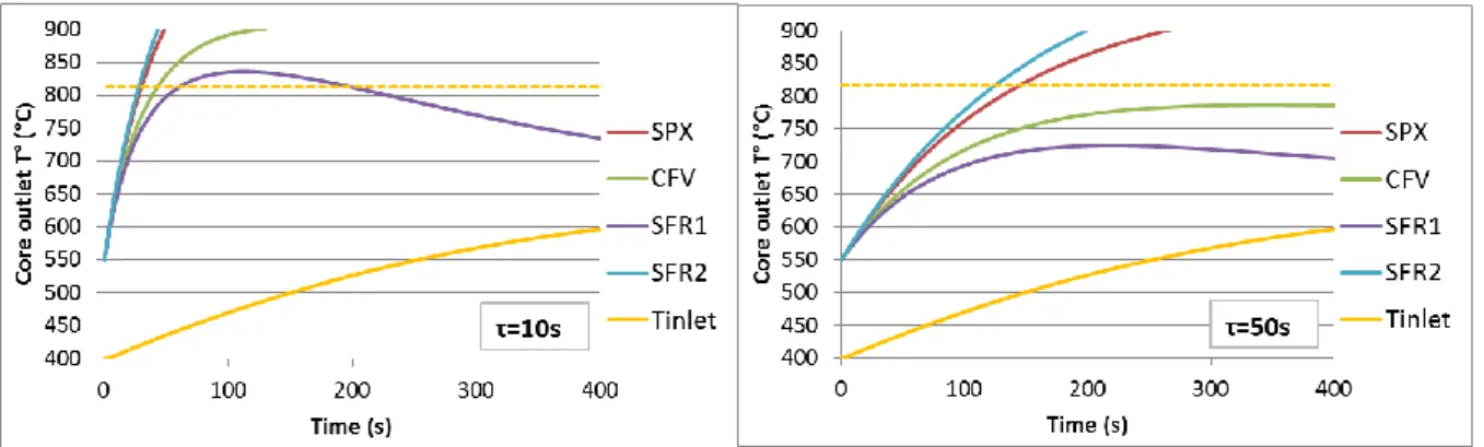
4.4.Comparison for ULOSSP transients
For the general ULOSSP case, we use (2.20) and (2.21) to illustrate the differences of natural behavior between the four cores. The variation of Tin is the same for all cores to simplify the
comparison. The hypothesis is based on a typical Tin evolution during an ULOSSP for
ASTRID case. Of course, this evolution is in reality dependent on the power of the reactor, of the thermal inertia and of the secondary circuits design.
6 This parameter is crucial for severe accident management. If the power reduction is very effective to a certain extent, it may open the way to stabilize Na boiling.
FIG. 7. Core outlet temperature for ULOSSP transient
In this case, global sodium boiling may be avoided for the SFR1 core with τ=10s. With τ=50s, sodium boiling is avoided for CFV and SFR1 cores.
FIG. 8. Power for ULOSSP transient
The power decreases faster when the flow rate decreases also faster. Nevertheless, the delay offered by a higher halving time allows decreasing the power more efficiently before boiling. This is a difference with the ULOF scenario where the power at boiling time is independent from the halving time.
5. Conclusion
The paper describes how to use the global reactivity feedback coefficients to assess simply the core behavior during the main unprotected transients. The analytical equations to evaluate the safety trends are provided. The paper shows that the ULOF and ULOHS inherent behavior can be roughly predicted thanks to a very limited list of estimators build essentially on the k, g, h coefficients. For example, we show that the power of the core when the sodium starts to boil during an ULOF does not depend on the primary pumps halving time. The ULOSSP scenario is more complex but can also be evaluated by this analytical approach, which is used to compare four different types of SFR core. The limitations of this approach are also discussed. Of course this approach is not dedicated to the safety demonstration but is consistent to assess the pre-conceptual safety issues. Furthermore, the k, g, h approach can be completed with some simplified thermal-hydraulic modelling (for decay heat removal or natural convection) and be use for other issues : reactivity transient, load following studies or passive shutdown systems specifications.
Acknowledgements
The authors wish to thank Marc Vanier, recently retired, for all the knowledge he shared with us and for inspiring this work on the k, g, h coefficients.
References
[1] D.C. WADE and Y.I. CHANG, “The Integral Fast Reactor Concept : Physics of Operation and Safety”, Nuclear Science and Engineering, vol.103, 1989
[2] N. STAUFF et al., "Methodology for Designing a Sodium-cooled Fast Reactor with Inherent Safety," Nuclear Technology, vol. 181, 2013
[3] MS. CHENAUD et al., "Status of the ASTRID core at the end of the pre-conceptual design phase 1", Nuclear Engineering and Technology , Vol. 45, 2013.
[4] A. BACHRATA et al., "Unprotected Loss of Flow simulation on ASTRID CFV-V3 reactor core” Proceedings of ICAPP 2015 – Nice, France