HAL Id: hal-01474239
https://hal.archives-ouvertes.fr/hal-01474239
Submitted on 15 Jun 2019
HAL is a multi-disciplinary open access
archive for the deposit and dissemination of
sci-entific research documents, whether they are
pub-lished or not. The documents may come from
teaching and research institutions in France or
abroad, or from public or private research centers.
L’archive ouverte pluridisciplinaire HAL, est
destinée au dépôt et à la diffusion de documents
scientifiques de niveau recherche, publiés ou non,
émanant des établissements d’enseignement et de
recherche français ou étrangers, des laboratoires
publics ou privés.
Studying fuel failure behavior with a micromechanical
approach
Coralie Esnoul, Rodrigue Largenton, Jean-Claude Michel, Bruno Michel,
Charles Pétry, Antoine Bouloré
To cite this version:
Coralie Esnoul, Rodrigue Largenton, Jean-Claude Michel, Bruno Michel, Charles Pétry, et al..
Study-ing fuel failure behavior with a micromechanical approach. Topfuel 2016, Sep 2016, Boise, United
States. pp.10 Pages. �hal-01474239�
Studying fuel failure behaviour with a micromechanical
approach
Coralie Esnoul,
1Rodrigue Largenton,
1Jean-Claude Michel,
2Bruno Michel,
3Charles Petry,
1and Antoine Bouloré
31EDF R&D – Site des Renardières – Département MMC, Avenue des Renardières, Morêt sur Loing, France 77818 2Laboratoire de Mécanique et d’Acoustique, Marseille Cedex 13, France 13453
3CEA Site de Cadarache DEN/CAD/DEC/SESC, Saint Paul Lez Durance Cedex, France 13105
+33 442257785 [email protected]
Abstract. Under Loss Of Coolant Accident (LOCA) conditions, the temperature evolution within the fuel pellets combined with a reduction of the cladding confinement can lead to fuel fragmentation. This phenomenon provides additional fission gas release, inducing a higher rod internal pressure and possibly an additional driving force to disperse the smallest fuel fragments out of the cladding when the cladding balloons and bursts. Experiments show that the pellets are fractured in many fragments, with size ranges varying from a few millimetres to a few microns. Usually the hypothesis used to explain fuel pellet fragmentation during transient, is grain cleavage induced by over pressurized fission gas bubbles, located at the grain boundary. This work focuses on the pellet rim, where bubbles density increases owing to a higher irradiation level. This area, called “High Burn-up Structure” (HBS), has a specific behaviour due to a microstructure reorganization composed of small grains about 100 nm compared to 10 μm for initial UO2 fuel. The aim of this study is to define a macroscopic fragmentation model based on a micro mechanical approach to have a better understanding of the fuel mechanical behaviour at lower scale: size and volume fraction of fragments. This paper introduces a stepwise micromechanical method: firstly, we detail how to model the HBS microstructure including pressurized porosities, based on experimental or numerical data and define a Representative Volume Element (RVE). Then we use 3D full field computations in order to determine crack snapshot. Elastic computations are performed to find the bubbles pressure level which is required to reach the cracks initiation threshold. Then nonlinear computations, using a failure local behavior law, are conducted to identify the failure snapshot. The latters will be used as an input data of the homogenization (“macroscopic”) model. This model is exposed in the last section. Keywords:over pressurized HBS bubbles, LOCA, failure model, crack mechanics, micro mechanical approach.
INTRODUCTION
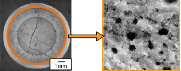
Under Loss Of Coolant Accident (LOCA), a leak appears in the primary coolant circuit: the water level in the nuclear vessel is decreasing. Fuel rods and by extension fuel pellets are not cooled anymore. This reaches to a rise of temperature into the pellet from 750 to 1570° K, constant along pellet radius, i.e. without thermal gradient through pellet thickness. In addition, it induces an additional fission gas release and thus, an increase of the internal rod pressure. Both actions of pressure and temperature, combined with a reduction of the cladding constraint, can lead to fuel fragmentation in addition to the one which usually appears during normal operation conditions. Experiment results show that pellets are fragmented in many pieces, with size ranging from few millimetres to few microns. Moreover, the smallest fragments may be dispersed out of the cladding when this one balloons and bursts under LOCA conditions. An example of resulting fragments and cladding burst found after a LOCA test in Studsvik device can be seen in figure 1 [1]. Studying the fuel crack behaviour should help to provide for fragments size after LOCA solicitations to ensure fuel confinement into the cladding and to understand how the fuel would relocate. One hypothesis used to explain fuel pellet fragmentation during a thermal transient is crack initiation and growth, induced by over pressurized bubbles located at the grain boundary. To investigate further this mechanism, we will define a fragmentation model based on a micro mechanical approach to complement the former experimental observations.
FIGURE 1.On the right,fragments extracted from the rod after a LOCA test and, on the left, cladding burst [1].
PROCESS
The micromechanical approach used is a multi-scale process which considers the fuel microstructure, and consists in: i) Gathering information to represent fuel microstructure, then ii) Achieving Full-Fields computations with Finite Element Method (FEM) to define a crack snapshot for UO2 fuel. iii) Establishing a homogenized failure model for the fuel pellet scale, to access to the fragment size. iv) Validating the failure model and implementing it into a thermo mechanical fuel rod performance code. Figure 2 summarizes all these steps which are detailed in the following.
FIGURE 2. Micromechanical approach scheme
i. Gather information to represent the fuel microstructure
First step is to consider UO2 morphological parameters in order to represent a numerical material, as close as possible from the one observed experimentally. Fuel pellets are composed of uranium dioxide and form a porous polycrystalline ceramic, whose microstructure is progressive, depending on irradiation level and considered radial position. In 1985 a typical microstructure, called “High Burn-up Structure” (HBS), is identified for the first time at the fuel pellet periphery, extracted from a high irradiated PWR fuel rod and held a lot of works attention [2, 3, 4, 5]. In normal operation this area could extend to 200µm for actual PWR fuel management. In fact, this microstructure is created by a material recrystallization which leads to subdivide 10µm original grains into smaller grains (about 0.1 to 1µm), due to low temperature < 1120°K (avoiding flaws annealing) and higher burn-up level at the fuel pellet rim. In this HBS area, gaseous fission products (mostly xenon and krypton) precipitated into bubbles, located at grain boundaries: in this work we assume that HBS bubbles are spherical. As HBS area is the most irradiated zone,
resulting fragments are likely susceptible to be ejected outside the cladding or could be relocated inside the cladding
Collect all needed information to represent a Representative Volume Elementary (RVE)
Develop a fracture model
HBS zone:
Fracture model behaviour:
- Local Law with damage threshold (B.Michel [7])
- Non local law behaviour with damage gradient (G.Francfort and J.-J. Marigo[9])
FIGURE 3. Radius position of the HBS zone in the pellet and HBS microstructure after its recrystallization. balloon, due to their outlying location. This phenomenon induces an additional heat-up and could amplify the balloon growth or even lead to the cladding burst. This is the reason why this work focuses on the HBS fragmentation. Figure 3 shows ceramographic examination of a high irradiated fuel pellet of UO2. The black spheres are inter granular HBS bubbles. These bubbles could represented up to 15% of material volumetric fraction, for a varying diametrical size between 0.2 and 4 µm. Their mean internal pressure is measured experimentally as being include between 70 to 200MPa.All information on bubbles collected, a 3D HBS representative material could be designed. Only a bubble size truncation is taken into account numerically, because of a scale effect. For example, we choose to model HBS bubbles whose diameter is included between 0.6 to 2.8µm, with a volumetric fraction of 10%. These bubbles are randomly drawn into a homogeneous 3D cubic matrix, using a Random Sequential Absorption scheme. This draw is achieved under solid sphere hypothesis: the merger among bubbles is not allowed. Moreover in this scheme, no bubble agglomeration is possible. A minimum distance of 12nm is set between two bubbles. This value is extracted from MEB observations found in the international program HBRP (1994-2002, CRIEPI and EDF) [5]. Thereupon, having a material design is not enough to perform Finite Element Methods (FEM) computations: a Representative Volume Elementary (RVE) must be defined.
ii. Achieving Full-Fields computations to define crack snapshots for UO
2fuel
The second step described on figure 2 intends to determine crack snapshots in the RVE with Full-Fields computations to supply the homogeneous model (step 3 on figure 2). All of these computations have been ruled with FEM.
Define a RVE for HBS fuel
A RVE must be large enough compared to heterogeneities dimensions in order to give a homogeneous behaviour at microscopic scale and small enough to be representative of an elementary volume from the macroscopic material. This size, called “characteristic length”, is chosen to define the RVE as a stationary material, which properties are not dependent from space. This could be checked by a covariance analysis tool, based on the distance between bubbles. In a heterogeneous material, covariance expresses the statistical probability that a point in a precise phase, will be in the same phase after the application of a translation vector ℎ⃗ , (𝑥, 𝑦, 𝑧), from the orthogonal basis (𝑥 , 𝑦 , 𝑧⃗⃗ ). The volume is stationary if covariance value converges to the bubbles volumetric fraction square. Figure 4 shows covariance results several for volume sizes from 5 to 20µm side. As we can see, 5µm size is diverging. 9µm is defined as the characteristic length, size of the smallest volume satisfying this hypothesis among all tested volumes. Figure 5 depicts the final draw for a 9µm large REV, later used in Full-Field computations (see part ii).
FIGURE 4. Covariance results on volumes from 5 to 20 µm large.
Volume half length (µm) 20µm 15µm 12µm 11µm 10µm 9µm 7µm 5µm 1mm Covariance
FIGURE 5. Example of a RSA draw of a HBS fuel
Material law behaviour
A material behaviour law is needed to investigate failure. To be consistent with LOCA thermal conditions, a brittle fracture is considered afterwards in the fuel pellet. All computations have been achieved with DDIF2 law, developed
by B.Michel and CEA [7]. This volumetric model is based on a continuum damage approach and uses a
linear softening law as a function of the fracture strain (fig. 6). Yield stress M, dissipated energy Gf and elastic
material properties E Young modulus and Poisson’s coefficient, are the only input data. This method could be compared to a cohesive zone approach; at the difference that crack opening C is replaced by fracture strain M. Consequently, in order to be consistent with a cohesive zone model, we consider that the crack is driven by the dissipated energy Gf, constant per unit surface. Therefore, the softening modulus Hf, describes by the Hooke law as:
M f
M H
. (1),
with Hf negative, should be a function of the element size. First step is to find the expression of Hf to ensure Gf constant.In a cohesive model:
C M f G . . 2 1 (2),
where crack opening id defined as : C M.L (3),
depending on L, element size. Replacing (1) and (3) in (2) gives the expression of the softening modulus to remain Gf
constant: L G H f M f 2 2 1 (4).
Figure 6 explains how the material could be damaged under loading, once the damage yield stress M exceeded. Specificity of the model is to take into account complex loading with partial or total crack closure. When gap is totally closed elastic properties are restored under a compressive stress state. Supposing that the damaged material is
FIGURE 6. Triangular linear law with damaged threshold for DDIF2 model.
reloaded, inelastic properties are derived from the maximum crack opening strain previously induced. In this study, only the first three steps are described, it means that unloading or compression after cracks closure are not activated as they are not representative of our LOCA thermal conditions. Model equations could be summarized as:
Volume size 9 µm Bubbles Volumetric fraction 10 % Bubbles diameters 0.6 – 2.8 µm Bubbles amount 85 Elements amount 206 615
Elements type Quadratic tetrahedrons
Geometry and mesh Periodic
Gf
fisHf
M 1: tensile loading with undamaged material. 2: micro cracking with linear stress softening. 3: macro crack opening for a fully damaged material.
(5) with
By notation, 𝑥̿ is a second order tensor, and is a fourth order tensor. This law is expressed in a damage basis 𝑛⃗ i, for each Gauss point, which assesses the local crack plane orientation. The first direction 𝑛⃗⃗⃗⃗ is determined by the direction 1
of the first principal stress which exceeds the threshold value M. The second direction 𝑛⃗⃗⃗⃗ is determined the same way 2
by using the second principal stress value which overtakes the threshold stress M. The third direction is then defined to have an orthogonal basis. For a monotone loading, as step 2, the equation of the function g is defined as following:
.
0:niMHf ifis
(6),
Introducing the Hooke law in equation (6) we can derive the crack opening strain as a solution of equation (7):
: :
.
0 fis i f M i fis tot H n E
(7),Further damage results are given as a percentage of critical crack strain
M
(expression deduced with (1)). In the following part, we see how the material respond to an internal bubbles pressure loading with this behavior.Computation results
Computations have been achieved on a RVE of 9µm identified previously, containing 10% of HBS bubbles, whose diameter varying between 0.6 to 2.8 µm. In order to avoid an indeterminacy of the static solution under Neumann boundary condition, the pressure loading is replaced by a strain control loading. We assume a thermal fictive expansion of the bubble gas, itself considered as a linear elastic material with a shear modulus much lower than the bulk modulus. This leads to a pure hydrostatic stress state in the gas. Therefore, the vector at the interface solid-gas is equivalent to a pressure loading. In this approach, bubbles are not empty: they need to be fully meshed and their material properties must be defined. Bubbles elastics parameters, Eb Young modulus and b Poisson coefficients are defined with Hooke relations:
𝜎 = 2µ𝜀 + 𝑡𝑟(𝜀)𝐼
µ𝑏 ≪ 𝜆𝑏 (8),
𝜎 ≈ −𝑝𝐼
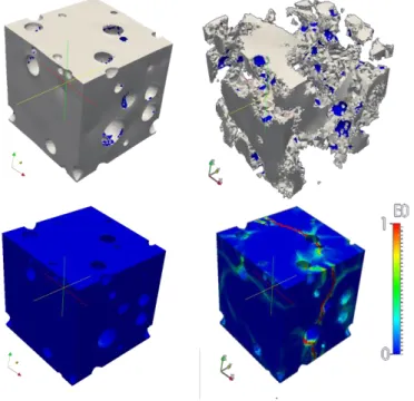
The first postulate means that there no shearing in bubbles. Bubbles are assumed to be filled with gaseous Xe/Kr products, so µb = 0. Second hypothesis is to assume b = UO2. Macroscopic UO2 elastic properties are given in literature: E, matrix Young modulus E = 200 GPa and v, matrix Poisson’s coefficient v = 0.3. We deduce from (8), b = 0.4996 and Eb = 200 MPa, while the first condition is possible only if Eb << E. Beside, two more model inputs have to be declared: Gf, dissipated energy and M, yields stress. Estimating these values is quite difficult since the dissipated energy and yield stress are respectively function of the irradiation level and of the study scale. Moreover, a lack of experimental tests subsists to determine fuel mechanical state at microscopic scale. Few experiments [8] try to access a value but grain boundaries properties is not known at high burn-up level. Indeed, gaseous fission products precipitated in either nanometric bubbles on the grain boundaries or inter-granular bubbles which could coalesce. The first bubbles species modifies boundaries grain chemistry whereas the other ones reduce the effective link surface between two grains. These combined effects tend to weaken grain boundaries. However, we choose the same yields stress than macroscopic scale yield stress, M = 100MPa, waiting for later experiments on micro sample (nano indentation tests [8]). Same issues remain for Gf which values is not measured precisely: as the DDIF2 model doesn’t take into account the aggravate effect on crack growth causes by pressure on crack lip, Gf has to be lower than the macroscopic value equals to 1-5 J/m². Finally, we opt for Gf = 0.1 J/m² to embody these phenomena. A numerical method called G-theta, which role is to determine dissipated energy at the crack front depending on the fault dimensions with 2D simulation, is planned to validate this value. Internal pressure bubbles increases from 0 to 300MPa and reproduces a LOCA thermal transient. All computation previously identified parameters are recalled in the table 1. Figure 7 shows results for 9µm HBS RVE with these input material properties. The first top RVEs illustrate
Stress
Elastic tensor
el Elastic strain
tot Total strain
fis Inelastic strain failureVector from the failure base, for i = 1 to 3
fragment formation where strains are multiplied per 500 to show separated pieces. Then the bottom ones display the crack snapshots at the end of the test, deduce from crack snapshots isovalues, normalized to critical strain 𝜀𝑀=
𝜎𝑀
𝐻𝑓≈
2. 10−3. It involves that, where snapshot field equals to 1, material is broken and crack is opened, if strain is inferior
to 1, material is damaged. Between theses values, material is damaged but not failed.
FIGURES 7. Fragment in formation and crack snapshots (normalised to critical strain values).
Crack opening could also be identified studying the internal bubble pressure. Figure 8 shows the mean bubble pressure level. A brutal depressurization is translated as a crossing crack among several bubbles: cracks growth is considered unstable. Then the mean pressure values increases. It means that not all bubbles are crossed by a crack and some continue to be loaded. Each brutal depressurization is interpreted as a new crack appearance which emptying fission gas in the bubbles.
Identification of crack snapshots are required in the following part to establish the homogeneous failure model. This model is detail in the following part even if it is in current development.
TABLE 1. Computation parameters for a 9µm tall HBS RVE.
Elements Quadratic Nodes Boundaries conditions Final mean pressure load
(MPa)
206 615 323 278 Periodic – free strain 210
Eb (MPa) b (-) Em (GPa) m (-) M (MPa) Gf (J/m²) 200 0.4996 200 0.3 100 0.1
FIGURE 8. Mean bubble pressure evolution. Depressurization is interpreted as a crack appearance in the he RVE.
iii. Establishing a “homogenized” failure threshold for the fuel pellet scale, able to access to
size of the fragments and their volumetric fraction.
Usually, a non local law is required to determine crack growth and be able to write a homogeneous model as it gives access to the total energy of the material. Moreover, its formulation is unable to emphasise size effects since no characteristic length-scale is involved in. Introducing size effect is possible with regularization techniques such integral or gradient approach. Their common point is the internal enhancement of the description of the damage distribution around a material point by giving additional information on its ‘neighbourhood’. A consequence is the necessary introduction of an additional material parameter, the length. Non-local damage models appear as an elliptic approximation of the variational fracture mechanics problem. The variational approach of brittle fracture recasts the evolution problem for the cracked state of a body as a minimality principle for an energy functional sum of the elastic energy and the energy dissipated to create the crack. Previously, crack snapshots were identified with a local law behaviour because that model was already implemented in the finite element code CASTEM [14]. Snapshot could be used as an input data of a homogeneous model based on a non local approach, proposed by Francfort and Marigo [9]. To be consistent, snapshot at local scale should be computed with this non local model too and compare with the local law results. This paper does not presented this part of the work on focuses on the description of the establishement of the homogeneous failure threshold based on a non local approach.
This variational approach, proposed by Francfort and Marigo [9], is written to the problem of interest here as: min
𝑢 ∈𝐶𝑡, 𝛼 ∈ 𝐷𝑡 ∫
𝑤𝑙(𝜀(𝑢), 𝛼, ∇𝛼)
𝑉−𝑇 𝑑𝑥 − 𝐿(𝑢) (9),
where 𝐶𝑡= {𝑢, 𝑢 = 𝜀̅(𝑡). 𝑥 + 𝑣, 𝑣 𝑝𝑒𝑟𝑖𝑜𝑑𝑖𝑐 𝑜𝑛 𝜕𝑉} denotes the set of cinematically admissible displacement fields
with the macroscopic strain 𝜀̅(𝑡) and the damage variable which verifies the non-reversibility 𝐷𝑡= {𝛼 ≥ 𝛼𝑡−∆𝑡}
with only increasing. V represents the total RVE volume, T the bubble volume. This expression (9) could approximate the minima of this energy functional through the minimization of a regularized functional that may be mechanically interpreted as the energy of a gradient damage model with an internal length [10]. Francfort and Marigo consider a gradient damage model in which the damage variable is a real number growing from 0 to 1: the material is undamaged when =0; fractured or fully damaged when =1. The behaviour of the material is characterized by
the state function 𝑤𝑙 which gives the energy density at each integration point. It depends on the local strain (u) (u and
(u) describing respectively the displacement and the linearized strain), the local damage value (x) and the local
gradient ∇𝛼 of the damage field at x. In the Francfort-Marigo model, wl, total energy, takes the following form:
𝑤𝑙 (𝜀(𝑢), 𝛼, ∇𝛼) = 1 2𝐴(𝛼): 𝜀(𝑢): 𝜀(𝑢) + 𝑤(𝛼) + 1 2𝑤1 𝑙 2∇𝛼 ∇𝛼 (10),
where w(), is the density of the energy dissipated by the material during a homogeneous damage process, w1 critical energy defined in the Francfort-Marigo law as:
𝑤(𝛼) = 𝑤1 𝛼 𝑤1= 𝑤(1) =
𝜎²𝑀
𝐸0 (11),
where E0, undamaged material Young modulus, M the threshold stress (same as the DDIF2 model input). l the characteristic model size identified with Gc, critical dissipated energy, known in the model as:
Time (-) Pressure
(MPa) When a crack crosses one or few bubbles, fission gas are
released: a depressurization appears. Time of first crack initiation First crack initiation pressure
𝐺𝑐= 2𝑙 ∫ √𝑤1𝑤(𝛼) 1
0 𝑑𝛼 (12),
A(),the rigidity of the material in the damage state , defined by:
𝐴(𝛼) = (1 − 𝛼)2𝐴0 (13).
In the problem of interest, the internal bubble pressure is the only loading. So the work of external force is written:
𝐿(𝑢) = ∫ − 𝑝. 𝑛 𝑢 𝑑𝑆𝜕𝑇 (14),
where p denotes the internal bubble pressure and n, the internal normal vector to 𝜕𝑇, bubbles surface. Sequel in the manner of the NTFA method [11], the following space-time decomposition is assumed:
𝛼(𝑥, 𝑡) = 𝑎(𝑡) 𝑚(𝑥) (15),
where a(t) is a time-dependent scalar variable and m(x), a scalar shape function containing crack mode information, both growing from 0 to 1. When 𝑎 ≅ 1, the crack mode m(x) is determined thanks to the former Full-Fields computations (see part ii. Computation results).
With (15), the potential energy can be written:
𝐸 = ∫𝑉−𝑇12 (1 − 𝑎𝑚)2 𝐴
0: 𝜀(𝑢): 𝜀(𝑢)𝑑𝑥 − 𝐿(𝑢) (16).
Thus the initial problem (9) becomes: min 𝑎 ∈ 𝐴𝑡 [ min 𝑢 ∈ 𝐶𝑡 (𝐸) + 𝑎𝑤1 ∫𝑉−𝑇𝑚 𝑑𝑥+ 1 2𝑤1𝑙 2𝑎2∫ ∇m ∇m dx 𝑉−𝑇 ] (17). 𝐴𝑡= {𝑎 ≥ 𝑎𝑡−∆𝑡}
Note that the displacement field u which minimizes the potential energy E is solution of the local problem: 𝑑𝑖𝑣 𝜎 = 0 𝑖𝑛 𝑉 − 𝑇 𝜎 = (1 − 𝑎𝑚)2 𝐴 0: 𝜀(𝑢) 𝑖𝑛 𝑉 − 𝑇 𝑃𝑎 (𝜀̅, 𝑝) 𝑢 = 𝜀̅. 𝑥 + 𝑣 𝑖𝑛 𝑉 − 𝑇 (18), 𝜎. 𝑛 = −𝑝. 𝑛 𝑜𝑛 𝜕𝑇 𝑣 𝑝𝑒𝑟𝑖𝑜𝑑𝑖𝑐, 𝜎. 𝑛 𝑎𝑛𝑡𝑖𝑝𝑒𝑟𝑖𝑜𝑑𝑖𝑐 𝑠𝑢𝑟 𝜕𝑉
where 𝜀̅and 𝑝 are respectively the macroscopic strainof the pellet and the average pressure in the HBS bubbles at time t.
Let G denote the energy release rate defined by:
𝐺 = − 𝜕𝐸
𝜕𝑎 ( 𝑢, 𝑎) (19).
Using the expression (16) of the potential energy, the variational property of u solution of (18) and the fact that 𝜕𝑢
𝜕𝑎 is
periodic on 𝜕𝑉, it can be shown that :
𝐺 = ∫𝑉−𝑇(1 − 𝑎𝑚)𝑚 𝐴0: 𝜀(𝑢): 𝜀(𝑢)𝑑𝑥 (20). Then by considering the minimum on a of (17), one obtains the damage condition:
𝐺 = − 𝜕𝐸
𝜕𝑎 ( 𝑢, 𝑎) = 𝑤1∫𝑉−𝑇𝑚 𝑑𝑥 + 𝑤1𝑙
2𝑎 ∫ ∇𝑚 ∇𝑚 𝑑𝑥
𝑉−𝑇 (21).
As we would like to establish a failure threshold and not a description of the damage evolution, only the case a(t)=1 (crack appearance) is considered. Replacing in (21), the failure threshold reads:
𝐺 = − 𝜕𝐸
𝜕𝑎 ( 𝑢1 , 1) = 𝑤1∫𝑉−𝑇𝑚 𝑑𝑥 + 𝑤1𝑙
2∫ ∇𝑚 ∇𝑚 𝑑𝑥
𝑉−𝑇 (22),
with u1 solution of P1, (Pa with a=1):
𝑑𝑖𝑣 𝜎 = 0 𝑖𝑛 𝑉 − 𝑇 𝜎 = (1 − 𝑚)2 𝐴 0: 𝜀(𝑢1) 𝑖𝑛 𝑉 − 𝑇 𝑃1 (𝜀̅, 𝑝) 𝑢1= 𝜀̅. 𝑥 + 𝑣 𝑖𝑛 𝑉 − 𝑇 (23), 𝜎. 𝑛 = −𝑝. 𝑛 𝑜𝑛 𝜕𝑇 𝑣 𝑝𝑒𝑟𝑖𝑜𝑑𝑖𝑐, 𝜎. 𝑛 𝑎𝑛𝑡𝑖𝑝𝑒𝑟𝑖𝑜𝑑𝑖𝑐 𝑠𝑢𝑟 𝜕𝑉
At this stage, we can notice that the local problem P1 is linear to the both variables 𝜀̅ and 𝑝. Under the superposition principle, u1 could be written as:
where 𝑢𝑖𝑗 and 𝑢̃ are respectively solutions of the local elastic problems P
1(ikk,0) and P1(0,1) with the convention 𝑖𝑖𝑗𝑘ℎ=
1
2 (𝛿𝑖𝑘𝛿𝑗ℎ+ 𝛿𝑖ℎ𝛿𝑗𝑘). Finally, introducing this linear decomposition (21) into the expression of the energy
release rate (20) with a=1, gives the quadratic form:
𝐺 (𝜀̅, 𝑝) = 𝐴𝑖𝑗𝑘𝑙 𝜀̅𝑖𝑗 𝜀̅𝑘𝑙+ 2 𝐵𝑖𝑗 𝜀̅𝑖𝑗 𝑝 + 𝐶 𝑝2 𝐴𝑖𝑗𝑘𝑙 = ∫ (1 − 𝑚) 𝑚 𝐴0 𝑣−𝑇 : 𝜀(𝑢𝑖𝑗) ∶ 𝜀(𝑢𝑘𝑙) 𝑑𝑥 𝐵𝑖𝑗 = ∫𝑣−𝑇(1 − 𝑚) 𝑚 𝐴0: 𝜀(𝑢𝑖𝑗) ∶ 𝜀(𝑢̃) 𝑑𝑥 (25). 𝐶 = ∫ (1 − 𝑚) 𝑚 𝐴0 𝑣−𝑇 : 𝜀(𝑢̃) ∶ 𝜀(𝑢̃) 𝑑𝑥
The three parameters Aijkl, Bij, and C are identified due to elementary loadings of strain or pressure: six Full-Fields computations with elementary strain loading (three extensions and three swellings in the three directions of space, no internal bubble pressure) and one Full-Field computation, loaded only with a unitary internal bubble pressure and imposing a null macroscopic strain.
Finally, this model is able to predict failure at macroscopic scale (pellet) by comparing the associated energy release rate G to a critical threshold Gmax, indicating if a crack happened or not, with the relation (23) checked in each integration point of the internal mechanical fuel rod code:
𝐺 ≤ 𝐺𝑚𝑎𝑥 (26),
Gmax given by:
𝐺𝑚𝑎𝑥= 𝑤1∫𝑉−𝑇𝑚 𝑑𝑥 + 𝑤1𝑙2 ∫𝑉−𝑇∇𝑚 ∇𝑚 𝑑𝑥 (27).
To determine time of failure and fragments size, different snapshots are taken into account. Currently, a cracks snapshot has been determined for the HBS microstructure for the LOCA loading and HBS microstructure (see part i), based on the first bubbles depressurization. This result should give information on the failure time during the transient. Another snapshot is identified at the end of the computation time, when all crack are created. This final state should be used in the homogenize threshold to describe how the material is carck at the local scale. This model should be then integrated intoa thermo mechanical fuel rod performance code (Alcyone/Caracas[12] and Cyrano3/Caracas[13]), to be validated at macroscopic scale this time (with results extracted from semi integral test i.e. performed in Halden or Studvisk device [1]. Afterward, the micromechanical method will be completed and be able to predict failure in the HBS fuel zone in LOCA conditions.
The present work actually ends at the step iii of the micromechanical method. Macroscopic model has been formulated and should be identified soon.
CONCLUSIONS
The aim of this paper is to introduce how use a micromechanical method to predict size and volumetric fraction of fragments, formed after a LOCA test. First, a RVE of the fuel pellet rim has been represented at the microscopic scale. Then a local damage law is used to study failure initiation and growth in the RVE, using FEM computation. This step is necessary to determine a scalar field, called crack snapshot, which represent the local damage state of the material. Then a homogenized model need to be define in order to transpose local results to the pellet scale. Crack snapshots are used as an input of this homogenized model. Its formulation has been developed with a view to being integrated in a thermal mechanical fuel rod code in the future, able to reproduce semi integral LOCA test and determine the size of the fragments and their volumetric fraction.
First computations with Full-Fields FEM method give promising results at local scale. Nevertheless, material parameters need to be refine as their experimental values are not perfectly defined yet, leaving an uncertainty in the model. Identification of the homogeneous model still remains to achieve. Besides, the non-local method, Francfort-Marigo law, should be carry out to redoing local calculations. Comparison between the two models should permit to define a benchmark, corroborating results obtains with local approach.
NOMENCLATURE
= Stress (MPa) mb = Matrix / Bubbles Poisson coefficient
= Yield stress Em / Eb = Matrix / Bubble Young modulus
Gf = Tenacity b = Matrix / Bubbles Lamé's first parameter
Hf = Softening modulus b = Matrix / Bubble Lamé's second parameter
L = Element size = Total strain
= Crack opening c = Total strain
ni = Vector from the failure basis, i = 1 to 3 el = Elastic strain
g = Damage functional in Inelastic strain failure
pi = Macroscopic bubble pressure 𝜀̅ = Macroscopic strain
V = Total volume T = Bubbles volume
A0 = Damage variable A() = Tensor of damaged material properties
E = Potential energy = Damage variable
l = Total energy m = Crack mode (damage spatial component)
1 = Critical energy a = Damage temporal component
G = Dissipated energy G max = Threshold energy
ACKNOWLEDGMENTS
This work is supported by EDF R&D – Ph.D CIFRE funding. CEA and LMA collaborators are gratefully acknowledged for fruitful discussions as well as their valuable help concerning this study.
REFERENCES
[1] “Post-Test Examination Results from Integral, High-Burnup, Fueled LOCA Tests at Studsvik Nuclear Laboratory”, NUREG-2160, (August 2013).
[2] S. Kashibe, K. Une and K. Nogita, “Formation and growth of intragranular fission gas bubbles in UO2 fuels with burnup of 6--83 GWd/t”, Journal of Nuclear Materials, 206, 1, pp. 22-34, 1993.
[3] K. Nogita, K. Une, “Irradiation-induced recrystallization in high burnup UO 2 fuel”, Journal of Nuclear Materials 226, 302-310, (1995).
[4] J. Noirot, L. Desgranges and J. Lamontagne, “Detailed characterisations of high burn-up structures in oxide fuels”, Journal of Nuclear Materials, 372, pp. 318-339, 2008.
[5] D. Baron, M. Kinoshita, P. Thevenin, R. Largenton, “ Discussion on HBS transformation in high burn-up fuels”; Nuclear Engineering and Technology, 41, 2, 199-214, (2009).
[6] R. Largenton, V. Blanc, P. Thevenin, D. Baron, “ Simulation and modeling the heterogeneous effects of the microstructure MOX fuels on their effective properties in nominal pressure water reactor conditions”, Advances in Science and Technology Vol. 73 (2010) pp 91-96 © Trans Tech Publications, Switzerland.
[7] B. Michel, J.Sercombe, G. Thouvenin, R. Chatelet, “3D fuel cracking modelling in pellet cladding mechanical interaction”, Engineering Fracture Mechanics 75, 3581-3598, 2008.
[8] J.-M.Gatt, J.Sercombe, I. Aubrun, J.-C. Ménard – “Experimental and numerical study of fracture mechanisms in UO2 nuclear fuel”, Engineering Failure Analysis, Col 47 B, pp 299-311, 2015.
[9] Francfort, G., Marigo, J.-J., 1998, “Revisiting brittle fracture as an energy minimization problem”, Journal of the Mechanics and Physics of Solids 46 (8), 1319-1342, 1998.
[10] Bourdin, B., Francfort, G., Marigo, J.-J., Numerical experiments in revisited brittle fracture, Journal of the Mechanics and Physics of Solids 48, 797-826 (2000).
[11] J.-C. Michel, P.Suquet, ‘Nonuniform Transforation Field Analysis’, International Journal of Solids and Structures 40, 6937-3955 (2003).
[12] G. Jomard, C. Struzik, A. Bouloré, P. Mailhé, V. Auret, R. Largenton, “CARACAS: An Industrial Model for the Description of Fission Gas Behavior in LWR-UO2 Fuel”, Proceedings of WRFPM 2014, Sendai, Paper No. 100154, Japan, Sep. 14-17, 2014. [13] R.Largenton, G. Thouvenin, “CYRANO3: the EDF Fuel Performance Code – Global overview and recent developments on
fission gas modelling”,Proceedings of WRFPM 2014, Sendai, Paper No. 100032, Japan, Sep. 14-17, 2014. [14] http://www-cast3m.cea.fr
![FIGURE 1. On the right, fragments extracted from the rod after a LOCA test and, on the left, cladding burst [1].](https://thumb-eu.123doks.com/thumbv2/123doknet/12911091.372454/3.918.252.672.99.269/figure-right-fragments-extracted-loca-test-cladding-burst.webp)