Distributed Curricular Goal Mapping
by
Stephanie Yu
Submitted to the Department of Electrical Engineering and Computer
Science
in partial fulfillment of the requirements for the degree of
Master of Engineering in Computer Science and Engineering
at the
MASSACHUSETTS INSTITUTE OF TECHNOLOGY
June 2015
c
○ Massachusetts Institute of Technology 2015. All rights reserved.
Author . . . .
Department of Electrical Engineering and Computer Science
May 21, 2015
Certified by . . . .
Steve Ward
Professor of Computer Science and Engineering
Thesis Supervisor
Accepted by . . . .
Albert Meyer
Chairman, Department Committee on Graduate Theses
Distributed Curricular Goal Mapping
by
Stephanie Yu
Submitted to the Department of Electrical Engineering and Computer Science on May 21, 2015, in partial fulfillment of the
requirements for the degree of
Master of Engineering in Computer Science and Engineering
Abstract
For this thesis, I implemented a tool that documents the equivalent of an API spec-ification for a course or other curriculum componenet in an educational curriculum. This API specification is the contractual relationship between each course and the surrounding curriculum. By decomposing the curriculum in a structural manner, we can more easily ensure consistency for courses and the goals they promise to teach across a curriculum. With such a structure, we can also begin to visualize these rela-tionships between courses, to better understand where what students learn will lead them in their time in academia. To do this, I created a visualization tool that takes advantage of the structure provided by the API specification and allows for the ob-servation and manipulation of these relationships. In addition to applying structure to a curriculum and visualizing the resulting relationships, I have also designed and implemented protocols that will allow these relationships to be shared and distributed across universities.
Thesis Supervisor: Steve Ward
Acknowledgments
I would not have been able to complete this thesis completely on my own. For this reason, I would like to thank my advisor, Steve Ward, for his unwavering support and continuous guidance through my time in developing this project and thesis. Without his insight and acting as a soundboard for my ideas, this project would not have been able to come this far.
I would also like to thank Hubert Pham for listening to me when I had a tangential idea and introducing me to Steve Ward and the original prototype this thesis is based on.
Contents
1 Introduction 11
1.1 Motivations for a curricular goal map . . . 12
1.2 Related Work . . . 13
1.3 Description of Curricular Goal Map (GMAP) . . . 16
1.4 API Specification . . . 17
1.4.1 Goal Properties . . . 17
1.4.2 Module Properties . . . 18
1.4.3 Module and Goal Relationships . . . 18
2 GMAP Language 23 2.1 Node Declaration . . . 23 2.2 Node Definitions . . . 24 2.2.1 Descriptive Properties . . . 24 2.2.2 Relational Properties . . . 24 2.2.3 Augmenting Properties . . . 25 2.3 Node Inclusion . . . 25 3 System Architecture 29 3.1 Parsing . . . 29 3.1.1 Conflict Resolution . . . 30 3.2 Evaluation . . . 31 3.2.1 Abstraction Mechanisms . . . 31
3.2.3 Collapsed Nodes . . . 34
3.3 Visualization Application . . . 35
3.3.1 d3 Graph . . . 36
3.3.2 Description Pane . . . 38
4 Distributed Curricular Goal Map 41 4.1 URLs as Globally Unique Identifiers . . . 41
4.1.1 References by URL . . . 42
4.2 Conflict Resolution . . . 43
4.2.1 Local vs. Remote conflicts - same name . . . 44
4.2.2 Remote conflicts - different includes . . . 44
4.2.3 Remote vs. Remote Conflicts - different servers . . . 44
4.2.4 Missing Definition - remote resolution . . . 44
4.3 Visualizing Remote Nodes . . . 45
List of Figures
1-1 Flow chart for EECS curriculum requirements . . . 14
1-2 Screenshot of MC3’s Concept Map Authoring Tool . . . 14
1-3 Early Prototype of Curricular Goal Map . . . 16
1-4 Example specification of the module named 6.01 with an example set of outcomes and prerequisites goals along with some of their subgoals. 19 1-5 Example relationship between modules and goals. 𝐴 and 𝐵 are mod-ules, and 𝐺 and 𝑆 are goals. . . 20
1-6 Example hierarchical relationship between modules and goals . . . 20
2-1 Example node declaration . . . 24
2-2 Sample GMAP file for 6.01 . . . 26
2-3 Different types of includes . . . 27
3-1 Example horizon . . . 33
3-2 Example horizon . . . 33
3-3 Different levels of detail showing . . . 35
3-4 Situations in which nodes will not reassign edges to each other upon collapsing . . . 36
3-5 Breadth First Search Algorithm with horizon and detail heuristics . . 37
3-6 Visualization UI . . . 38
3-7 Viewing the focus node 6.01 with a horizon of 3 and a detail of 0 . . . 39
3-8 The nodes in orange denote the explored nodes. In this case we have explored the nodes named 6.01, RLC Circuits, and 6.013 . . . 39
3-10 Source Code Editor . . . 40
4-1 Referencing includes by relative and absolute URLs, using a baseURL for relative URLs . . . 43 4-2 File 𝑓 𝑜𝑜𝐹 𝑖𝑙𝑒 on foo.com includes remote file 𝑏𝑎𝑟𝐹 𝑖𝑙𝑒 from bar.com.
The includes in 𝑏𝑎𝑟𝐹 𝑖𝑙𝑒 will include files on bar.com since that was the context that 𝑏𝑎𝑟𝐹 𝑖𝑙𝑒 is from. . . 43
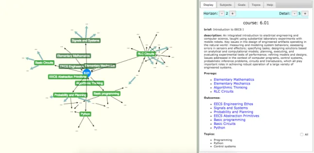
5-1 An example of how the visualization tool can be used to explore courses in the EECS department . . . 48
Chapter 1
Introduction
The Curricular Goal Map (GMAP) allows students and faculty alike to explore a curriculum in either minute or broad detail by breaking down the curriculum into a structured specification via a simple definition language. This specification follows a goal oriented model, using pedagogic goals to define the specification of curriculum components and develop a shared universe of goals. A web application that evaluates this shared universe illustrates the relationships between components of the curricu-lum, at both a high and low level. This web application proves versatile in its uses - it functions as a curriculum planning tool for faculty in providing a mechanism to structurally view and define a curriculum. This application also functions as a teaching and discovery tool for students, allowing them to visually walk through the curriculum they learn throughout their academic career and discovery exactly the set of skills they will learn. In addition, the application follows a protocol that allows the specification of the curriculum to be shared across multiple servers, letting edu-cators refer to components defined in different instances of GMAP and encouraging the sharing and evolution of the universe of goals.
Section 1.4 of this chapter describes the API specification used to break down a curriculum.
Chapter two describes the simple definition language used to define courses and goals.
Chapter four describes the design and protocol of the distributed aspect of the system.
Chapter five describes the current set of courses and goals, and discusses future work.
1.1
Motivations for a curricular goal map
MIT’s computer science curriculum teaches students methods for providing structure in their thinking and approach to engineering problems. However, we do not apply such a structure to the curriculum itself. Many curricula today consist of some con-crete set of prerequisite for courses, along with some vague, understood requirements that usually go undocumented. For example, an introductory course in computer sci-ence at MIT may be understood by students as requiring to know Python and basic programming beforehand, but not explicitly stated. These course grained modules make it difficult to accurately and holistically visualize the computer science curricu-lum in terms of the individual components a course is comprised of, as well as how those components might interact with other courses in the curriculum. By defining curriculum components in terms of an API specification, we can take a step toward organizing the curriculum in a consistent, structural manner.
Another motivation for documenting curricula according to a modular specifica-tion is directed at uncovering inconsistencies in course prerequisites and stabilizing content of critical courses taught by multiply faculty members. With a consistent language used to describe curricula, we can begin to discover components of curricula that are named similarly but differ in content, or universally named differently but similar in content.
We also recognize that a universal language alone to define courses is not suffi-cient - to make conflict discovery and inconsistencies float more easily to the surface, a visualization tool is needed to explore the relations between goals and courses. Plenty of tools already exist for students to explore courses and their prerequisites (CoursePicker [9], etc), but none of these tools are able to break down these courses
into their finer components and show exactly what components are related to what other courses.
Finally, with this structure and application, we desire to reach a broader audience than simply within a university or one department of a university - to encourage collaboration of educators across universities, we want to allow for a universal dis-tribution of a universe of goals. This would allow faculty across universities to have their own instance of GMAP and more easily discovery similarities and differences in curriculums as well as even share the possible overlaps.
1.2
Related Work
The idea of curriculum mapping is not new - there are many projects focused on structurally defining a curriculum according to some specification.
The most primitive and perhaps common example would be concept maps, preva-lent in nearly every collegiate department as a guide to students for what courses they should take in their academic career, such as those found in MIT’s Aeronautics and Astronautics and Electrical Engineering and Computer Science departments [12], [1]. These concept maps are usually general and broad, non-specific in what a student would actually learn, as illustrated in Figure 1-1.
The MIT Core Concept Catalog (MC3) [8] from the Office of Digital Learning takes concept maps one step further by introducing mechanisms that allow users to catalog the ideas and concepts behind a curriculum. These mechanisms also introduce the possibility of defining relationships between ideas. MC3 compiles this catalog as a concept map to be viewed in their interactive Concept Map Authoring Tool [3]; however, the concept map is huge and unwieldy (Figure 1-2). Since educators and faculty are given great latitude in defining their curriculum concepts, this leads to a sprawling graph that makes it hard to quickly and comprehensively understand the overall structure and direction of a curriculum.
There are also many cases made for describing components of a system with a structured specification. MIT’s Teaching and Learning Laboratory has developed a
Figure 1-1: Flow chart for EECS curriculum requirements
system to build an engineering curriculum map [14], but this map defines systems within a curriculum mathematically, and rigidly define learned concepts into three tiers. O2S [16] proposes a goal oriented programming model that considers the defin-ing of goals as an explicit semantic construct that describe higher level programmdefin-ing modules. They propose that goals are general and abstracted away from the rest of the system, allowing them to be invoked repeatedly. O2S is focused on using these goals for a more goal oriented programming semantic, viewing them as actions in-stead of descriptions; however, GMAP builds upon O2S’s core view that goals are a specification for higher level modules.
Similarly, the Planner [15] decomposes adaptive applications using Goals, which they use to identify specific implementation parts in addition to describing a specific problem. In addition to Goals, the Planner uses Techniques to describe alternative ways to satisfy Goals. These Techniques can also list prerequisite subgoals of Goals, as well as maintain a separation between them and the components that Techniques describe. The universe of Techniques is additive in nature; new Techniques can be added without disturbing the rest of the already defined Techniques. Although the Planner is also aimed at structured programming, these core features align closely with GMAP’s shared universe of goals and its use of goals and subgoals to describe higher level modules.
O2S and the Planner were not designed specifically around curriculum planning, but they posit a key idea of using goals as an abstract specification for higher level models, which GMAP uses and expands upon. Earlier examples of concept mapping prove lacking in structure and unwieldy in interface, making it hard to holistically understand the underlying nature of a curriculum.
With these issues in mind, MIT’s EECS ABET Team developed an early prototype of the Curricular Goal Map [6] that combines the graphing constructs of concept maps and the structure of goal oriented programming in a single interface that allows a user to graphically view a universe of goals (Figure 1-3). However, this early prototype was limited in its ability to share - it used a centralized database for its universe of goals, making it useful in a single department but difficult to actually share and collaborate
Figure 1-3: Early Prototype of Curricular Goal Map
on the planning and specification of curricula accomplished across a university or across several universities.
1.3
Description of Curricular Goal Map (GMAP)
GMAP consists of three main features:
1. Curriculum Decomposition via API Specification - The API specification uses a goal oriented model to describe the higher level modules of a curriculum. For now, we will assume these higher level modules are the individual courses or classes in a curriculum, but they can also be finer in resolution if need be, such as segments of a course, a lab, etc. Thus, it follows that the API specification has two main components, goals and modules, whose definitions can also establish relations with each other, which will be further discussed in 1.4.
2. GMAP Descriptive Language - The descriptive language is a simple lan-guage that uses terms defined in the API specification in key value pairs. This simple language enables the storage of goal and module definition in flat files, allowing faculty to quickly and easily iterate over defining their curriculum.
Similar to the Planner, this descriptive language allows for the definitions to be additive; adding more definitions will not disturb the existing universe of goals.
3. Visualization Application - The visualization application uses the d3 visu-alization JavaScript library [4] to display the modules and goals as nodes in a directed graph, using the relationship between modules and goals as edges. This allows the user to interact with the nodes, as well as explore the nodes and their relations. In addition to directly interacting with the curriculum modules and goals in a focused manner, the visualization application provides interfaces by directly editing and contributing to the universe of goals. The system archi-tecture behind the application also supports the distribution of this universe of goals across multiple servers, enabling the universe to grow and evolve.
1.4
API Specification
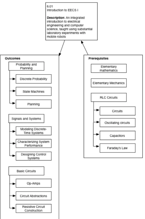
With an API specification for a curriculum, we establish an open ended universe of shared, pedagogic goals. A goal may represent a single lecture, a learning objective, or a subject taught in a course, serving as a specification for higher level modules. A module can consist of a set of goals, since goals; for example, a module representing the course 6.01 (Introduction to EECS I), could have goals such as Signals and Systems, Python, etc. These goals represent what a student would learn when taking this class, as well as what they should know before taking this class.
1.4.1
Goal Properties
Goals represent an abstract specification of higher level modules that are shared among these modules. A goal definition has several properties - a name, description, and specification. A goal specification describes what rubrics apply to the goal (such as specific abilities and skills), the topics the goal covers, and any subgoals the goal may have. These subgoals are a more granular breakdown of their parent goals. A goal’s subgoals may have their own subgoals, which may lead to their own
subgoals, etc., making the goal hierarchical in nature. For example, a goal named Basic Circuits can have subgoals of Circuit Abstractions, Op-Amps, and Resistive circuit construction. These subgoals are more granular components of the overarching goal Basic Circuits.
1.4.2
Module Properties
Currently, we view modules as representing course or classes in a curriculum. Each module has a name and description property, as well as a list of topics it may cover. In addition, it identifies two distinct sets of goals:
∙ Prerequisite goals - These goals reflect the assumptions made of incoming students, such as what skills and concepts they should know prior to the course.
∙ Outcome goals - These goals reflect what students should know after taking the course.
Figure 1-4 shows an example of a module representing the course 6.01 and some of the goals that describe it.
1.4.3
Module and Goal Relationships
Each goal need not be unique to a module it describes - the manner in which goals are defined allows them to be a general abstraction as a specification for modules. One goal can be the outcome and/or prerequisite of multiple modules, culminating in a universe of goals and modules.
Thus, given the nature of the specification of modules and goals, we can establish two different types of relationships between nodes:
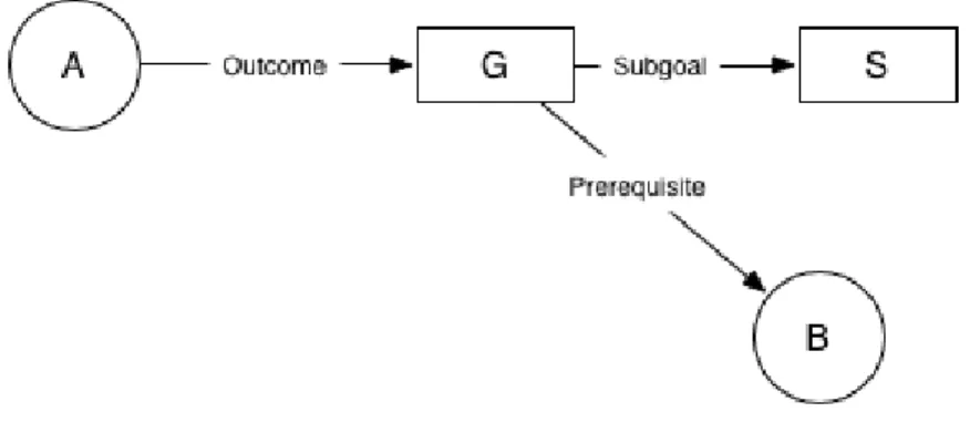
∙ Logical Relation - A logical relation between goals and modules is simply how they logically connect to each other: a goal may be related to a module via the fact that it is one of its prerequisites; alternatively, a goal may be related to another goal because it is a subgoal of the latter. For example, if module 𝐴 has an outcome goal 𝐺 which is a prerequisite to module 𝐵, we can broadly state
Figure 1-4: Example specification of the module named 6.01 with an example set of outcomes and prerequisites goals along with some of their subgoals.
Figure 1-5: Example relationship between modules and goals. 𝐴 and 𝐵 are modules, and 𝐺 and 𝑆 are goals.
A
goal
goal
goal
subgoal
Figure 1-6: Example hierarchical relationship between modules and goals
that module 𝐴 is a prerequisite of module 𝐵. Figure 1-5 shows an example of these possible relationships.
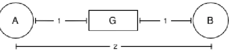
∙ Hierarchical Relation - A hierarchical relation reflects the different levels at which a curriculum can be viewed. Since we use sets of goals to specify a module, and a set of subgoals to specify a goal, we can view the relationship between nodes at a top level or a low level. Modules are considered top level, and goals that are prerequisites or outcomes of those modules are one level lower, etc. Figure 1-6 illustrates this concept.
comprehen-sible manner; however, even with the API specification providing structure, viewing all these relationships in a way the user can easily digest proves difficult. Even with just a few goals and subgoals, Figure 1-4 is already cluttered - these UI problems are solved in our visualization application.
Chapter 2
GMAP Language
To use the API specification to structurally represent a curriculum, we have designed a definition based language. The constructs of the language are simple - there are a set number of key words used to define the different components and each definition is written as a key: value pair. The language is written and saved to files with a
.gmap extension.
In this language, we refer to goals and modules collectively as nodes, since we view goals and modules as nodes on a directed graph in the visualization application. For now, let us assume that each goal has a unique name, and each module has a unique name, independent of each other. In other words, a goal and a module may have the same name, but they will be distinguished by whether they are a goal or module.
2.1
Node Declaration
Each node definition is contained within one contiguous block of text. The beginning of a node definition is denoted by a node declaration, which defines the type of node (module or goal) as well as the name of the node:
∙ module: 𝑚𝑜𝑑𝑢𝑙𝑒𝑁 𝑎𝑚𝑒 ∙ goal: 𝑔𝑜𝑎𝑙𝑁 𝑎𝑚𝑒
course: 6.01
goal: Signals and Systems
Figure 2-1: Example node declaration
A node definition completes when either the end of the file is reached or another node declaration is written. It is possible for a node definition to consist only of its node declaration.
2.2
Node Definitions
Following the node declaration are any number of lines describing the rest of the node definition. These can be defined in any order, so long as they follow a node declaration and are sequentially before any other node declaration. Figure 2-2 shows an example module declaration for 6.01.
2.2.1
Descriptive Properties
These properties textually describe the nodes; each node can have exactly one defi-nition for these properties.
∙ brief - The short description or canonical name of the goal or course (e.g. Introduction to EECS I for the course named 6.01).
∙ description - A longer description of the goal or course.
2.2.2
Relational Properties
These properties capture the direct relations a node can have with other goals; for example, listing subgoals of a goal. A node can have multiple definitions of these relational properties, denoted by a key: goalName pair on each line:
∙ outcome - A resulting goal from this node.
∙ subgoal - A subgoal for this goal; a specification for this goal that breaks it down into small parts.
2.2.3
Augmenting Properties
These properties represent additional relations that don’t necessarily warrant an en-tire goal or module, but are still useful in defining the node. A node can also have multiple of the these properties, denoted by a key: goalName pair on each line:
∙ topic: A topic belonging to the goal or course that might be something covered in the node, but not large enough to warrant a full node.
∙ rubric: A skill or lesson that this node teaches.
2.3
Node Inclusion
A curriculum can be comprised of any vast number of modules and goals; thus, it would be infeasible to maintain all these definitions in a single file. For this reason we use the include keyword to allow for more modularity in the GMAP files. The include keyword should be followed by a forward slash and then the name of the GMAP file. To generally include multiple files, the * notation can be used. A user can define nodes in multiple files, and then use the include keyword to add the definitions in those files to a single file. In addition, a single course or goal can be specified to load from a file. Figure 2-3 demonstrates these different inclusion techniques.
For ease of parsing, all includes must be defined at the beginning of each file. An include will be evaluated first before the definitions in the rest of the file are evaluated; an included file can also include other files, etc. The ability to include other files also introduces possibilities of conflicts between the nodes. The resolution of these conflicts are described in Section 3.1.1.
course: 6.01
brief: Introduction to EECS I
description: An integrated introduction to electrical engineering and computer science, taught using substantial laboratory experiments with mobile robots. Key issues in the design of engineered artifacts operating in the natural world: measuring and modeling system behaviors; assessing errors in sensors and effectors;
specifying tasks; designing solutions based on analytical and computational models;
planning, executing, and evaluating experimental tests of performance; refining models and designs. Issues addressed in the context of computer
programs, control systems, probabilistic inference problems, circuits and transducers, which all play important roles in achieving robust operation of a large variety of engineered systems.
outcome: EECS Engineering Ethos outcome: Signals and Systems
outcome: Probability and Planning outcome: EECS Abstraction Primitives outcome: Basic programming
prereq: Elementary Mathematics prereq: Elementary Mechanics prereq: Algorithmic Thinking prereq: RLC Circuits
outcome: Basic Circuits outcome: Python
# Add some top-level topics: topic: Programming
topic: Python
topic: Control systems topic: Inference
topic: Probability
topic: Sensors and effectors topic: Circuits and transducers
include: /6.01.gmap
# include all files in the directory include: /*.gmap
# include just one definition from a file import: /local.gmap#goalName
# definitions below
Chapter 3
System Architecture
To visualize the modules and their goals, I have designed a system that will consume the GMAP files and evaluate the relationships between nodes for display. This is done in three main steps: parsing, evaluation, and visualization. The entire system is implemented using NodeJS [11] for the server and using AngularJS [2] and d3 [4] for the frontend.
3.1
Parsing
As explained before, a GMAP file can specify any number of files to include. Thus, we stipulate that all GMAP files must be under a files/ folder in the root folder of the application, and the server serves GMAP files from this folder.
Since all definitions are stored in files, it would be inefficient and intractable to have the GMAP server constantly read and write to these files. For this reason, we use a MongoDB [10] database that serves as a cache for the nodes defined in the files. We also maintain a main.gmap file which functions as a manifest file that the system reads to determine what node definitions and files to include. This main.gmap file controls whether to include all files in the files/ directory or just a subset, depending on what administrators would like deisplayed. When the GMAP server first loads, it parses the main.gmap file to determine the set of nodes that need to be added to the Mongo database.
Parsing is accomplished in several steps.
1. Compilation - The main.gmap file is compiled to make sure that includes and node definitions are written in the correct order. While the server compiles main.gmap, it adds to a total list of definitions to be added to the database every time it encounters a new node definition.
2. Import Included Files - After compilation, the parser will go through the list of includes, if any, and obtain a list of nodes defined in each of the included files, recursively following includes if the included files also include other files.
3. Analyze - To make sure nodes are not referenced when no definition is loaded (e.g. declaring an outcome for a node when said outcome has not been included nor defined anywhere), we analyze the list of definitions and list of includes to make sure the nodes are defined properly, raising a warning or error when they are not. Any inconsistencies or errors encountered are flagged, and the erroneous node removed from the list of definitions.
4. Conflict Resolution - Once a list of nodes defined in the includes has been cor-rectly constructed, the parser will further evaluate the list of nodes constructed from compiling main.gmap and the list of nodes defined in the includes, re-solving any conflicts necessary as per the conflict resolution protocol outlined in Section 3.1.1.
5. Database Insertion - After the conflicts are resolved, the parser will have a complete list of nodes to be added to the database.
3.1.1
Conflict Resolution
There are three types of conflicts possible when defining nodes:
∙ Local vs. Local conflict - If a node is defined twice in a file, then the definition that comes sequentially later will be the one used.
∙ Local vs Included conflict - If file 𝐴 includes file 𝐵, and node 𝐺 is defined in both files 𝐴 and 𝐵, then the definition in file 𝐴 will take precedence over the definition in file 𝐵.
∙ Included vs Included conflict - If file 𝐴 includes two files, 𝐵 and 𝐶, and both files 𝐵 and 𝐶 define node 𝐺, then the system will not know which definition to use and therefore flag it as an error to the user.
∙ Missing Definition - If a node is referenced in main.gmap or one of its includes, but never defined, then the system will check if the database has a record of a node with that node name. If it does have a record, then that record is used for the node definition, and a warning will be shown to the user. If there are multiple records, then the first match returned will be used and a warning will be shown to the user. If there are no records of the referenced node, an error will be thrown, asking the user to defined the node.
3.2
Evaluation
To display the nodes, we use a directed graph, representing the modules and goals in the database as nodes and utilizing the relationship established between modules and goals as edges. A prerequisite of a module will have a directed edge from the prerequisite goal toward the module; conversely, an outcome of a module will have a directed edge from the module to the outcome goal. We also choose to focus the user’s attention on a single node, and display neighboring nodes at varying distances, which can be controlled by the user. We call this single node the focus node. Figure 1-5 is an example of how the relationships can be viewed as edges.
3.2.1
Abstraction Mechanisms
A curriculum can have a huge number of nodes in the form of goals and modules. As proven with large concept maps, showing a user a large sprawling graph is not entirely useful. To reduce the number of nodes we have to show to the user, we
introduce three different abstraction mechanisms, the first two representative of the relationships described in Section 1.4.3:
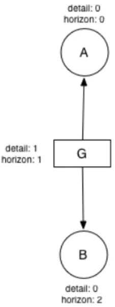
∙ Horizon - This is the logical distance between two nodes, reflecting the logical relationship between goals and modules: the number of edge traversals that separates them. For example, if module 𝐴 has an outcome 𝐺, then 𝐺 is a horizon distance of 1 from 𝐴. If 𝐺 is also a prerequisite of module 𝐵, then 𝐴 is a horizon distance of 2 from 𝐵. An example of these distances are illustrated in Figure 3-1.
∙ Detail - This is the depth, or level, at which a node sits, representing the hierarchical relationship between modules and goals. All modules are considered top level, and will therefore have a detail of 0. All outcomes and prerequisites of modules are considered directly contained under the module, and will have a detail of 1. Subgoals of those goals are considered contained under those goals, and will have a detail of 1 more than their parent goal, and so on. Figure 3-2 shows an example of nodes at different details.
∙ Bloom - Taxonomy of levels of understanding, which describes the educational complexity of a goal. A simplification of Bloom’s levels [13], we categorize levels of understanding into three levels:
(I) Familiarity - The student recalls or recognizes information, ideas, and principles a goal teaches
(II) Competency - The student is able to translate, comprehend, or interpret information based on prior learning.
(III) Mastery - The student has complete mastery over what the goal teaches, without needed direction or guidance.
These abstraction mechanisms are independent of and orthogonal to each other. We annotate the nodes with these mechanisms to control what a user should see. The detail of a node can be calculated independent of the horizon. Conversely, the horizon
Figure 3-1: Example horizon
depends on the focus node, since in the visualization application all nodes’ horizons are calculated as a logical distance away from the focus node. The bloom of the node is independently determined, depending on how the goal is actually specified.
3.2.2
Modified Breadth First Search
Given these abstraction mechanisms and a focus node, the visualization application shows nodes within a horizon ℎ and detail 𝑑 from the focus node (by default, ℎ = 1 and 𝑑 = 1). To determine what nodes are within ℎ and 𝑑 of the focus node, we perform a modified breadth first search starting from the focus node. Using the standard queue for breadth first search, for each node we pop from the head of the queue, we look at the neighbors of the node (a neighbor is determined to be any goal that is a prerequisite or outcome of a module, or is a subgoal of a goal). We then screen the unexplored neighbors based on their horizon and detail - if a neighbor’s horizon is within ℎ, then we proceed to check the neighbor’s detail. If the neighbor’s detail is within 𝑑, then we add the edge between the neighbor and the node to a list of edges and add the node to the queue. Since the edge is directed, we simply check whether the neighbor was a prerequisite or not to get the direction of the edge correct. Figure 3-5 contains some pseudo code for this modified breadth first search.
3.2.3
Collapsed Nodes
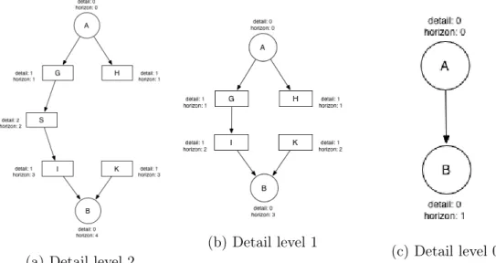
If the neighbor’s detail is not within 𝑑, we consider the node collapsed. A collapsed node hides nodes of higher detail under itself. For example, if a module 𝐴 has two outcome goals, 𝐵 and 𝐶, and 𝐴 is to be collapsed to a detail level of 0, then goals 𝐵 and 𝐶 would be hidden underneath 𝐴, since as outcomes nodes 𝐵 and 𝐶 have a detail level of 1. Figure 3-3 shows a focus node 𝐴 at different levels of detail 𝑑 and how its underlying goals are collapsed. When the nodes are collapsed, the horizon is updated to use the number of edge traversals between the collapsed nodes. In Figure 3-3b, the horizon between node 𝐴 and 𝐼 is now 2 instead of 3 since the node that was originally along the edge traversal, 𝑆, has been collapsed into 𝐺.
(a) Detail level 2
(b) Detail level 1
(c) Detail level 0
Figure 3-3: Different levels of detail showing
When collapsing nodes, we must pay particular attention to the direction of the edges when reassigning edges. For example, if both nodes 𝐴 and 𝐵 have goal 𝐺 as an outcome, when nodes 𝐴 and 𝐵 are collapsed, they will not point to each other despite having 𝐺 as a common neighbor, since that would imply either 𝐴 is an outcome of learning something in 𝐵 or vise versa, which is untrue. Similarly, if goal 𝐺 is a prerequisite for both nodes 𝐴 and 𝐵, when 𝐴 and 𝐵 are collapsed, they will not point to each other either. Figure 3-4 illustrates these examples.
When a node is collapsed because of a higher detail 𝑑, instead of searching the immediate neighbors during the breadth first search, we search the next visible neigh-bors. For example, in Figure 3-3b, at detail level 1 node 𝐺 is collapsed so that node 𝑆 is hidden. Therefore 𝐺’s next visible neighbor would be 𝐼 instead of 𝑆. The function 𝑔𝑒𝑡𝑉 𝑖𝑠𝑖𝑏𝑙𝑒𝑁 𝑒𝑖𝑔ℎ𝑏𝑜𝑟𝑠 in Figure 3-5 recursively searches for a collapsed node’s next visible neighbor, essentially the closest connected node with a low enough detail to be shown.
3.3
Visualization Application
With the nodes and edges properly calculated, we can now use d3’s force layout to display the nodes. The force layout helps position the nodes on the graph with some
(a) 𝐺 is an outcome of both 𝐴 and
𝐵 (b) 𝐺 is a prerequisite of both 𝐴 and 𝐵
Figure 3-4: Situations in which nodes will not reassign edges to each other upon collapsing
conditions such as giving each node a negative charge to repel each other; this helps arrange the nodes in a non-cluttered way while also letting the user manipulate them when exploring the graph. Figure 3-6 shows a screenshot of our UI application.
The visualization application is split into two main parts: the d3 graph, and the description pane.
3.3.1
d3 Graph
As explained before, displaying all the goals and the modules at once can be over-whelming to the user given how large curriculums can be. We choose one node as a focus node to center the user’s attention. From this focus node, we by default show all nodes that are a horizon of 1 and detail of 1 away from it. The graph has controls at the top to change what the horizon and detail are; the user can use these controls to show more or fewer nodes surrounding the focus node. Figure 3-7 shows an example of what the same graph in Figure 3-6 looks like at a different horizon and detail. In addition, the user can shift-click nodes to expand them individually,
func bfs(): nodes = []; edges = [];
queue = [focusNode]; visited = [focusNode]; while queue is not empty:
node = queue.pop(); nodes.add(node);
for neighbor in node.neighbors: if neighbor.horizon <= horizon: if neighbor.detail <= detail: if neighbor is prerequisite: edges.add(neighbor, node); else: edges.add(node, neighbor); if not neighbor in visited:
visited.add(neighbor); queue.push(neighbor); else:
for visibleNeighbor in getVisibleNeighbors(neighbor): if visibleNeighbor is prerequisite:
edges.add(visibleNeighbor, node); else:
edges.add(node, visibleNeighbor); if not visibleNeighbor in visited:
visited.add(visibleNeighbor); queue.push(visibleNeighbor);
func getVisibleNeighbors(node): visibleNeighbors = [];
for each neighbor in node.neighbors:
# must be both a prequisite and the neighbor a prerequisite # to be properly collapsed
if !(neighbor is prerequisite xor node is prerequisite): if neighbor.detail <= detail:
if not neighbor in visibleNeighbors: visibleNeighbors.add(neighbor); else:
visibleNeighbors.add(getVisibleNeighbors(neighbor));
Figure 3-6: Visualization UI
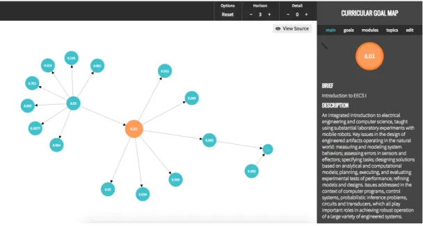
regardless of the specified horizon and detail. This mechanism gives the user more fine grained control over what they would like to see in the graph. As shown in Figure 3-8, the explored nodes are colored orange to show the user the path they are taking. The focus node can also be changed by double clicking the graph, effectively letting the user travel around the curriculum and its universe of goals.
3.3.2
Description Pane
To the right of the graph is a description pane that displays the properties of the focus node according to the API specification. The pane also has other tools that lets the user select different modules and goals as the focus node, in addition to adding additional nodes by using a form UI or uploading more GMAP files (Figure 3-9).
To reflect the ever changing nature of education, there is also an option to view the source GMAP file of the focus node (Figure 3-10). This enables users to directly edit the goals and modules and their definitions, as well as download the files to share with other users and collaborate on the specification defined for a curriculum. The opportunities for collaboration are further discussed in Chapter 4.
Figure 3-7: Viewing the focus node 6.01 with a horizon of 3 and a detail of 0
Figure 3-8: The nodes in orange denote the explored nodes. In this case we have explored the nodes named 6.01, RLC Circuits, and 6.013
(a) List of modules defined in curriculum
(b) List of goals defined in
curriculum (c) Upload tab
Figure 3-9: Different tabs of the description pane
Chapter 4
Distributed Curricular Goal Map
Academia thrives on the ability to share and collaborate, and GMAP has a distributed protocol to simulate this collaboration. With this protocol, a set of modules and goals defined in one GMAP server can be viewed and shared with another GMAP server. For example, suppose the MIT EECS department has one instance of a GMAP server, and the Math department has another instance. The EECS server may define some modules that have math goals as a prerequisite - instead of redefining goals that are already defined on the Math server, the EECS server can instead point to the goal on the Math server and include them as prerequisites in their local files, pulling the external nodes into their local visualizations. The effects of sharing goals and modules is not limited to just efficiency - different curriculums with similar courses can use this as an opportunity to discover similarities between curriculums, even across universities. A professor at MIT may notice their computer science class shares many of the same goals as a class at Stanford University; the possibilities are endless.
4.1
URLs as Globally Unique Identifiers
Implementing a distributed protocol raises challenges such as name conflicts for goals and modules. Though the discovery of these conflicts is part of the motivation behind GMAP, we still need a globally unique identifier so the system can distinguish between nodes despite how they are named across different GMAP instances. Since nodes
must have a locally unique name, we use a base URL, usually the URL of the GMAP server (e.g. http://example.com/files/), in combination with the name as a globally unique identifier. This allows for essentially two different namespaces in which to refer to nodes: a global namespace, and a local namespace. The global namespace uses the full URL (base URL plus node name) as the unique identifier. This namespace guarantees uniqueness across all servers, since in the local namespace of a GMAP instance the name of the node must be unique. This local name is also what we want to show the user, since it is more user friendly than a full URL. The global namespace is used when differentiating nodes from different servers, and the local namespace is used within a server, using the name to resolve nodes. When combining remote nodes from a GMAP server, their global identifier will be unique, but the display name may be the same. In these scenarios we will flag the difference to the user and leave a visual indication as to which is locally defined vs remotely defined, letting the user decide whether they want to reconsider renaming the nodes or reconsider including it in the first place.
4.1.1
References by URL
In addition to referencing includes by relative URL, includes can use absolute URLs to include a file or node:
import: /local.gmap
import: https://example.com/files/remote.gmap
The parser can easily differentiate between a relative and absolute URL. The server fetches the file from the server specified in the URL and parses it to be loaded into the local database. For a relative URL, it uses a specified 𝑏𝑎𝑠𝑒𝑈 𝑅𝐿 to resolve the file. Said 𝑏𝑎𝑠𝑒𝑈 𝑅𝐿 is located at the very top of each file; if it is not, the server assumes the namespace of the server as its 𝑏𝑎𝑠𝑒𝑈 𝑅𝐿. Thus each file should more or less be written in the format shown in Figure 4-1.
In Figure 4-1, local.gmap will be resolved to the URL 𝑏𝑎𝑠𝑒𝑈 𝑅𝐿 + /local.gmap, or http://localhost:3000/files/local.gmap. The main.gmap file therefore serves as a
# baseURL baseURL: http://localhost:3000/files # include statements include: /local.gmap include: https://example.com/files/remote.gmap # definitions below
Figure 4-1: Referencing includes by relative and absolute URLs, using a baseURL for relative URLs # barFile include: /test.gmap ... # fooFile include: http://bar.com/files/barFile.gmap ...
Figure 4-2: File 𝑓 𝑜𝑜𝐹 𝑖𝑙𝑒 on foo.com includes remote file 𝑏𝑎𝑟𝐹 𝑖𝑙𝑒 from bar.com. The includes in 𝑏𝑎𝑟𝐹 𝑖𝑙𝑒 will include files on bar.com since that was the context that 𝑏𝑎𝑟𝐹 𝑖𝑙𝑒 is from.
sort of manifest, containing the 𝑏𝑎𝑠𝑒𝑈 𝑅𝐿 it is operating under and a list of includes you would like to load. When the parser resolves the list of includes, it will use the absolute URL to make any remote requests. The external server will receive the request for a file and send back the appropriate file contents. When the local server receives the contents of the remote file, it will resolve any includes the remote file has within the context of the remote server. Figure 4-2 shows an example of this.
4.2
Conflict Resolution
In addition to the local conflicts described in Section 3.1.1, globally unique URLs also introduce their own set of conflicts.
4.2.1
Local vs. Remote conflicts - same name
If a node named 𝐺 is defined in a remote file 𝐴 and then imported into a local file 𝐵, but 𝐵 also defines a node named 𝐺, then the system will assume these two nodes are different and display both of them, with a flag to signify which is the locally defined node and which is the remote defined node. A warning will also be bubbled up to the user notifying them of the similarly-named nodes, so they can choose to resolve the conflict by renaming the nodes, changing the includes, etc., or leave them as they are.
4.2.2
Remote conflicts - different includes
If two nodes with the same name are included in two different includes that are both from the same remote server, the system will not know which node the user intends to use, and will flag it as a conflict in an error thrown to the user.
4.2.3
Remote vs. Remote Conflicts - different servers
If two nodes with the same name are included in two different includes that are both from different servers, the system will assume that these nodes are different and will not attempt to resolve the conflict, since the user may intend to include both. It will flag a warning to the user and display both nodes with an indication that both nodes are from different servers.
4.2.4
Missing Definition - remote resolution
If a node is mentioned but not defined, then the server will look into its local database for an existing definition. Since each node will have a context, based on what GMAP server the file that defines it is located on, the GMAP server will use this context to find the definition in the database.
4.3
Visualizing Remote Nodes
Nodes that are remotely defined do not display differently than local nodes, unless there is a conflict. There will be some indication of its origin in the description pane, but otherwise no change should be noticed by the user to provide a more seamless experience.
Viewing the source file of a remote focus node will not allow the user to edit, since it will be read only. However, the user will have the opportunity to download the re-mote source GMAP file and modify it on their own to be uploaded on their own local GMAP instance. This allows for branching of goal and module definitions, encourag-ing educators to build off each others view of a curriculum or multiple curriculums, increasing the opportunities to share and collaborate on creating a structure behind the curriculum instead of statically viewing and defining curriculum components.
Chapter 5
Future Work
Currently, we have compiled a database of nearly all the courses in the Electrical Engineering and Computer Science department at MIT. Each course has been broken down into sets of prerequisites and outcome goals. GMAP can be used to explore a path from basic courses taken in a student’s first year to more advanced courses, showing exactly what skills and concepts are learned along the way. Figure 5-1 shows an example exploration from the course 6.01 to the course 6.011 and its resulting goals.
Future work will be involved in GMAP’s installation into more departments in-stead of just the EECS department at MIT, as well as collaboration across universities or even across online curriculums such as the different universities partaking in edX. We recognize that the view of modules as simply courses will not be enough to satisfy all curriculums; thus, we can also explore finer-resolution modules, which would pave the way for establishing curricular goal maps to even Massive Online Open Courses (MOOCs) - imagine visualizing curricular goal maps for courses and concepts learned on Khan Academy [7] or edX [5], as well as how those maps may interact with the curriculum at MIT.
The API specification is also not limited to the definitions laid out in Chapter 2; there is much opportunity for it to grow and evolve to accommodate the complex nature of education. For example, more lax relationships between goals can be es-tablished, such as stating that goal 𝑆 may be a superset or subset of goal 𝐴. With
Figure 5-1: An example of how the visualization tool can be used to explore courses in the EECS department
the shared nature of GMAP, one curriculum may want to reference a goal in another curriculum, but the latter’s goal may not exactly be a prerequisite, subgoal, or out-come, but instead just simply be related - many other relations can be established to link goals across and within GMAPs.
Many other interactions are also possible with the visualization application. For students, when walking through the graph of nodes and expanding nodes to explore and view their composite goals, the UI could compile the set of goals learned when exploring a path, delivering a cohesive storyline for what a student may learn when taking a particular learning path. Editing is currently free and unrestricted to every-one for ease of development, but this can obviously be fine tuned for different levels of administration.
One aspect of sharing that can be expanded is duplication. Right now, to share a module or goal’s specification, one can download the original file the node was defined in and edit it oneself, to be shared and/or distributed to others. However, a possible extension of this sharing mechanism could be to branch off of that particular instance of GMAP itself, essentially creating local copies of the GMAP application for one’s own use and experimentation.
Education is constantly evolving and improving, and the nature of GMAP’s API specification allows it to grow and evolve with it.
Bibliography
[1] 6-3 degree flow chart. http://www.eecs.mit.edu/docs/ug/6-3.pdf. Accessed: 2015-5-18.
[2] Angularjs. https://angularjs.org/. Accessed: 2015-5-15.
[3] Concept map authoring tool. http://cmat.mit.edu/. Accessed: 2015-5-15.
[4] Data-driven documents. http://d3js.org/. Accessed: 2015-5-15.
[5] edx. https://www.edx.org/. Accessed: 2015-5-15.
[6] Eecs curricular goals. http://6004.mit.edu/gmap/. Accessed: 2015-5-15.
[7] Khan academy. https://www.khanacademy.org/. Accessed: 2015-5-15.
[8] Mit core concept catalog. http://mc3.mit.edu/home.html. Accessed: 2015-5-15.
[9] Mit course picker. https://picker.mit.edu/. Accessed: 2015-5-18.
[10] mongodb. https://www.mongodb.org/. Accessed: 2015-5-15.
[11] Node.js. https://nodejs.org/. Accessed: 2015-5-18.
[12] Sample academic pathways for course 16 students entering the major in the fall term of the sophomore year. http://web.mit.edu/aeroastro/ academics/undergraddocs/16-1-2-pathways-fallsoph.pdf. Ac-cessed: 2015-5-11.
[13] Taxonomy of Educational Objectives, Handbook I: The Cognitive Domain. David McKay Co Inc., New York, 1956.
[14] J. Rankin A. Bagiati L. Breslow J. French, D.Shah. Identifying and mapping piv-otal concepts and critical skills. In Concept Mapping a ’Freshmore’ Engineering Curriculum, September 2012.
[15] U. Saif G. Chau C. Terman S. Ward J. Paluska, H. Pham. Structured decom-position of adaptive applications. Technical report, MIT Computer Science and Artificial Intelligence Laboratory, LUMS Computer Science Department, 2008.
[16] J. Paluska J. Waterman C. Terman S. Ward U. Saif, H. Pham. A case for goal-oriented programming semantics. In UbiSys’03 - System Support for Ubiquitous Computing Workshop, 2003.