HAL Id: cea-00959498
https://hal-cea.archives-ouvertes.fr/cea-00959498
Submitted on 14 Mar 2014
HAL is a multi-disciplinary open access
archive for the deposit and dissemination of
sci-entific research documents, whether they are
pub-lished or not. The documents may come from
teaching and research institutions in France or
abroad, or from public or private research centers.
L’archive ouverte pluridisciplinaire HAL, est
destinée au dépôt et à la diffusion de documents
scientifiques de niveau recherche, publiés ou non,
émanant des établissements d’enseignement et de
recherche français ou étrangers, des laboratoires
publics ou privés.
Systems for Sodium-Cooled Fast Reactors: Fuel
Handling Route Optimization
Franck Dechelette, Franck Morin, Guy Laffont, Gilles Rodriguez, Emmanuel
Sanseigne, Sébastien Christin, Xavier Mognot, Aurélien Morcillo
To cite this version:
Franck Dechelette, Franck Morin, Guy Laffont, Gilles Rodriguez, Emmanuel Sanseigne, et al.. Study
and Evaluation of Innovative Fuel Handling Systems for Sodium-Cooled Fast Reactors: Fuel Handling
Route Optimization. Science and Technology of Nuclear Installations, Hindawi, 2014, Volume 2014,
Article ID 254913, 14 p. �10.1155/2014/254913�. �cea-00959498�
Research Article
Study and Evaluation of Innovative Fuel
Handling Systems for Sodium-Cooled Fast Reactors:
Fuel Handling Route Optimization
Franck Dechelette, Franck Morin, Guy Laffont, Gilles Rodriguez, Emmanuel Sanseigne,
Sébastien Christin, Xavier Mognot, and Aurélien Morcillo
Commissariat `a l’Energie Atomique et aux Energies Alternative (CEA), Centre de Cadarache, 13108 Saint Paul-Lez-Durance, France Correspondence should be addressed to Franck Dechelette; [email protected]
Received 19 June 2013; Accepted 3 December 2013; Published 11 February 2014 Academic Editor: Gianfranco Caruso
Copyright © 2014 Franck Dechelette et al. his is an open access article distributed under the Creative Commons Attribution License, which permits unrestricted use, distribution, and reproduction in any medium, provided the original work is properly cited.
he research for technological improvement and innovation in sodium-cooled fast reactor is a matter of concern in fuel handling systems in a view to perform a better load factor of the reactor thanks to a quicker fuelling/defueling process. An optimized fuel handling route will also limit its investment cost. In that ield, CEA has engaged some innovation study either of complete FHR or on the optimization of some speciic components. his paper presents the study of three SFR fuel handling route fully described and compared to a reference FHR option. In those three FHR, two use a gas corridor to transfer spent and fresh fuel assembly and the third uses two casks with a sodium pot to evacuate and load an assembly in parallel. All of them are designed for the ASTRID reactor (1500 MWth) but can be extrapolated to power reactors and are compatible with the mutualisation of one FHS coupled with two reactors. hese three concepts are then intercompared and evaluated with the reference FHR according to four criteria: performances, risk assessment, investment cost, and qualiication time. his analysis reveals that the “mixed way” FHR presents interesting solutions mainly in terms of design simplicity and time reduction. herefore its study will be pursued for ASTRID as an alternative option.
1. Introduction
In the framework of the French Act of June 28, 2006, about nuclear materials and waste management, a Generation IV and actinides incineration demonstration prototype is to be commissioned in the 2020 decade [1]. his prototype called ASTRID (Advanced Sodium Technological Reactor for Industrial Demonstration) sets out to demonstrate advances on an industrial scale by testing innovative options in areas earmarked for improvement (in particular safety, operability, and inspection and repair). R&D program led currently in support to the selection of ASTRID options, particularly in the following topics:
(i) core design with the objective of reducing the prob-ability of core meltdown and/or limiting the energy release during potential accidents, development of
innovative third shutdown system, and improvement in core monitoring;
(ii) improvement of decay heat removal (DHR) systems performances, with the development of an eicient system through the reactor vessel and the integra-tion of DHR heat exchangers in intermediate heat exchangers;
(iii) development of a strategy in support of the limitation of core melting consequences including the R&D in support to the development of the core catcher; (iv) development of innovative heat exchangers for a
gas-based energy conversion systems (ECS) as an alterna-tive to the classical steam cycle;
(v) development of innovative fuel handling systems (FHS).
Volume 2014, Article ID 254913, 14 pages http://dx.doi.org/10.1155/2014/254913
In terms of economy, Generation IV systems shall be competitive, for the same overall performance, compared to other sources of energy at the time they will be put into operation [2,3]. his means a lot of eforts with regard not only to investment costs but also to availability and operation costs. hese requirements impact fuel handling systems such as the following.
(i) Ater a learning period, the reactor must demonstrate a high load factor (e.g., up to 90%).
(ii) he investment cost of the prototype shall be min-imised, with technical options compatible with future commercial reactors deployment. his option is par-ticularly relevant in FHS selection which can inlu-ence several parts of the reactor block design: from the primary vessel diameter until the balance of plant and plant layout. he ratio of FHS (including external vessel storage tank (EVST), Casks, and civil engineering) in the total reactor investment cost is estimated from 15% to 20%.
From 2007 to 2009, R&D investigations in FHS aim to review design options [4, 5], experimental feedback from previous French sodium-cooled fast reactors (SFR) and international reactors [6–9], and to cross this review analysis with recent innovative options proposed by the scientiic community [10–12]. his work leads to a irst set of innovative preselected options [13] and to determining several axes of R&D development to pursue for ASTRID design options. In the ield of SFR fuel handling innovation, this paper aims to describe studies carried on since 2011 by CEA and in cooperation with COMEX Nucl´eaire and Bertin/CNIM as mechanical systems designers, and to characterise options regarding ASTRID criteria.
2. Scope of Work
Before deining the several routes chosen in the past and that could be investigated for the future, a review of the diferent options has been carried out using the fast reactor database and recent technological development in SFR design. he considered options concern fuel handling systems (under rotating plugs), transfer assemblies options between reactor vessel and external storage, and also, in the particular case of fuel handling through gas corridor, fuel handling in the EVST. he work performed is a characterisation of solutions, a performance review, and an analysis of the main advantages and drawbacks of the options compared to a so-called Starting Reference Solution (SRS) based upon well-known French SFR options or some option already envisaged in French project, that is, EFR reactor [14]. he main features of the SRS are described below.
(i) he primary in-vessel FHS is composed of two rotat-ing plugs (Superphenix and EFR option).
(ii) A direct lit charge machine is placed in the centre of the Above Core Structure (ACS) (EFR option). It is used for removal and insertion of core components belonging to the inner handling zone.
(iii) A ixed arm charge machine is placed on the large rotating plug (Phenix and EFR option). It is used for removal and insertion of core assemblies belonging to the outer handling zone. Furthermore, it forms the link between the load-unload station in the reactor and the direct lit charge machine using intermediate put-down/take-over positions at the inner core zone boundary.
(iv) he load-unload station in the reactor is an equip-ment supported by the reactor (Phenix and Super-phenix option).
(v) he fuel assembly evacuation is performed using a sodium pot for its permanent cooling (Phenix and Superphenix options).
(vi) A fuel handling cask leads to evacuate fuel assembly from the primary vessel to the in-sodium external vessel storage tank (Rapsodie and EFR option, but, was designed with no sodium pot in both cases, only gas cooling system and with low residual power spent fuel).
(vii) here is no rotor system (exchange new/spent fuel assembly), neither in the reactor vessel nor in the external storage.
he SRS option is represented in Figure1.
3. List of the Main Innovation Selected
Starting from the SRS route, several innovations were selected either on some speciic and targeted study on a single component or on a global approach on fuel handling route (FHR) from the primary vessel to the EVST. In a irst step, a large survey has been performed on innovative ideas without constraints or restrictions regarding maturity and cost level. hen, technological feasibility conclusion study is presented for each option, and a criteria grid analysis has been performed to highlight innovative options to persue for ASTRID. he following options have been investigated concerning the single route optimization:
(i) Above Core Structure (ACS) designed in two parts (one in the small rotating plug, SRP, and the other in the large rotating plug, LRP),
(ii) Pantograph Arm Machine associated with a slit ACS, (iii) design of the “Dual Location Rotor.”
(iv) design of the “Simultaneous Handling of two fuel assemblies.”
A second review [15] has been carried out and concerns speciic component optimization (SCO).
4. Fuel Handling Route Optimization:
Description of the ‘‘Mixed Way’’ Option
(Ramp and Transfer Lock, Gas Corridor)
4.1. Motivations. his option is investigated in order to mutualize the necessary equipment to twin nuclear plant
CC S PBT LRP SRP axis Core Motorized cask Sodium SRP LRP axis Direct lit machine Fixed ofset Fuel assembly arm
Figure 1: View of the fuel handling route called SRS.
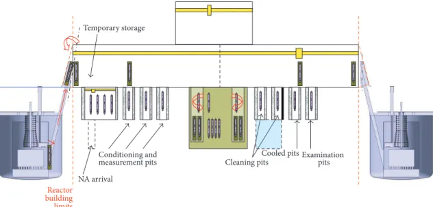
Reactor building limits Temporary storage Cooled pits Cleaning pits Conditioning and NA arrival Examination
measurement pits pits
Figure 2: View of the fuel handling route shared by two nuclear vessels.
units, for the development of an industrial leet of commercial SFR [16]; see Figure2. he standard transfer lock/charge and discharge ramp fuel assembly transfer system deployed on Phenix and Superphenix reactors can be used in a single-unit facility but cannot be integrally applied with a twin-unit option as the external storage twin-unit would be too close to each reactor vessel. Indeed, distance between reactor buildings would not be compatible with facility safety and operability requirements. herefore a “mixed way” including a transfer lock/ramp charge and discharge associated to a gas corridor has been developed to overcome the problem of reactor building proximity, with optimized simpliication of elementary operations, robustness, and availability.
he transfer lock/charge and discharge ramp solution, which is reliable and for which there is a signiicant feedback [7], presents the advantage of avoiding the displacement of a very massive cask inside and outside the reactor containment.
However, it is necessary to study the possible diiculties and key points raised by using a gas corridor mainly in terms of gas volume management and interaction with sodium, thermal behaviour of the assembly handled in this corridor during normal or degraded situation, and management of sodium drips along the fuel handling path.
4.2. Technical Characteristics. Technological solutions char-acteristics constituting this mixed way fuel handling route are described below.
Ramp and Fuel Transfer Pot in the Reactor Vessel. he solution features no real innovation in relation to the one developed for Phenix, mainly due to internal vessel geometry, that is, the implementation of a conical inner vessel. he angle of slope of the ramp is also standard, that is, around 17∘. he fastening of the fuel pot and its tilting feature are however innovative as
Figure 3: Sodium progressive tilting proposed.
the fuel pot needs to be transported from the primary vessel to the external storage unit with a separation of the casks. he fuel transfer pot has been designed to progressively tilt the pot using the speciic curvature of the rail supporting the pot (see Figure3). he fuel transfer pot can be lited up and down using a winch and a chain at the top of the rotating transfer lock.
he fuel transfer pot moving along the ramp comprises the following main components described in Figure4. Interface Rotating Transfer Lock. he fuel handling exit trans-fer lock is located on the reactor roof, supported by the con-crete loor with a valve to ensure isolation from the primary circuit at the argon cover gas plenum. his rotating transfer lock comprises a stainless steel envelope preventing the air from entering the fuel handling transfer lock (argon overpressure), as well as an external biological shielding (steel and lead) with a 500 mm thickness. he transfer lock itself slopes in relation to the loor by the half-angle of the ramp, that is, 8.5∘, to present the sodium pot-holding truck directly in a vertical position for transfer into the corridor. Each opposite side of the rotating part comprises two translation rails for the pot following on from the ramp as well as an associated secured hoist (emergency brake and additional descent device) and a chain reel. he rotating part has an ofset motor for access outside the biological protection and argon environment. he gas corridor provides the link to the fuel handling building. Figure 5 describes the main components of this rotating transfer lock.
Fuel Handling Gas Corridor. he gas corridor and its interface with the rotating transfer lock comprise an internal metal envelope (liner) ensuring corridor tightness and concrete biological protection (1 meter) to maintain a green zone outside in all circumstances. All the motors and actuators are placed outside the gas corridor. A camera viewing and image transport system enables the fuel handling process
3 4 2 1 5 6
Figure 4: Intravessel fuel transfer pot and ramp (1: massive common section, 2: gripper cradle, 3: embedded handles, 4: translation wheel, 5: holding counterwheel, and 6: chain fastening).
to be monitored. he ambient temperature and pressure levels are also monitored. A drainer collecting sodium drip is located at the corridor loor. A general ventilation system for the corridor evacuates the heat from the handled sodium pot. Two storage pits with active cooling system are set in the path of the gas corridor, between the positions of the reactor primary vessel on one side and of the EVST on the other. hese pits are used to return to a secure situation for cooling, provided that the residual power extraction system is suiciently eicient and passive for a period given.
he pot translation with horizontal transfer mechanisms takes place using a cable/wheel system driven by two syn-chronized motors, placed outside. Above the access to the external storage unit, a hoist lits up and down the pot holder to set down and pick up the sodium pot in the external storage vessel.
An isolation valve is located in the lower part of the access door to the external storage pit, and another one is located on the upper roof of the EVST. he pot-holder truck accessing the EVST moves along vertical rails to a low position in the vessel, to handle the assembly using the grabbing arm coupled to its rotating plug. With the geometry described in this study, it is possible to store approximately 340 assemblies for a main vessel diameter of 6.3 meters. he extrapolation to a twin commercial reactor can be obtained by symmetry of the gas corridor, since the pot transfer between the gas corridor horizontal transfer mechanism and the lit truck of the external storage unit can take place with arrival from the let or from the right.
Figure 6 shows a design of the mixed way FHR. he distance between the two axes of the reactor vessel and the EVST is approximately 23 m.
Primary Vessel Fuel Handling and Transfer. he solution selected is based upon two rotating plugs, a takeover position,
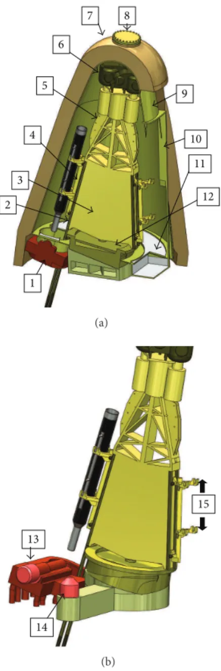
1 2 3 4 5 6 7 8 9 10 11 12 (a) 13 14 15 (b)
Figure 5: Detailed view of the ramp/gas corridor interface rotating part (1: primary circuit isolation valve, 2: ramp continuity rail, 3: inclined rotating part, 4: pot-holding truck in upper position, 5: chain guide and reel, 6: sealed secured hoist 7: biological shielding, 8: tight passage and motor access, 9: metallic envelope, 10: gas corridor link/exit interface, 11: dripping path and sodium recovery, 12: rotating part base, 13: isolation valve motorization unit, 14: rotating part motorization and drive unit, and 15: set-down and pick-up of the sodium pot).
and a ixed gripper arm on the large rotating plug (Figure6). he angle of the ramp is around 17∘.
Kinematic Transfer Applied to the Evacuation of an Irradiated Fuel Assembly. he fuel assembly discharge kinematic can be described in 9 major steps as presented in Figure7.
Figure 6: Vertical cross-section of the mixed way fuel handling route. 1 2 3 45 6 7 8 9
Figure 7: Kinematics for the evacuation of an irradiated assembly in sodium pot (1: assembly set-down in the pot, 2: pot moving up the ramp, 3: arrival at the upper stop of the rotating transfer lock, 4: rotation of the transfer lock in position, arrival of the corridor transfer mechanism in position, truck moving down the ramp, and pot set-down, 5: translation of the corridor transfer mechanism, 6: docking of pot holder associated with the temporary cooling pit and descent in the pit, 7: arrival in the EVST + pot liting using the pot holder up to detachment and disconnection, 8: pot-holder descent to the lower position of EVST, and 9: assembly fuel handling and set-down in storage unit using the ixed arm).
he cooling of the sodium pot containing a fuel assembly in the gas corridor (from the primary sodium exit to the entry into the EVST) must be studied according to the external design of the pot (pot designed to enhance heat convection with ins and forced ventilation of the transfer lock and corridor). he failure and blockage modes during displace-ments must also be investigated, especially with return to a safe cooling state to be ensured in any coniguration (in primary vessel, in external storage unit, or in temporary storage pit with passive cooling system), and fast enough to avoid fuel failure. Depending on the time to return to safe position, a residual power value per fuel assembly authorised for evacuation may be determined. he blockage risk of the transfer mechanism during translation in the corridor, loss of
power or drive motor failure, and the breaking of drive cables of the transfer mechanism must be studied and remedied using backed-up systems to return to a safe cooling position for the pot. A fuel handling rate may also be deined using this kinematic chain, according to the values usually taken for truck and horizontal transfer mechanism movement speeds, valve opening, pot dripping time, and so forth.
Internal Fuel Handling in the EVST. he solution reuses standard primary fuel handling elements, that is, a central rotating plug with an integrated ixed ofset arm. he overall height of the arm, with its mechanism, is limited to allow access to the lower part of the corridor. he design of the external storage unit takes into account the location of decay heat removal exchangers and the number and the location of storage positions (340 locations in this case). Residual power in the EVST is evacuated through three sodium/sodium heat exchangers placed at 90∘ around the vessel, accessible by a standard crane in the upper part of the building.
4.3. Technical Data for Option Qualiication. he main new points to be qualiied for this option are the pot thermal hydraulic with the hottest assembly in sodium; the manage-ment of sodium drips and aerosols in the inert atmosphere of the gas corridor and the rotating transfer lock; hoist mechanisms embedded in the rotating transfer lock; and demonstration of return to a safe state in case of transfer mechanism movement failure.
4.4. Option Performance Review
Economic Review. As a irst rough estimation, this solution seems less costly than the one corresponding to the SRS version, due to the absence of wide reactor containment opening and of a heavy cask transfer.
Safety Approach Review. As a irst study, this solution seems favourable with regard to earthquakes than a heavy cask circulating close to the reactor slab. he third containment barrier seems easier to maintain using a set of isolation valves rather than a wide opening of the reactor containment. As regards cooling the sodium pot containing the assembly being handled, the demonstration is more complex to realize than the cask, although it does not lead to a technical impossibility. But alternatively this analysis could lead to a decrease of the maximum residual power admitted for fuel handling which would impact the defueling strategy and consequently the load factor. Here relies the key point of this option.
ISIR Review. he instrumentation and monitoring of temper-ature parameters of the handled pot are slightly trickier to manage in a gas corridor than in a cask.
Operability Review. he ramp and transfer lock solution has been operational in Phenix and in Superphenix reactors. Furthermore, this fuel handling system using the gas corridor
has already been implemented and operated on the UK pro-totype fast reactor [17–20]. Feedback is therefore signiicant and good operability is estimated. Feedback handling time is optimized by minimizing and simplifying the movements and transfers of the entire kinematics chain, except for the takeover position. A short fuel handling transfer time might therefore be obtained, if a correct and continuous cooling of the assembly can be obtained.
Design Complexity Review. he ramp and transfer lock solu-tion is industrially known and its implementasolu-tion is not very sophisticated. he insertion of the gas corridor, the man-agement of its inert atmosphere, and the global kinematic chain make the design more complex compared to a cask-based displacement solution, but it does not pose any sig-niicant problems or incur any major extra costs in relation to the dimensioning of a reactor containment integrating a large opening for the cask transfer. he design complexity is therefore considered as medium compared to a cask-based solution.
Extrapolation to a Power Reactor. he solution can be twinned with a second nuclear island as previously explained.
5. Fuel Handling Route Optimization:
Description of the ‘‘Three Rotating Plugs,
Ramp and Gas Corridor’’ Option
5.1. Motivations. his concept is slightly similar to the previ-ous one. It has been studied in collaboration with Cea and Comex Nucl´eaire engineering nuclear company. his alter-native solution presents potential advantages: fuel handling was possible without takeover position in the primary vessel: no fuel handling arm, only vertical lits; minimisation of mechanisms in the vessel, two direct lit machines make fuel handling more lexible and restrict rotating plugs movements; no fastening and unfastening pot requirements because of a single transfer system use for both operations.
5.2. Technical Description of the Solution. he elements form-ing this fuel handlform-ing option are shown in Figure8. he steps for handling an irradiated assembly are as follows.
Fuel Handling in the Reactor Vessel. he system allows the assemblies to be transferred between the core and the horizontal transfer mechanism pot (HTMP). his equipment comprises the following subsystems: three rotating plugs and two direct lit machines. he rotating plugs can place the direct lit machines above any assembly of the core and above the horizontal transfer mechanism pot. he direct lit machines are used to lit an assembly up and down either in the core or in the horizontal transfer mechanism pot. Each direct lit machine is itted with a grabbing system locking an assembly during fuel handling. his system also provides an
Direct lit machines Transfer truck Transfer corridor Exit ramp External storage vessel 1 2 3 4 5 7 8 9 10 11 6
Figure 8: Steps of the three-rotating-plug solution in detail (1: the assembly is extracted from the core using one of the two direct lit machines, 2: the rotating plug movements position the direct lit machine above the horizontal transfer mechanism pot (HTMP), 3: the assembly is lited down into the HTMP, 4: the HTMP is tilted in the exit ramp, 5: the HTMP is driven back up the ramp to its position in the transfer truck, 6: the HTMP is tipped vertically into the transfer truck, 7: the transfer truck moves along the corridor to its position above the external storage vessel, 8: the HTMP is lited down vertically into the EVST, 9: the assembly is picked up by a fuel handling arm and removed from the HTMP, 10: the fuel handling arm positions the assembly above its storage location, and 11: the fuel handling arm sets the assembly down in its location).
Direct lit machine Center of the SRP Center of the CCS SRP CCS Center of the LRP (LRP not shown) Center of the CCS
Direct lit machine
2 plugs 3plugs (2 plugs + 1 rotating CCS)
Figure 9: Two plugs/three plugs kinematics comparison.
angular orientation of the assemblies being handled (rotation about a vertical axis).
he Number of Rotating Plugs. Two rotating plugs are suf-icient to reach any location in the core with direct lit machines. Using a rotary ACS supporting the direct lit machines limits the centre-to-centre distance between the large rotating plug and the small rotating plug, and conse-quently reduces the SRP size (Figure9). In order to reduce the diameter of the primary vessel, a third rotating plug was added.
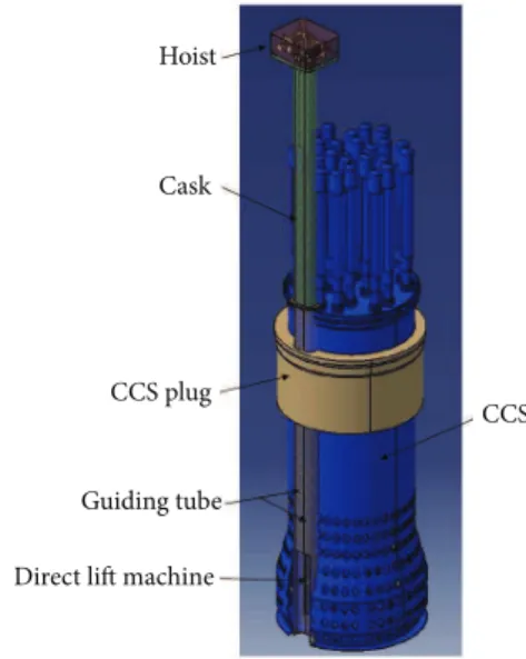
Direct Lit Machines. Direct lit machines are used to raise and lower the assemblies (Figure10). here are two rods to
Hoist
Cask
CCS plug
Guiding tube
Direct lit machine
CCS
Figure 10: Detail of the itted direct lit machines.
Guide tube Vertical drive system Guide ramp Access to external storage
Connecting rod for rotation movement Sodium pot
External storage
Figure 11: Horizontal transfer mechanism pot transfer system.
carry out operations in parallel inside the vessel. When the ACS comes into position above the sodium pot to set an irradiated assembly down, the sodium pot is loaded with a new assembly. he second direct lit machine is then used to extract the new from the sodium pot, to place the irradiated assembly carried by the irst direct lit machine.
Subassembly Transfer System. he horizontal transfer mech-anism (Figure 11) performs transfers between the reac-tor vessel (loading/unloading position) to the EVST. his
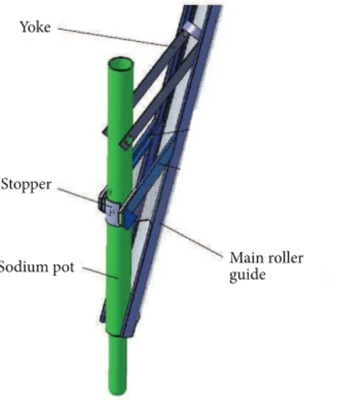
Yoke
Stopper
Sodium pot Main roller guide
Figure 12: View of the ramp system.
system comprises three sub-systems: equipment related to the reactor vessel (the extraction ramp and the reactor vessel shutof valve); the equipment related to the transfer truck (the horizontal transfer mechanism pot, the pot descent system) and its equipped truck; the equipment related to the EVST (support of the pot in the storage vessel, vertical ramp, and storage vessel shutof valve).
Reactor Vessel Entry/Exit System. his system comprises the equipment related to the reactor vessel: the shutof valve for the opening of the reactor slab, the horizontal transfer mechanism for pot guiding, and straightening ramp. A stop piece is positioned at the end of this ramp to keep the HTMP vertical (Figure12).
Transfer Subsystem. his sub-system comprises the HTMP with its shell and the manoeuvring systems for rais-ing/lowering, the mechanically welded structure forming the truck and the translation systems, the guiding tube housing the horizontal transfer mechanism pot and orientating it for introduction into the vessel, and the transfer corridor.
he transfer corridor is itted with two rails guiding the truck and sealed penetrations for manual intervention in the event of an incident on the drive system units positioned above the truck. he thickness of the corridor protects operators against radiation. he assemblies are cooled down by argon at a maximum temperature of 50∘C in the transfer corridor.
5.3. Technical Data for Option Qualiication. he main new points to be qualiied for this option are as follows: ther-mal hydraulic features of the pot (in sodium at handling temperature, irradiated, and new assembly), management of drips and behaviour in sodium aerosol atmosphere (mock-up representative of part of the corridor, outside biological
protection), and failure modes for the horizontal transfer mechanism displacement.
5.4. Option Performance Review
Economic Review. Compared to the SRS, it appears that fuel handling in the vessel is slightly more expensive due to the addition of the third plug and the minimal increase in the vessel diameter. In addition, the cost of a transfer corridor is to be compared to the cost of a cask and the cost of a reactor building extension during fuel handling, making the corridor solution less costly at irst approach. he gas corridor has signiicant larger volume than in the mixed way solution, inducing cost increase in terms of argon gas puriication, temperature, and pressure control equipment. Nevertheless this solution is considered in its overall to be less costly than the reference solution.
Safety Review. As regards safety, this solution seems equiva-lent to the “mixed way” solution.
ISIR Review. he number of items of equipment in the vessel is equivalent. However, inspection and repair in the transfer corridor may be an issue; a negative point is counted. Operability Review. On the whole, this solution is equivalent to the mixed solution or slightly better thanks to the removal of the takeover position in the vessel.
Design Complexity Review. he major diference lies between the cask and the transfer corridor. he management of luids, power, and information feedback is made more complex by adding a third rotating plug.
Extrapolation to a Power Reactor. his solution can be extra-polated to a future commercial reactor.
6. Description of the ‘‘Cask and Direct Fuel
Handling’’ Route
6.1. Motivations. his option has been studied in collab-oration with Bertin/CNIM mechanical systems designer company. his preliminary design presents the following advantages: no mechanism in the vessel during the reactor operation, optimized cooling of the assembly during the transfer using the cask (through integrated active cooling systems), and the transfer lock is ensuring continuity of the coninement of the reactor building. his solution can be considered as an innovative evolution of the SRS option. 6.2. Technical Description of the Solution. he equipment required for the primary fuel handling is described as Figure13: an LRP installed on the slab of the reactor vessel, an SRP installed on the LRP, a sealed penetration installed on the SRP itted with a shielded valve sealing the penetration during fuel handling campaigns, a direct lit machine centred on the ACS, two fuel handling casks, roller rails for cask transfer, a transfer lock between the fuel handling building and
SRP LRP Cask Cask Roller rails Drower airlock
Figure 13: Main components of the Bertin/CNIM fuel handling route.
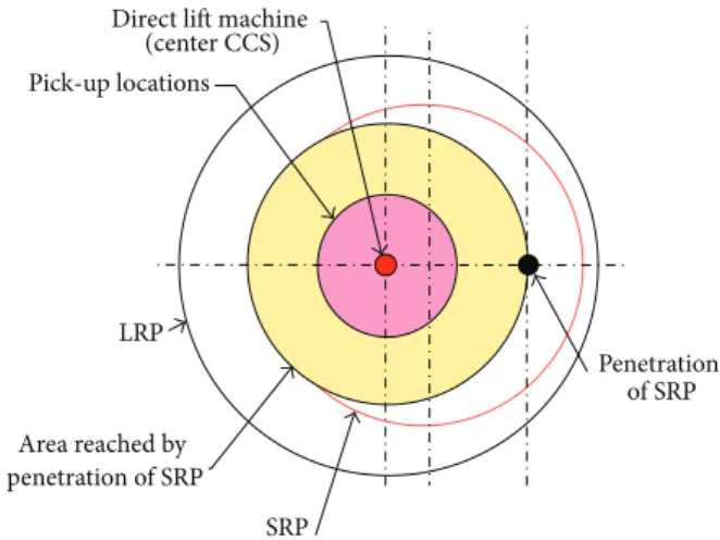
Direct lit machine (center CCS) Pick-up locations Penetration of SRP SRP Area reached by penetration of SRP LRP
Figure 14: Retention of the direct lit machine at the centre of the ACS.
the reactor building, a rotating plug on the slab of the EVST, a fuel handling arm installed on the rotating plug of the storage vessel, and a pick-up station integrated into the EVST. Fuel Handling in the Vessel. he combined rotations of the two rotating plugs provide access to all the core fuel assemblies. To minimise the impact on the diameter of the primary vessel, the direct lit machine installed at the centre of the ACS is kept (Figure14).
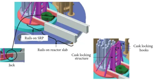
Structures Involved in Cask Holding and Displacement. he rolling rails allow the truck to take position on the SRP. hey are in two parts: a irst ixed part on the reactor slab and a second mobile part linked to the SRP. Accordingly, these rails will follow the SRP when rotating. Two electrically controlled screw jacks will support the rails when the truck passes (Figure15).
A cask support structure, integral with the SRP, locks the cask when the truck is removed. he cask/structure link is
ensured by two locking hooks and holds the cask in the event of an earthquake.
Transfer Cask. It is used to extract a spent fuel element from the reactor vessel, transfer it and place it in the EVST, and extract a new fuel element from the EVST. he cask comprises the following subsystems: a cask casing, a sodium pot (where irradiated assembly is cooled), a fuel grabbing tube, and a cask cooling system (Figure16).
he lower part of the pot comprises a plug valve sealing the pot. his valve is controlled by a rack located at the pot guiding tube. When the pot descends into the vessel, the toothed shat of the valve engages in the rack and rotates the pot. he bearings of the journals of the plug valve are specially designed to be disengageable from the top of the pot to open the valve even in the event of seizure (Figure17).
In this cask the spent fuel must be continuously cooled. he cooling system architecture is done by argon lowing in a circuit in the cask and cooled down by the units outside the cask by blowers (set with two redundant cooling units). he cooling units are installed on a loor integrated into the cask with mechanical uncoupling.
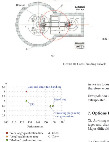
Airlock. here is an airlock between the reactor building and the fuel handling building to transfer simultaneously two casks through a fuel handling path (Figure 18). he airlock comprises two doors with inlatable seals. In closed or open position, the doors are automatically locked by motors. A control unit balances the pressures in the airlock when opening towards one of the buildings. he fuel handling path is installed inside the airlock. It features two running rail locations, the irst one to support a cask and the second one to allow the cask to go from one building to the other. 6.3. Technical Data for Option Qualiication. he two main points to qualify are
(i) the cask featuring direct extraction with its sodium pot with opening in the lower part:
(a) the plug valve qualiication: operation in air, sodium, and temperature environments, be-haviour from aerosol deposits, ageing of the bearings and the seals, remote controller, and degraded mode operation,
(b) the guiding tube system qualiication with inte-grated grab,
(c) the truck behaviour when loaded,
(d) the isolation valves of the reactor vessel qualii-cation (in sodium aerosols);
(ii) the reactor building qualiication exit airlock. 6.4. Option Performance Review
Economic Review. his option is considered more costly than the SRS solution, mainly due to the need for two casks working in parallel to obtain a correct fuel handling time, the
Rails on SRP
Rails on reactor slab
Jack
Cask locking hooks Cask locking
structure
Figure 15: Details of the running rails and cask holding structure.
Cooling device
Isolation valve Sodium pot Cask casing
Hoist
Fuel tube gripping F C C 13040 5791 G ∅9 50
Figure 16: Overview of the transfer cask.
Disengeageable bearing
Bearings of the journals of the plug valve
Gear for valve rotation
Double joint sealing with inter-joint argon test
RB Reactor External storage (a) Slide Sealed doors Rolling track (b)
Figure 18: Cross-building airlock.
100 110 120 130 140 150 160 170 1 0.5 1.5 2 2.5 3 SRS 3.5 Performances Ri sk s
“Medium” qualiication time “Long” qualiication time “Very long” qualiication time
3 rotating plugs, ramp and gas corridor Cask and direct fuel handling
Mixed way
Cost>
Cost=
Figure 19: Graphical representation of the assessment of solutions.
increased primary vessel diameter, and the extra cost related to complex mechanisms integrated into the cask.
Safety Review. his solution is positive as regards the cooling of the assembly when transferred by the cask but negative due to the complexity of mechanism incorporated into the cask and by the cask being rotated above the reactor core. herefore, the solution does not seem favourable.
ISIR Review. he absence of any mechanism in the reactor vessel makes these operations easier. he solution is therefore positive.
Operability Review. he solution is better than the SRS due to two casks working in parallel.
Design Complexity Review. he mechanism incorporated into the cask is complex compared to SRS. All the technical
issues are focused into one single component: the cask, which therefore accumulates all technological constraints.
Extrapolation to a Power Reactor. he system can be fully extrapolated.
7. Options Review
7.1. Advantages/Drawbacks and Difficult Points. he advan-tages and drawbacks of each solution are listed in Table 1. Major diiculties are marked in bold.
7.2. Quantiication and Comparison of Each Option
Criteria Grid. Based on the technical elements above, criteria have been generated in order to evaluate and to determine the maturity level of the solutions. A total number of 70 criteria have been analysed to compare each solution in terms of performance and complexity of the design, cost, and availability in-service inspection, risk, and safety. Table2is providing a summary of the analysis carried out that focused on cost and risk aspects.
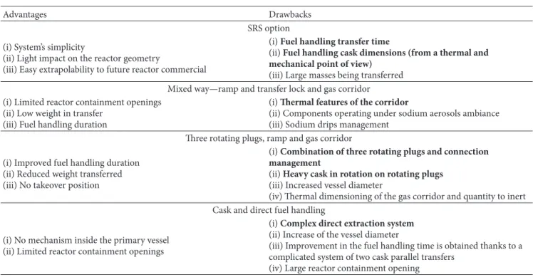
A graphical representation in Figure 19 presents each solution regarding the others.
In Figure 19 four parameters are set: performances (x-axis), risks assessment (y-axis), qualiication time (colour from red to green), and investment cost compared to the SRS option (higher = triangle or equivalent = circle). his view simply reveals that the “cask and direct fuel handling” system provides no improvement regarding the SRS option (and safety aspects are very low). he two solutions with gas corridor provide signiicant improvement in terms of performances with a good conidence in the qualiication time. he radar diagram plotted for each solution and based on ive major criteria is deinitely helping for inal decision (Figure20).
0 2 4 6 8 10 Availability Safety impact Geometrical performance Thermal and mechanical performance Design simplicity and robustness SRS 0 2 4 6 8 10 Availability Safety impact Geometrical performance Thermal and mechanical performance Design simplicity and robustness Mixed way 0 2 4 6 8 10 Availability Safety impact Geometrical performance Thermal and mechanical performance Design simplicity and robustness
Cask and direct fuel handling
0 2 4 6 8 10 Availability Safety impact Geometrical performance Thermal and mechanical performance Design simplicity and robustness
3 rotating plugs, ramp and gas corridor
Figure 20: Performance of the options (“radar” diagram).
Table 1: Advantages and drawbacks of the reference solution plus the innovative solution investigated.
Advantages Drawbacks
SRS option (i) System’s simplicity
(ii) Light impact on the reactor geometry
(iii) Easy extrapolability to future reactor commercial
(i) Fuel handling transfer time
(ii) Fuel handling cask dimensions (from a thermal and
mechanical point of view)
(iii) Large masses being transferred Mixed way—ramp and transfer lock and gas corridor (i) Limited reactor containment openings
(ii) Low weight in transfer (iii) Fuel handling duration
(i) hermal features of the corridor
(ii) Components operating under sodium aerosols ambiance (iii) Sodium drips management
hree rotating plugs, ramp and gas corridor (i) Improved fuel handling duration
(ii) Reduced weight transferred (iii) No takeover position
(i) Combination of three rotating plugs and connection
management
(ii) Heavy cask in rotation on rotating plugs (iii) Increased vessel diameter
(iv) hermal dimensioning of the gas corridor and quantity to inert Cask and direct fuel handling
(i) No mechanism inside the primary vessel (ii) Limited reactor containment openings
(i) Complex direct extraction system (ii) Increase of the vessel diameter
(iii) Improvement in the fuel handling time is obtained thanks to a complicated system of two cask parallel transfers
Table 2: Cost and risks aspects of the three FHR compared to the SRS option.
Criterion proposed SRS Mixed way
3 rotating plugs, ramp and gas
corridor
Cask and direct fuel handling
Manufacturing cost analysis = = > >
Development and qualiication Medium Medium Medium Very long
Technical rest (of not achieving performance) Medium Medium Medium high
Safety risks Medium low low high
2 1,5 1,5 3
hus, based on the analysis above, the following orienta-tions are recommended.
(i) Studies on the mixed way—ramp and transfer lock and gas corridor—are pursued due to advantages of this solution, in order to go in detail in its potentiality, especially in the improvement of the load factor and its simplicity in designing the cask.
(ii) he option on the three rotating plugs, ramp and gas corridor is not retained due to technological breakthrough.
(iii) he option on cask and direct fuel handling provides technological diiculties and is not retained.
8. Conclusions
his study has revealed that the corridor option has to be reconsidered even if the SRS remains the reference option for ASTRID reactor. Advantages of this mixed way option such as load factor improvement and design simplicity have to be conirmed. he study of a complete fuel handling route (from the primary vessel until the EVST) is interesting in the way that it helps providing new ideas (e.g. the gas corridor or the cross-building airlock). Some speciic innovative aspects can therefore be pointed out even if the whole FHR appears to be too challenging for a SFR reactor. Nonetheless the SRS version also involves technological issues, especially the sodium pot cask which has to transfer an assembly at a high residual power (around 40 kW). As the continuation of this study, efort will be put on the mixed way—ramp and transfer lock and gas corridor. In parallel the thermal and mechanical aspects of the sodium pot cask have to be performed.
Nomenclature
ACS: Above Core Structure
ASTRID: Advanced Sodium Technological Reactor for Industrial Demonstration BOP: Balance of plant
CCS: Core Cover Structure DHR: Decay heat removal ECS: Energy conversion system EVST: External vessel storage tank FHS: Fuel handling system FHR: Fuel handling route
lp170ptIHX: Intermediate heat exchanger HTMP: Horizontal transfer mechanism pot ISIR: In-service inspection and repair LRP: Large rotating plug
R&D: Research and development RP: Rotating plug
SCO: Speciic component optimization SFR: Sodium-cooled fast reactor SRP: Small rotating plug SRS: Starting reference solution.
Conflict of Interests
he authors declare that there is no conlict of interests regarding the publication of this paper.
Acknowledgments
he authors would like to thank Bertin/CNIM and COMEX Nucl´eaire engineering companies for their works and contri-bution in bringing alternative and innovative solutions to sys-tems which were so far from their current works. In particular the authors provide special thanks to MM. G. Rainaud and D. Dumont for their works on the cask and direct fuel route and MM. D. Roulet and M. Macia and their engineering team for their work on the three rotating plugs, ramp and gas corridor route. M. Saez (CEA) kindly accepted to read this text at all the steps and made important comments, observations, and suggestions now fully integrated in the present version.
References
[1] F. Gauch´e and J. Rouault, “French SFR R&D program and design activities for SFR prototype ASTRID,” Energy Procedia, vol. 7, pp. 314–316, 2011.
[2] P. Le Coz, J. F. Sauvage, and J. P. Serpanti´e, “Sodium-cooled fast reactors: the ASTRID plant project,” in Proceedings of the Inter-national Conference of Asian Political Parties (ICAPP ’11), Nice, France, May 2011.
[3] M. Saez, S. Menou, and B. Uzu, “he pre-conceptual design of the nuclear island of ASTRID,” in Proceedings of the Interna-tional Conference of Asian Political Parties (ICAPP ’12), p. 12070, Chicago, Ill, USA, June 2012.
[4] G. Rodriguez, M. Saez, M. Levy et al., “Review and innovative technologies on fuel handling system for sodium fast reactors,”
in Proceedings of the7th International Conference on Advanced Nuclear Fuel Cycles and Systems (GLOBAL ’07), Boise, Idaho, September 2007.
[5] Y. Chikazawa, M. Farmer, and C. Grandy, “Technology gap analysis on sodium-cooled reactor fuel-handling system sup-porting advanced burner reactor development,” Nuclear Tech-nology, vol. 165, no. 3, pp. 270–292, 2009.
[6] G. Pr`ele, G. Rodriguez, E. Sanseigne, M. Chassignet, and C. Majot, “Some experimental feedback of the fuel handling sys-tem of French sodium fast reactors regarding speciic opera-tions: cleaning, refuelling, inal defueling,” in IAEA Technical Meeting on Fuel Handling Systems of Sodium Cooled Fast Reactors, pp. 24–27, IGCAR, Kalpakkam, Tamil Nadu, India, November 2008.
[7] G. Pr`ele, C. Latg´e, R. Dupraz, and J. P. Dirat, “Feedback experience from sodium technology,” Revue G´en´erale Nucl´eaire RGN no. 1, Janvier-F´evrier 2009.
[8] G. Srinivasan, K. V. Suresh Kumar, B. Rajendran, and P. V. Ramalingam, “he fast breeder test reactor-design and operat-ing experiences,” Nuclear Engineeroperat-ing and Design, vol. 236, no. 7-8, pp. 796–811, 2006.
[9] K. V. S. Kumar, A. Babu, B. Anandapadmanaban, and G. Srinivasan, “Twenty ive years of operating experience with the fast breeder test reactor,” Energy Procedia, vol. 7, pp. 323– 332, 2011.
[10] P. Chellapandi, P. Puthiyavinayagam, V. Balasubramaniyan et al., “Design concepts for reactor assembly components of 500 MWe future SFRs,” Nuclear Engineering and Design, vol. 240, no. 10, pp. 2948–2956, 2010.
[11] A. Katoh, Y. Chikazawa, H. Obata, and S. Kotake, “Development of advanced fuel handling machine for JSFR,” Journal of Nuclear Science and Technology, vol. 47, no. 7, pp. 642–651, 2010. [12] D. Cacuci, “Handbook of nuclear engineering,” in Sodium Fast
Reactor Design: Fuels, Neutronics, hermal-Hydraulics, Struc-tural Mechanics and Safety, chapter 21, pp. 2321–2711, Springer, New York, NY, USA, 2010.
[13] M. Chassignet, S. Dumas, C. Penigot et al., “Challenges and innovative technologies on fuel handling systems for future sodium-cooled fast reactors,” Journal of Nuclear Science and Technology, vol. 48, no. 4, pp. 662–668, 2011.
[14] J. C. Lef`evre, C. H. Mitchell, and G. Hubert, “European fast reactor design,” Nuclear Engineering and Design, vol. 162, pp. 133–143, 1994.
[15] F. Dechelette, S. Christin, E. Sanseigne et al., “Study and evalu-ation of innovative fuel handling systems for SFRs—part 2 : single component optimization,” IAEA-CN-199-123, FR13, Paris, France, March 2013.
[16] F. Morin and F. Dechelette, “Transfert innovant d’assemblages combustibles pour un RNRNA de la cuve r´eacteur vers un stockage externe d´eport´e,” French Patent HD 13521, June 2012. [17] IAEA, “Fast Reactor Database,” IAEA TECDOC no. 1531, 2006. [18] K. J. Henry, “Technical description of PFR,” Nuclear Engineering
International, vol. 16, no. 183, pp. 632–636, 1971.
[19] C. R. Hunt, P. L. Riley, and N. Campbell, “Fuel handling and other In-reactor mechanisms in PFR,” in Proceedings of the International Conference Fast Reactor Power Stations, pp. 11–14, London, UK, March 1974.
[20] D. B. Melhuish, “Engineering improvements to PFR,” Nuclear Energy, vol. 31, no. 3, p. 193, 1992.
Submit your manuscripts at
http://www.hindawi.com
Hindawi Publishing Corporation
http://www.hindawi.com Volume 2014
Structures
Journal ofMachinery
Hindawi Publishing Corporation
http://www.hindawi.com Volume 2014
Industrial EngineeringJournal of
Hindawi Publishing Corporation
http://www.hindawi.com Volume 2014
Advances in
Tribology
Hindawi Publishing Corporation
http://www.hindawi.com Volume 2014
Hindawi Publishing Corporation
http://www.hindawi.com Volume 2014
Hindawi Publishing Corporation http://www.hindawi.com
Journal of
Engineering
Volume 2014
Hindawi Publishing Corporation
http://www.hindawi.com Volume 2014 International Journal of
Photoenergy
Hindawi Publishing Corporation
http://www.hindawi.com Volume 2014
Science and Technology of
Nuclear
Installations
Hindawi Publishing Corporation
http://www.hindawi.com Volume 2014
Solar Energy
Journal ofHindawi Publishing Corporation
http://www.hindawi.com Volume 2014
Power Electronics
Hindawi Publishing Corporation
http://www.hindawi.com Volume 2014
Advances in
Fuels
Journal ofHindawi Publishing Corporationhttp://www.hindawi.com Volume 2014
Hindawi Publishing Corporation
http://www.hindawi.com Volume 2014
Nuclear Energy
International Journal ofHindawi Publishing Corporation
http://www.hindawi.com Volume 2014 High Energy PhysicsAdvances in
Hindawi Publishing Corporation
http://www.hindawi.com Volume 2014 Mechanical Engineering Advances in Journal of Petroleum Engineering
Hindawi Publishing Corporation
http://www.hindawi.com Volume 2014
The Scientiic
World Journal
Hindawi Publishing Corporation
http://www.hindawi.com Volume 2014
Journal of
Hindawi Publishing Corporation
http://www.hindawi.com Volume 2014
Renewable Energy
Combustion
Journal ofHindawi Publishing Corporation