The Development and Characterization of Soft Robotic Contractile Actuators
MASSA 0 by Sarah T. HuaL
Submitted to theDepartment of Mechanical Engineering
in Partial Fulfillment of the Requirements for the Degree of
Bachelor of Science in Mechanical Engineering at the
Massachusetts Institute of Technology
June 2019 CHUSETTS INSTITUTE F TECHNOLOGY
JL
162019
IBRARIES
RCHIVES
2019 Sarah T. Hua. All rights reserved.
The author hereby grants to MIT permission to reproduce and to distribute publicly paper and electronic copies of this thesis document in whole or in part in any medium now known or hereafter created.
Signature of Author:
Signature redacted
Department of Mechanical Engineering
Signature redacted
May 9, 20191,2-C)
t
9
Ellen Roche Assistant Professor, Mechanical Engineering and Institute for Medical Engineering and Science
Signature redacted
Thesis SupervisorAccepted by:
Maria Yang Professor of Mechanical Engineering Undergraduate Officer Certified by:
The Development and Characterization of Soft Robotic Contractile Actuators
bySarah T. Hua
Submitted to the Department of Mechanical Engineering on May 9, 2019 in Partial Fulfillment of the
Requirements for the Degree of Bachelor of Science in Mechanical Engineering
ABSTRACT
In this paper, I describe the development of a soft-robotic myocardium and pneumatic artificial muscles (PAMs) that replicate the physiological motion of the heart. We were able to generate physiological twisting motion in a confined geometry, but additional actuators would be required to generate physiological force for blood ejection. However, McKibben PAMs with thermoplastic polyurethane (TPU) bladders were too bulky and prevented the embedding of additional actuators. Therefore, multiple alternate PAM designs which occupy minimal unpressurized volume were explored. Of the various bladder and mesh pairings for traditional McKibben PAMs, latex bladders with nylon braided mesh proved the most promising. 2D PAMs with zero volume bladders were also developed: 2D McKibben, 2D Pleated, and 2D Cardiac Geometry PAMs. Candidate PAMs were characterized and compared to the physiological linear contraction (14.7%) and force generation (60N) of the heart. The 2D PAMs successfully reduced the volumetric footprint and were able to generate a maximum force of 0.46 N/cm3 (7mm-width five channel 2D McKibben PAM matrix), close to the amount generated by the baseline TPU PAMs (0.53 N/cm3), and up to 10.1% linear contraction (3mm-width nine channel 2D McKibben PAM matrix). However, none of the PAM matrices characterized were able to meet both linear contractile and force generation targets. With more characterization and iteration, the 2D PAMs seem promising for the biomimetic soft-robotic myocardium application.
Thesis Supervisor: Ellen Roche
Acknowledgements
I would like to thank Clara Park for taking me onto the soft-robotic myocardium
project and providing me insight and guidance along each and every step of the way. I
would like to thank Professor Ellen Roche for accepting me into her lab and for her
extensive knowledge and guidance regarding soft-robotics in the cardiac space. I would
like to thank Markus Horvath for training me on the Instron and helping to set up the
characterization tests. I would like to thank Professor John Brisson for his advice and
for introducing me to Professor Ellen Roche. Finally, I would like to thank my family
Table of Contents
Table of Contents... 7 List of Figures ... 8 1 . Introduction ... 9 2. Background... 11 2.1 Cardiovascular Physiology... 112.2 Pneum atic Artificial M uscles (PAM s) ... 14
2.3 Previous Cardiac Applications Using PAM s ... 16
3. Geom etry, M otion, and Force Considerations ... 19
4. Program m ing Physiological Twisting M otion... 21
5. Initial Screen... 27
6. Developm ent of 2D PAM s ... 30
7. Characterization of Candidate system s... 33
7.1 Candidate System s ... 33
7.2 Linear Contractile Characterization ... 34
7.3 Observed Failure M odes ... 35
7.4 Force Generation Characterization... 36
7.5 Experim ental Lim itations ... 37
8. Experim ental Results... 38
8.1 10m m TPU M cKibben PAM ... 38
8.2 1/16" Latex M cKibben PAM ... 40
8.3 7m m 2D M cKibben PAM ... 41
8.4 3m m 2D M cKibben PAM ... 43
8.5 7m m 2D Pleated PAM ... 43
8.6 2D Cardiac Geom etry M cKibben PAM ... 45
8.7 Overall Force Com parisons... 46
9. Conclusions ... 47
10. Future Steps ... 49
List of Figures
Figure 1. Cardiac Anatom y... 11
Figure 2. Volum etric Change During Contraction ... 12
Figure 3. The Cardiac Cycle ... 13
Figure 4. M yofiber Orientation... 14
Figure 5. Coupling Visualization... 15
Figure 6. Types of PAM s... 16
Figure 7. Actuator Orientation... 17
Figure 8. Preparation of the Fixed Porcine Heart ... 21
Figure 9. Positioning of the PAM s ... 23
Figure 10. Helical Twisting M otion... 24
Figure 11. PAM Positioning Shells ... 26
Figure 12. Adhesion Characterization ... 27
Figure 13. Expansion Characterization... 29
Figure 14. 2D PAM Components ... 30
Figure 15. Cardiac Tissue Geom etry ... 31
Figure 16. Com ponents of PAM s to be Characterized ... 33
Figure 17. Im age Analysis ... 35
Figure 18. Force Generation over Tim e... 36
Figure 19. 10m m TPU M cKibben PAM ... 40
Figure 20. 1/16" Latex M cKibben PAM ... 41
Figure 21. 7m m 2D M cKibben PAM ... 43
Figure 23. 3m m 2D M cKibben PAM ... 44
Figure 24. 7m m 2D Pleated PAM ... 45
Figure 25. 2D Cardiac Geom etry M cKibben PAM ... 46
Figure 26. Maximum Scaled Force Generated over Maximum Contraction for all Matrices... 47
Figure 27. Force Scaled to Total Volum e:... 47
1. Introduction
Soft robotics can be defined as robotics built with soft, compliant materials rather than rigid
ones. While traditional robotics are widely used and can be specifically programmed to perform
specific tasks efficiently, they often lack flexibility and can be unsafe for direct interaction with
humans and other organisms. Soft robotics, on the other hand, are capable of producing many
motions that are challenging in traditional robotics such as bending, twisting, and adapting to
the surrounding environment. Consequently, soft robotics have been used to mimic many
biological behaviors that traditional robotics often cannot replicate including complex
physiological motions. Some previous examples of this include the replication of linear muscle
fibers, biomimetic locomotion , and replicating sensing in flexible systems [1].
In this work, we are seeking to replicate the motion of the heart. As the heart beats, it
creates a compressive motion as well as a helical twisting motion during systole allowing the
heart to circulate blood through the body. Replication of accurate physiological heart motion
is important for both clinical treatment of heart failure patients [2] and development of a
realistic cardiovascular simulator for testing of intracardiac devices. Currently, intracardiac
medical devices are tested on a variety of systems. Some systems are completely synthetic and
replicate the perfusion and pressures generated by the heart [3] Other systems use an ex vivo
heart to capture the internal geometry and are driven by internal pressurization of the heart [4].
However, this creates a contradictory pressure flow as the chambers are filled with high
pressure fluid and increase volume during systole while physiologically, systole is a state of
high pressure and low volume [5]. While the synthetic and ex vivo systems are able to replicate
the pressure generation and hemodynamics, they do not capture the physiological motion of
the heart. Two types of systems, the ex vivo Langendorff process [6] and in vivo animal-studies
recreate this motion for testing, however both involve time-intensive preparations and only last
heart it would provide a more accurate environment for testing of intra-cardiac devices without
the high cost and difficulty of in vivo testing.
With our model, we aim to accurately replicate the pressure and force generation of the
heart but also the physiological motion. In this study, we seek to develop a soft robotic
myocardium embedded with soft pneumatic artificial muscles in a confined geometry that will
actuate a fixed porcine heart with its myocardial tissue removed. In order to gauge the accuracy
of our model, we will compare the soft robotic myocardium to physiological metrics for force
generation, helical rotation, and linear contraction.
2. Background
2.1 Cardiovascular Physiology
The heart is the muscular organ that pumps blood through the circulatory system by
means of rhythmic filling and ejection. The heart is comprised of four primary chambers:
the left atrium, the left ventricle, the right atrium, and the right ventricle. The right side of
the heart serves to pump blood to the lungs to become oxygenated while the left side of the
heart then pumps oxygen rich blood to the body. The ventricular chambers of the heart are
surrounded by the myocardium, the muscular tissue of the heart.
Aorta Superior Vena Cava Pulmonary Artery Left Atrium
Right Atrium Left
Ventricl
Interventricular Septum
Figure 1. Cardiac Anatomy: Areas of focus for our purposes are the left and
right ventricles and the myocardial tissue surrounding them. [7]
Physiologically, the average human heart pumps blood approximately 5 liters of blood to
the body per minute. This pumping volume is generated from the systolic and diastolic phases
of the heart. During the diastolic phase, the myocardium relaxes and the ventricles fill with
blood. During the systolic phase, the heart contracts circumferentially and helically and the myocardial tissue thickens, reducing the ventricular volume by, and generating and ejection fraction of, approximately 63% [8].
SYSTOLE DIASTOLE
Heart muscles Heart muscles
Contract Relax
Figure 2. Volumetric Change During Contraction: During the systolic phase,
the cardiac wall tissue thickens as the myofibers contract, reducing the volume of the ventricles, and generating volume displacement. [9]
In order to replicate the cardiac cycle, the hemodynamics (the dynamics of blood flow) must be replicated. The system must be able to control and direct blood flow in a similar manner to the cardiac cycle, which is easily visualized by observing the generated pressure gradients (Figure 3). During diastole, the left ventricular pressure is low, ranging from 0-10mm Hg, however, during systole, the left ventricular pressure rapidly increases as the myocardium contracts to a peak of 115-120mm Hg before returning to low pressure once again.
Semnilunar 120- valves close Somilunar 100 - valves open Aortic pressure
G0-40- Ventricular pressut AV valves AV valves open 0 Atrial pressure 1 1St 2nd 3rd
Head sounds A&.
LuW "Dub
Figure 3. The Cardiac Cycle: Plotting of aortic, left ventricular pressure and left
atrial pressure during the pumping of the heart. [10]
Currently, many cardiac simulators can accurately replicate these pressure changes and hemodynamic behaviors. However, these hemodynamic patterns are a result of the heart's unique physiological pumping motion which current simulators have not been able to replicate. As we are interested in replication of not only the hemodynamics of the heart but also the physiological pumping motion, our primary area of interest are the ventricles. We will primarily focus on the myocardium surrounding the left ventricle as the pressure generation and compression into the body requires significantly more pressure and force than the right ventricle.
In order to understand the physiological pumping motion of the heart, we must first understand the architecture of ventricular myocardium. The myocardium is the muscular tissue surrounding the heart which is composed of many myofibers. In previous studies, the orientation of myofibers has been characterized helical myofibers oriented 30 degrees from the vertical which are positioned around the ventricle and circumferential myofibers.
Basal rotation (clockwise)
Figure 4. Myofiber Orientation: Helical and circumferential myofiber
orientations can be observed in cardiac tissue [11]
Due to this orientation, as the myofibers contract linearly, the physiological twisting motion and compressive motion is generated. The circumferential myofibers provide more of the volume displacement than the helical myofibers; in a soft robotic sleeve it was found that the circumferential myofibers produced 38 ml displacement while the helical myofibers produced only 22ml [2] as they contract. The contraction of both sets of myofibers causes the overall myocardium to thicken and twist during systole and generate the pumping motion of the heart.
2.2 Pneumatic Artificial Muscles (PAMs)
Pneumatic Artificial Muscles (PAMs) are linear and contractile motion actuators that are operated by fluid pressurization. PAMs are composed of two primary components, an inflatable membrane bladder and an external element such as textiles or mesh that limits radial expansion past a specific amount and converts the motion to linear contraction. The bladder is coupled to the non-extensible element so that as the bladder radially expands, the non-extensible element causes the PAM to linearly contract.
_<4
srr ht'd
at re",t
pressurized
Figure 5. Coupling Visualization: A McKibben type PAM demonstrating the
coupling between radial expansion and linear contraction which generates force at varying stages of pressurization [12].
Due to the composition of PAMs, they are typically lightweight but are still able to generate high levels of force making them well suited to a variety of fields such as robotics, industrial automation, and the replication of physiological motions [1]. The materials and geometry of both components influences the motion and force output of the actuator and can be varied depending on the needs of the actuator such required force generation, maximum pressure, and size limitations.
Currently, there are many PAM designs that are used, some of which include the McKibben Muscle and the pleated PAM. The most widely used is the McKibben Muscle which couples a membrane bladder to a braided mesh by attaching the ends of the bladder to the ends of the mesh. Pleated PAMs are similar with a membrane bladder but instead of a braided mesh, pleated PAMs have longitudinal fiber pleats constraining the bladder.
(a) (b) (C) (d)
Figure 6. Types of PAMs: (a) depressurized McKibben, (b) pressurized McKibben, (c) depressurized pleated, and (d) pressurized pleated [12][13].
Due to the high level of versatility, PAMs are not widely commercially produced, instead they are more commonly custom formed in house for specific use cases which can lead to fabrication variability between samples.
2.3 Previous Cardiac Applications Using PAMs
In order to develop a PAM for our use case, other similar applications were researched. PAMs have been used for a variety of functions in soft robotics and has begun to be used in the cardiac space. One project sought to develop a biomimetic cardiac simulator using soft robotics [14] , and subsequently developed a soft robotic extra-cardiac compression device to provide a cardiac assistance for the treatment of heart failure [2]. In this study, various silicone, TPU, and nylon PAMs were compared first to determine which would be best suited for generating the force and twist needed to assist cardiac compression. TPU bladders were found to perform well and were easily fabricated so were selected [15]. The cardiac sleeve aimed to accurately
A
replicate the helical twisting motion of the heart and volume displacement of blood during
compression by positioning PAMs in both circumferential and helical orientations [2].
Compress Twist Compress,
decompress Untwist decompress
Twist, untwist
Figure 7. Actuator Orientation: An example of how layering of helical and circumferential actuators were layered to generate the physiologically accurate compressive motion [21
Once embedded in the fabric sleeve, the system was tested to see if it could generate the
targeted ION total force generation which had been determined the suitable amount for a direct
cardiac compression device (ref - you could explain this calculation too).
The research compared four types of internal bladders in a McKibben type PAM to
determine which bladders were able to achieve the target force generation and motion. The
bladder types characterized included low durometer silicone tubing, polyester terephthalate
(PET) tubing, nylon medical balloons, and thermoplastic urethane (TPU) balloons that were
thermally formed in house. '
In the study, TPU PAMs were characterized to collectively produce
1ON
of force andcontraction of 30% under 8OkPa for a 200ms period which was deemed appropriate for the
functionality of the heart sleeve and superior to the other options. Another design consideration
was that TPU bladders could be fabricated in house and customized while nylon medical
modified without custom tooling. Once embedded, the sleeve was able to assist the heart in
replication of the compressive and helical physiological motion. Therefore, we decided to use
TPU bladders for our first attempt at generating a silicone soft robotic myocardium. The study
also compared the positioning of the circumferential and helical actuators and found that due
to the fact that the helical motion does not generate much compressive force, the optimal
orientation is the helical actuators positioned with the circumferential actuators outside as this
was able to generate 31.25 % more force than the inverse orientation [2] [14]. Based on these
results, we decided to utilize the TPU PAMs, helical positioning, and overall layering of PAMs
in our first iteration of the soft-robotic myocardium.
3.
Geometry, Motion, and Force Considerations
To determine the linear contraction required, we started by calculating the volume
contraction required using averaged values from adult human hearts. The average left
ventricular volume of an adult human heart is 142mL during diastole [16] with an average
volumetric ejection rate of 75mL/beat. This results in approximately 52.8% volumetric ejection.
Scaling this to the porcine hearts which we are using, we are seeking a 52.8% volumetric
contraction rate from the initial 108nL volume calculated from the fixed porcine heart to 51 mL.
Because we are using the same PAMs for both the circumferential and helical contraction, we
will approximate that the linear contraction from both will be relatively equivalent and evenly
scale the compressed dimensions to an upper radius of 1.91cm and height of 4.25cm
(uncompressed values of r = 2.3cm and h = 6.5cm). This results in approximately 35% linear
contraction required. However, this does not account for the volumetric change created by the
PAM bladders' radial expansion from 3mm diameter to approximately four times the size.
Accounting for this, the amount of linear contraction required from the actuators drops to 14.7%
as some of the contraction comes simply from the inflation of the bladders themselves. In order
to ensure that we are able to generate sufficient linear contraction, we target a linear contraction
of 20%.
In order to determine the force generation required, we will use the average adult human
systolic pressure of 16 -N (I20mmHg). In order to calculate force generation required we will
use the tensile pressure equation T - PassistAx [15]. The calculated surface area of our
2
myocardium at the inner ventricular boundary is 127.17 cmA2 resulting in a total force required
from the system to be 60N. Depending on the size of the actuators, different numbers of PAMs
whole rather than individual actuators. Finally, the actuators must robust enough to be
pressurized repeatedly without failing.
_ - - -I
4. Programming Physiological Twisting Motion
For the initial design, the twisting motion was first targeted as we felt that this would be a
more difficult motion to replicate. Previously, this motion had been achieved in a cardiac
simulator through the placement of helical actuators external to the heart [15][17]. In order to
achieve this, we decided to develop an integrated soft robotic myocardium in combination with
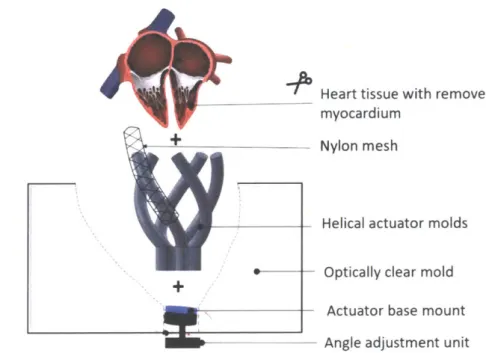
endocardial tissues from a porcine heart. The fabrication process used for this involves
multi-step molding multi-steps. First, the external geometry of a porcine heart is first used to create an outer
mold. Next, the myocardium tissue of the porcine heart is removed while leaving the
endocardial layer intact. Then, we pour silicone into this place, replacing organic tissue with
synthetic myocardium. In the same step, we also embed soft robotic actuators to make the
synthetic myocardium soft robotic. For our design, the inner geometry of the ventricular tissue
was measured and used to create positioning arms for the PAMs.
Mold outer ventricular wall [ Remove myocardial tissue
O!uter mold.
Figure 8. Preparation of the Fixed Porcine Heart: Initial steps taken in order
to obtain the outer geometry of the myocardium and the removal of the myocardial tissue while leaving the endocardial layer intact
The left ventricular endocardial tissue was measured have an upper medial circumference
of 5.09cm, a lower medial circumference of 2cm, and height of 6cm. We selected Ecoflex
00-20 Silicone (Smooth-00-20) silicone to mold the myocardium as it had the closest Young's
Based on the results from the cardiac simulator study, we decided to use PAMs as our soft
robotic actuators [15]. After testing, the study concluded a combination of a 1/4" Nylon mesh
with a four times expansion ratio and thermoplastic polyurethane (TPU) bladders to provide
the best force generation [15]. The positioning and orientation of the PAMs was decided based
on the helical outer myofiber orientation in the heart, 30 degrees from the vertical, oriented
clockwise from the base. The spacing between helical actuators from previous studies, which
found that for embedded actuators in Ecoflex (in the case of this study, Ecoflex 00-30), the
spacing that generated the highest strain was a singular actuator diameter spacing between each
actuator while the highest force was generated with four times actuator diameter spacing [14].
The TPU actuators from the cardiac sleeve had an approximate resting diameter of 9mm, we
placed 5 TPU actuators evenly apart for the first iteration. Once the positioning was determined,
helical positioning arms and a base with keyhole slots to hold the positioning arms in place
were modeled in SolidWorks and 3D printed using an Object30 Prime 3D printer and
VeroBlack and VeroWhite filament according to specification. The positioners were designed
to be removed after casting, to leave cavities in the orientation required in the silicone
myocardium while leaving a port in which the actuators could be inserted. Alignment relative
to tissue geometry can be adjusted using the magnetic angle tilter in order to assure that
actuators are fully embedded.
' Heart tissue with removed myocardium
Nylon mesh
Helical actuator molds
Optically clear mold
Actuator base mount Angle adjustment unit
Figure 9. Positioning of the PAMs: Using the 3D printed spacers, meshes can
be fixed in specific configurations in the silicone. Once positioned and fixed, the spacers would be removed and TPU bladders would be inserted in the generated cavities.
Initially, we fabricated coupled PAMs where the mesh was fixed at the end of the bladder
according to the method previously described in the cardiac simulator paper [15], and planned
to insert the entire coupled system into the cavities in the silicone. In order to test integration
with the silicone, we first fabricated flat silicone matrices with cavities. Next, the coupled
PAMs were inserted and inflated in order to test the behavior. However, upon testing we found
that force was not consistently being transferred into the silicone matrix; instead, force was
largely lost and the PAM simply contracted within the cavity and the only force generated came
from the radial expansion of the PAM. To address this, we decided to instead directly integrate
the mesh into the silicone by placing the mesh on the spacers before molding the silicone on
top. This would then leave a cavity within the mesh for the actuator bladders to be inserted into.
(c)
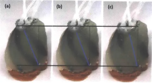
Figure 10. Helical Twisting Motion The first iteration actuated at (a) 0, (b) 5, and (c) 10
psi. Linear contraction and helical rotation are visible
However, in order to refine the model, another design change was made to design and fabricate smaller, 5mm diameter actuators as the 9mm actuators were unable to fully embed into the silicone myocardium and were only able to fit five actuators. The mesh remained unchanged. In order to maintain the optimal strain generation spacing while accounting for space limitations at the base, the design was adjusted to have 8 evenly spaced actuators while keeping the angle overall height and size the same as the first iteration and reprinted (Fig. 10).
Figure 10. Adjusted Positioning Arms: In order to accommodate a smaller diameter actuator, the spacers were redesigned and 3D printed.
After manufacturing the second iteration, the soft robotic myocardium was placed over a tissue analog of the endocardial tissue and actuated at 5psi and 1 Opsi. From these tests, a helical twisting motion was observed which led to believe that this model could be an accurate replication with more tuning. Shortcomings of the initial design are that it fails to incorporate the circumferential compression of the heart and that delamination of the mesh from silicone matrix was also observed. Due to their size, the actuators and meshes were still unable to fully embed into the silicone and often had areas where they protruded.
In order to address the limitations of the first iteration, it became evident that new PAMs would be needed. In order to generate sufficient force and contraction, both helical and circumferential actuators are needed [15]. The previous PAMs were too large to layer both circumferential and helical actuators within the boundaries of the myocardium and were also running into other issues such as delamination from the silicone. Due to the measured thickness of the myocardium being a maximum of 10mm, we set a target diameter for our new PAMs to be 2-3mm so that the helical and circumferential PAMs can both be fully embedded.
With the actuators being this small, we concluded it would be challenging to use the
previous insertion method so we developed a new fabrication method to account for the
placement of both the circumferential and helical actuators. This new method was comprised
of a two-step molding process (Fig. 12). First, PAMs are positioned on the intermediary shell
with helical placed inside of the circumferential, this order was determined by higher force
generation [2]. Next, an outer shell is placed over the actuators and intermediary shell. The
outer shell has an outlet at the top where the tubings for the PAMs can exit and serves as the
pouring point for the Ecoflex-0020 (Smooth On) as well. Once the Ecoflex-0020 has cured, the
PAMs will be half-embedded within the silicone, this allows for the removal of the
intermediary shell as the half-embedded PAMs are held in their position. Next, an inner shell
is placed and Ecoflex-0020 is once again poured into the cavity. This time, it will fill between
the exposed PAMs and the inner shell, fully embedding the actuators. All of the shells are held
in place by positioning features on the base. This design will allow us to capture both the helical
and circumferential compressive physiological motion of the heart.
Figure 11. PAM Positioning Shells: From left to right, the intermediary shell with placement grooves, the intermediary and outer shell with cavity to be poured, and the outer and inner shells with the overall cavity size.
5.
Initial Screen
In order to efficiently test various PAM possibilities, we first decided to do a qualitative
initial screening of different possibilities. As PAMs are comprised of two components, a
bladder and a mesh, we decided to first test options individually. For bladders, we decided to
explore both compliant and non-compliant versions and explored various materials. Compliant
materials tested included Latex tubing (McMaster), Silicone Rubber Tubing, Chronoprene
tubing, and Styrene Ethylene Butylene Styrene (SEBS) bladder made out from heat-sealing
two sheets. Non-compliant materials tested were PET Medical Balloons, Pebax Tubing, and
TPU bladders which serve as our baseline. The first test we decided to conduct was an adhesion
test in order to determine whether or not robust, sealed bladders could be produced. The
adhesion test consisted of adhering two small pieces of each material with various adhesives,
allowing the adhesives to set, and then testing to see how much force was required to
delaminate the bond and how the bond broke. We tested various adhesives as well as heat
sealing and physical sealing for the various materials.
Silpoxy Loctite Epoxy Heat Shrink Impulse Heat Tubing Sealing Latex Tubing
(1/16" ID, 1/8") Delaminates within Withstands Doesn't adhere n/a No the seal and along significant force at interface
the interface before yield
PET Medical Balloon
(6mm x 200mm) Peeling occurs with Peeling occurs with Doesn't adhere Did not adhere Deformed and relatively low force medium amount of at interface well to either flattened but did
force balloon or tubing not seal
Pebax 35D Tubing Deformed and
( 0.156" OD 0.146" ID) Adhered very well Did not adhere at Did not adhere at n/a flattened. Didn't interface interface fuse, easily
broken by pressure
Figure 12. Adhesion Characterization: Characterization of adhesion between
From these, we determined that delamination was a large issue at the seams between the
material as well as between the bladder and the tubing and that creating an airtight bladder
proved extremely difficult. We therefore eliminated PET Medical Balloons and Pebax Tubing
as options as we were unable to successfully create airtight bladders that could withstand the
pressure needed.
Next, the remaining materials were evaluated on diameter size, durometer, wall-thickness,
expansion ratio, elongation ratio, and burst pressure. Size, durometer wall-thickness, and burst
pressure measurements were taken from the material specification sheets when available and
measured manually if not. Expansion ratio and elongation ratio were measured manually by
comparing the size and length of the bladder at rest and after full inflation. Various meshes
were also tested and characterized in order to determine their expansion ratios and integration
into silicone as delamination was previously an issue. In order to maximize linear contraction
and force generation, the expansion ratios of the bladders were compared with those the varying
meshes in order to determine optimize coupling.
(a)
ID OD Durometer Wall Max Max Max Burst Thickness Expanded Expansion Elongation pressure
Diameter ratio ratio
Latex tubing 1/16" 1/8, 40A 0.03125" 0.54" -4X -2-3X 25 psi
Smaller 0.058" 0.077" 50A 0.0095" 0.077" IX iX 5 psi
Rubber
Chronoprene 0.055" .060" 25A 0.005" 0.3937" -7.15X >2X <5psi
tubing - - __ _ _I__
Chronoprene 0.107" 0.112" 40A 0.005" 0.75" -7X >2X <5psi
tubing
(b)
D-min D-max Expansion Stiffness Springs Embeds in
ratio back? silicone?
1/4" Cotton 0.15" 0.3" 2X Low No Yes
1/8" Cotton 0.10" 0.3" 3X Low No Yes
1/8" High Density 0.14" 0.5" 3-4X Medium Yes Delaminates
Fine Thread
1/4" High Density 0.15" 0.3" 2X Medium Yes Delaminates
Fine Thread
1/16" FlexoThin 0.067" 0.17" 4X Low Yes Yes
1/4" FlexoThin <1/4" 1" > 4X Low No Yes
1/4" Thin Nylon 0.15" 0.5" 3-4X High Yes Delaminates Mesh
Figure 13. Expansion Characterization: Characterization of expansion ratios
and integration with silicone for (a) bladders and (b) meshes as well as testing other factors such as maximum pressure and how well they embed within silicone
Once characterized, the materials with similar properties were assembled into actuators and tested in order to observe their behavior (.055" Chronoprene and 1/16" FlexoThin, 0.058" Latex and 1/16" FlexoThin, and 1/16" Latex and " nylon mesh). Of those tested, only the larger latex tubing and nylon mesh proved robust after multiple inflation cycles and able to inflate without delamination of the system. Chronoprene's expansion ratio proved too large for any of the meshes and was eliminated as an option and the thinner latex tubing was unable to be expanded without bursting, as a result, it was necessary to explore other options aside from the typical McKibben PAMs as while the Latex PAM occupied a smaller volume pre-inflation, the bladder often encountered issues advancing along the mesh and is not tunable as it in only inflatable at a specific pressure. Furthermore, none of the other smaller footprint PAMs proved successful.
6. Development of 2D PAMs
After recognizing that our exploration into various standard McKibben PAMs were unable
to generate the behaviors we desired, especially given the space constraints we decided to
explore other types of actuators. One type that seemed especially promising was a 2D PAM
fabrication technique that would allow for zero volume bladders to be formed within the
silicone itself by molding a flat, water soluble sheet into the silicone [18]. For this we used
Polyvinyl Alcohol sheets, which had the added bonus of also being compatible with laser
cutting techniques, allowing us to make precise geometries easily. Once the silicone is cured,
water is injected where the PVA sheet is located and the PVA is dissolved and extracted,
leaving a zero volume cavity in the silicone which can be inflated.
Layer of Coupling Material Water Soluble PVA Mold
Silicone
Figure 14. 2D PAM Components: Embedding 2D components such flat PVA sheeting and flat constraining materials in silicone allow for the fabrication of low volume 2D PAMs
The 2D PAM design offered promise as it would allow for the replication of the myofiber
orientation easily as well allow for easier fabrication of the full system as the actuators could
be embedded into a sheet that would then be molded around the fixed porcine heart.
We tested various types of PAMs with the 2D fabrication technique and settled on 3 main
options: 2D McKibben, 2D Pleated, and Cardiac Tissue Geometry PAMs. For the 2D
McKibben PAMs, a thin, 2-way stretch fabric mesh, that is stretchable in one direction while
causing contraction in the other direction, was placed on both sides of the PVA sheet before
being embedded in silicone. The fabric mesh is oriented similarly to the 3D braided mesh and
serves to couple radial expansion to linear contraction in the same way that the 3D braided
mesh did. For the 2D pleated PAMs we tried various ways of creating the pleats. First,
inextensible Kevlar fibers were embedded linearly along the air chamber using Ecoflex 00-20
as the bladder material, however upon pressurization these fibers easily delaminated and were
pulled into the silicone [18] .Another attempt was made using inextensible fabrics with pleats
which served much more successful in terms of silicone integration, however some fraying was
still observed. Finally, another fabrication method was developed by laser cutting a PVA sheet
to replicate the intertwined muscle geometry of cardiac tissue.
(a) 1 (b)
LF
Figure 15. Cardiac Tissue Geometry: In order to replicate the interconnected cardiac tissue geometry (a), PVA sheets were laser-cut with gaps to form silicone walls within the larger bladder
This was achieved by laser-cutting a large bladder and then removing sections of PVA so
that silicone walls would form within the large bladder. In order to couple the radial expansion
to linear contraction, the same fabric mesh that was used for the 2D McKibben PAM was also
Due to the fact that the 2D PAMs cannot be manufactured without being embedded in
silicone and create a way of effectively comparing linear contraction and force generation
between PAMs, each of the 2D PAMs were molded in a matrix of fixed window size (100mm
x 50mm) with the number of actuators constrained by the matrix size. We also embedded the TPU and Latex 3D McKibben PAMs in silicone of same window size but larger thickness to
fully embed the actuators in order to test all of the PAMs under similar circumstances.
7. Characterization of Candidate systems
7.1 Candidate Systems
From our initial selection, we determined our candidate systems: TPU McKibben, Latex
McKibben, 2D McKibben, 2D Pleated, and 2D Cardiac Tissue Geometry type PAMs. The
10mm
TPU McKibben PAM with " nylon mesh would serve as our baseline control as it had been extensively used previously within a similarly sized matrix to the 2D systems, wewere able to fit 3 10mm TPU PAMs. Qualitatively, the larger latex tubing McKibben PAM
also displayed promisingly high amounts of force generation and linear contraction and we
also embedded 3 Latex PAMs in a similarly sized matrix. With the 2D PAMs, we decided to
characterize the 2D McKibben with 7mm and 3mm channel sizes and 2D Pleated with 7mm
channel size in comparison to latex and TPU PAMs of similar bladder dimensions. We also
fabricated multi-channel matrix specimens and characterized the global motion and force.
For multichannel specimens, we decided to test both 2D McKibben and pleated muscles
the size comparable to the control TPU system (7mm width channel) for which we were able
to fit 5 bladders in the matrix, as well as a smaller scale bladder (3mm) which allowed us to
fit 9 bladders in the matrix. Finally, the 2D Cardiac Tissue Geometry PAM was scaled to
cover approximately the same area as the other 2D PAMs. Furthermore, in order to better
a. b. Mesh Latex PVA Pleated Fabric c. e. f.
Figure 16. Components of PAMs to be Characterized: (a) 7mm individual TPU McKibben, (b) 1/16" OD Latex individual McKibben, (c) five channel 7mm 2D McKibben, (d) nine channel 3mm 2D McKibben, (e) five channel 7mm 2D
pleated, and (f) cardiac muscle geometry PAM matrices.
7.2 Linear Contractile Characterization
In order to characterize the PAMs, the first test was a maximum linear contraction test. In
order to test this, optical markers were placed
lcm
apart along and across the bladder. After this, the port end of the PAM was secured and connected to a controlled pneumatic system. Ata frequency of 40 bpm, each PAM would be inflated at incremental pressures and allowed to
run for several cycles. A video recording system was positioned perpendicular to the surface
of the actuators and used to record video of the contractions. From these videos, we extracted
still frames showing the no pressurization and maximum pressurization and then used
MATLAB image analysis in order to determine the maximum linear contraction (from one
edge of the bladder to the other for non-compliant bladders, from fixed end to fixed end for
compliant bladders) and radial expansion. The maximum pressure before failure was also
recorded for future reference.
-1
(a) beat
(b) - Pressurized Length
otain
Figure 17. Image Analysis: Frames extracted from video recording showing
minimum and maximum inflation. 7mm TPU PAM at (a) Opsi and (b) 20psi with linear contraction % labeled
7.3 Observed Failure Modes
Various failure modes were observed. For the TPU and Latex McKibben PAMs, the failures observed were in the bladders bursting, detachment of the bladder from the necking. The TPU PAMs were attached to the tubing using Silpoxy and burst at the necking at pressure above 20psi while the latex tubing was attached to an adapter and fastened with a zip tie and separated at 40psi. In addition, the latex PAM proved challenging to tune as the inflation pressure was not linear and only had a narrow working pressure. For the 2D PAMs failures were observed in plastic deformation of the silicone, busting of the microbubbles formed on the silicone cavity, delamination of the plastic adaptor from silicone, or delamination of the fabric layer from the silicone. While our target operating pressure is 20psi, many of the 2D PAMs were unable to come close, instead failing at 7-1Opsi due to the silicone failing. However, the initial 20psi operating pressure was set based on the force generation of the TPU PAMs.
Since higher pressure has a positive correlation with force generation, this can also be tuned so
lower pressures may still be acceptable depending on the force generation.
7.4 Force Generation Characterization
In order to characterize the force generation of each PAM, we conducted force-contraction
tests using the Instron (3340 Series). The testing procedure begins by mounting the PAM so
that the ends of the bladder are held at fixed positions. In order to clamp the silicone, flat spacers
are placed along the clamped region in order to prevent damaging or tearing the silicone. Next,
the displacement is adjusted until the PAM or matrix is at rest. Using the maximum linear
contractile and maximum pressure observed in the linear contractile tests, 3 pressure levels up
to maximum pressure and 5 displacement steps for testing. For each pressure level, 10 cycles
of pressurization and vacuuming are performed at
1
Hz and force generation is recorded before displacing a set amount. We recorded the resulting force vs time data. We then repeated thistesting for the various pressures to be tested.
10 5 0 -10 -15 -20 -25 0 20 40 60 60 Tiff (SI
Figure 18. Force Generation over Time: Raw data generated from a singular 10mm TPU McKibben specimen tested over 7, 14, and 20psi at 60Hz
Next, the localized peak contractile forces were extracted from the Instron data and
averaged and plotted along with their standard deviation in order to generate the force
contractile plots.
7.5 Experimental Limitations
It is important to note that the calculated results do not account for the fabrication
variability in the PAMs and should not be used to select a single system for usage. Instead,
from the results, we are able to eliminate several options and determine which are more
8. Experimental Results
8.1 10mm TPU McKibben PAM
As the PAM that we are most familiar, we first fully characterized the 10mm TPU
McKibben PAM with nylon mesh at 7, 14, and 20psi as our baseline. As expected, we were
able to generate high forces and relatively high contraction percentages with the unembedded
actuators. Upon being embedded we saw an increase in overall force generation, but we also
observed a decrease in linear contraction.
16 14 {. 12 10 L L *-- . i.. 4
-~~*.
--.-- .... 0 10 20 Contraction [%] 2 0 30 40 35 30 z25 20 z -o 15 . . -.... 0 10 LL 5 0 0 5 10 Contraction [%] 35 30 " 7psi " 14psi . 20psi ---. Poly. (7psi) ... Poly. (14psi) Poly. (20psi) 25 20 15 U 0 LL 10 5 0 15 20 14 20 Pressure [psi]Figure 19. 10mm TPU McKibben PAM: Mean force values with standard
deviations given n=10 plotted for (a) singular un-embedded force-contraction curve (b) singular un-embedded force-actuation pressure plot (c) silicone matrix embedded three PAM force-contraction curve (d) silicone matrix embedded three PAM force-actuation pressure plot
a. b. 16 14 " 7psi " 14psi " 20psi --- Linear (7psi) ---. --.Linear (14psi) ..---Linear (20psi) 12 10 4 8 C S6 U L_ C. 14 Pressure [psi] 20 d.
8.2 1/16" Latex McKibben PAM
Due to the limited working pressure range of latex, we could only able to test the PAM
at one pressure point. While unembedded, we observed very high force generation and linear
contraction, however this fell dramatically when embedded. In addition, as the displacement
steps advanced, the matrix deflected from the vertical instead of compressing and the latex
bladder became caught and unable to fully advance through the matrix which may have caused
these results. Therefore, the matrix should be refabricated and testing repeated in order to
eliminate these issues and verify the results.
a. b. 20 12 18 10 16 14 B 12 r10 6 . 38psl 39psi ) Poly. (38psp) Poly. (39psj) U U 4 44 o o 4 2 2 0 0 0 5 10 15 20 25 30 35 0 5 10 15 20 Contraction [%] Contraction [%]
Figure 20. 1/16" Latex McKibben PAM: The latex bladder acts as a step function and impulsively inflates at a given pressure, only a single pressure was tested on the latex. Mean force values with standard deviations given n=10 plotted for (a) the singular unembedded force-contraction curve. However, once embedded within the silicon matrix, performed poorly. A note however is that the latex bladder was observed to have difficulty advancing along the mesh and during testing one latex bladder burst and was cut off, resulting in a (b) silicone matrix embedded two PAM force-pressure plot
8.3 7mm 2D McKibben PAM
The 7mm 5 channel 2D McKibben PAMs produced very promising results. While they
could not withstand high pressures and had to be tested at 1-4psi for the individual actuators
and 2-7psi for the integrated matrix, they were still able to generate a reasonable amount of
force. Furthermore, they were also able to generate linear contraction of over 10%.
Furthermore, due the low footprint of the actuators, there seemed to be promise that matrices
could be layered on top of each other in order to generate the linear and circumferential
4-3.5 -3 2.5 4-' 2 1.5 0 0.5 0 0 8 S64 6 .. i.. 4 3 2 ...-... 0 0 2 4 6 8 10 12 14 Contraction [%] Pressure [ps
Figure 21. 7mm 2D McKibben PAM: Mean force values with standard
deviations given n=10 plotted for (a) singular embedded force-contraction curve
(b) singular embedded force-pressure plot (c) silicone matrix embedded five PAM
force-contraction curve (d) silicone matrix embedded five PAM force-pressure plot i] a. b. 4 3.5 ' -.. 2 4 6 8 10 12 14 Contraction [%] " 1psi 0 2psi * 3psi e 4psi . --Poly. (1psi) . Poly. (2psi) Poly. (3psi) Poly. (4psi) -a 2.5 4) S2 U 1.5 0 U-C. 0.5 0 10
1psi 2psi 3psi
Pressure [psi] 4psi d. 12 10 0 LUI * 3psi * Spsi * 7psi . -.Poly. (3psi) ---.-- Poly. (Spsi) Poly. (7psi) 8 6 a) U 0 LA. 2 0
8.4 3mm 2D McKibben PAM
The 3mm nine channel 2D McKibben PAM also showed promise. While the total force
generated and contraction % were lower than the 7mm five channel 2D McKibben PAM, we
also did not observe any delamination and the matrices seemed quite robust.
a. b. 9 9 8 8 747 z 6 6 0 3psi 5psi 0)4 * 7psi IU4 .--.-.. Poly. (3psi) U 3 o....-- U Poly.(spsi) o 3 2 - Poly. (7psi) 2 1 . ..- -0 0 2 4 6 8 10 12 3 5 7
Contraction [%] Pressure [psi]
Figure 23. 3mm 2D McKibben PAM: In order to test a system on the scale determined in the design constraints, a version of the 2D McKibben PAM matrix was fabricated with nine 3mm bladders embedded in the silicone matrix. Mean force values with standard deviations given n=10 plotted for (a) silicone matrix embedded nine PAM force-contraction curve (b) silicone matrix embedded nine PAM force-pressure plot
8.5 7mm 2D Pleated PAM
With the 2D Pleated PAMs, we were unable to observe much linear contraction, only
1-5%, however, we were able to generate significant force. In addition, after processing the
results the variability in the 7mm 2D Pleated PAM was higher than the other PAMs. This may
b. I. 2 3 4 Contraction [%] 6 12 10 z 8 " Spsi - 3psi C Poly. (5psi) q Poly. (3psi) L 4 0 3psi Spsi Pressure [psi] d. 3.5 1 --. T. -... -.. 1 2 Contraction [%] 3 3 " 3psi " 5psi " 7psi - 9psi -"...Poly. (3psi) "... Poly. (5psi) ... Poly. (7psi) -Poly. (9psi) 2.5 2 1.5 Lj 1 0.5 0 4
3psi Spsi 7psi Pressure [psi]
9PSi
Figure 24. 7mm 2D Pleated PAM: Mean force values with standard deviations
given n=10 plotted for (a) singular embedded force-contraction curve (b) singular embedded pressure plot (c) silicone matrix embedded five PAM force-contraction curve (d) silicone matrix embedded five PAM force-pressure plot a. 12 10 8 6 ~ 4 0 L-2 0 0 C. 3.5 3 Z 2.5 2 (1.5 0.5 0
8.6 2D Cardiac Geometry McKibben PAM
The 2D Cardiac Geometry McKibben PAMs were also unable to handle high
pressurization, with the matrix only being to withstand up to 5psi before the inner bladder walls
begin to yield. However, the force generation and contraction % both were impressively high
and showed promise as this was our first iteration of the design and there are many options to
explore including channel spacing and wall sizing.
a. b. 8 7 -6-( o5 4--044 3 -1L 2 0 -0 2 4 6 8 10 Contraction [%] " ipsi " 3psi " 5psi . ... Poly. (ipsi) -... Poly. (3psi) ... Poly. (Spsi) -o 0 U_ 12 ipsi 3psi Pressure [psi] Spsi
Figure 25. 2D Cardiac Geometry McKibben PAM: Mean force values with
standard deviations given n=10 plotted for (a) silicone matrix embedded PAM force-contraction curve (b) silicone matrix embedded PAM force-pressure plot
0 00 0 3xlOmm TPU * 2xLatex 5 Sx7mm 2D McK 5x7mm Pleated * 9x3mm 2D Mck Cardiac 0 5 10 15 20
Contraction [%]
Figure 26. Maximum Scaled Force Generated over Maximum Contraction for all Matrices: PAM matrices were scaled volumetrically to the resting volume
in order to account for the variation in thickness caused due to the bulkiness of the PAMs. The 3x10mm TPU matrix was the largest volumetrically so all other PAM matrices were scaled up to provide a fair comparison.
0 0 S 0 0 3xlOmm TPU 2xLatex 5x7mm 2D McK * 5x7mm Pleated * 9x3mm 2D Mck * Cardiac 0 10 15 20
Contraction [%]
Figure 27. Force Scaled to Total Volume: Using the values calculated and displayed in figure 35, total force generation were estimated using the 50 cubic centimeter volume of the human left ventricle.
8.7 Overall Force Comparisons
0.6 CU E 0 .4-J U L-0 L-0.5 0.4
E
0.3z
0.2 0.1 0 30 - 25 20 a) U -a 15 _05 LL 1) 0 0 U 09. Conclusions
Regarding the design constraints stated of targeted 20% linear contraction, 60N total
of force generation, and size, no PAM was able to meet all of the targets and more
development will be required.
Of the 3D PAMs, the baseline TPU McKibben PAMs demonstrated the highest force
generation within the matrix and relatively high contraction and as thus should still be
considered although the issue of bulkiness still prevails and it may prove difficult to
spatially fit helical and circumferential actuators. Regarding the Latex McKibben PAMs,
while the Latex was able to generate high levels of force and linear contraction while
unembedded, after being embedded the force generation and linear contraction were much
lower than expected. However, Latex McKibben PAMs also were unpredictable when it
came to inflation pressure and becoming unable to advance along the mesh making them
difficult to use which should be a consideration moving forward.
The 2D PAMs showed potential. Of the 2D PAMs, the five channel 7mm 2D
McKibben PAM performed the best, generation almost equivalent force per volume as the
TPU McKibben baseline. In addition, the nine channel 3mm 2D McKibben matrix, while
it did not generate as much force as the 7mm, was able to successfully operate in the target
size scale defined in the design constraints. Although it faced delamination issues, the
cardiac geometry 2D McKibben matrix also performed well, generating contraction and
motion similar to that observed in cardiac tissues. Additionally, while the pleated 2D PAMs
Type of PAM Scaled Linear Scaled Force Max Pressure Layer-able? Contraction [%] Generation [N] [psi]
10mm TPU McKibben 13.0 26.7 20 No
1/16" Latex McKibben 15.4 11.8 39 No
7mm 2D McKibben 9.9 23.0 7 Yes
3mm 2D McKibben 10.4 15.6 7 Yes
7mm 2D Pleated 2.9 8.2 9 Yes
2D Cardiac Geometry 9.9 15.2 5 Yes
Figure 28. Design Criteria Results: As we can see, none of the PAMs
characterized were able to fully meet all of the design criteria requirements in linear contraction, force generation, and size. However, some promising results were observed and may be able to be further developed and prove successful in future iterations.
Although we were unable to find a PAM that met all of the design criteria from this round of development and characterization, we were able to eliminate several materials and PAMs from our explorations. Furthermore, we were able to experiment with and develop several 2D PAMs that proved promising and met some of the design criteria and can be developed upon in the next iteration.
10. Future Steps
For the next round of development, several factors can be adjusted. One factor is the
silicone itself. The 2D PAMs all failed before reaching
10psi
when our target operating pressure was 20psi. One way to potentially address this would be to use a stiffer siliconesuch as Dragon Skin (Smooth-On) for the initial matrix that could then be molded into
Ecoflex 00-20 (Smooth-On) for the final fabrication of the silicone myocardium.
Additionally, with the cardiac geometry 2D McKibben PAMs, failure was primarily
observed in the delamination of the inner walls. In the next iteration, a thicker segment
could be laser=cut out of the PVA to allow for thicker walls that are harder to delaminate
to form. Regarding the 2D Pleated PAMs, while the system did not perform well, it did
show potential, by exploring other fabrics or pleated materials, if we can select one that
will not fray or delaminate we may be able to generate better coupling and force. The 2D
PAMs also show a lot of promise for layering due to their flat bladders and ease of
integration into the silicon system. One of the next possible steps is to layer and mold two
2D PAM matrices on top of each other in different orientations to observe how that effects
11.References
[1] Rus, D., and Tolley, M. T., 2015, "Design, Fabrication and Control of Soft Robots," Nature, 521(7553), pp. 467-475.
[2] Roche, E. T., Horvath, M. A., Wamala, I., Song, S. E., Whyte, W., Machaidze, Z.,
Vasilyev, N. V, Mooney, D. J., Pigula, F. A., and Walsh, C. J., 2017, "Soft Robotic Sleeve Restores Heart Function," Sci. Transl. Med., 9(373), p. eaaf3925.
[3] Timms, D., Hayne, M., McNeil, K., and Galbraith, A., 2005, "A Complete Mock Circulation Loop for the Evaluation of Left, Right, and Biventricular Assist Devices," Artif. Organs, 29(7), pp. 564-572.
[4] Laske, T. G., Skadsberg, N. D., and laizzo, P. A., 2005, "A Novel Ex Vivo Heart Model for the Assessment of Cardiac Pacing Systems," J. Biomech. Eng., 127(6), p. 894. [5] Vismara, R., Leopaldi, A. M., Piola, M., Asselta, C., Lemma, M., Antona, C., Redaelli,
A., van de Vosse, F., Rutten, M., and Fiore, G. B., 2016, "In Vitro Assessment of Mitral Valve Function in Cyclically Pressurized Porcine Hearts," Med. Eng. Phys., 38(4), pp.
346-353.
[6] Broadley, K. J., The Langendorff Heart Preparation-Reappraisal of Its Role as a Research and Teaching Model for Coronary Vasoactive Drugs.
[7] "Heart Anatomy" [Online]. Available:
https://i.pinimg.com/originals/fO/16/7d/fO167dd3405386c257ebccff80c1 99bb.png. [Accessed: 08-May-2019].
[8] Clay, S., Alfakih, K., Radjenovic, A., Jones, T., Ridgway, J. P., and Sinvananthan, M. U., 2006, "Normal Range of Human Left Ventricular Volumes and Mass Using Steady State Free Precession MRI in the Radial Long Axis Orientation," Magn. Reson. Mater. Physics, Biol. Med., 19(1), pp. 41-45.
[9] "Systole and Diastole" [Online]. Available:
https://d2jmvrsizmvf4x.cloudfront.net/z39ngfkKRMFJ6yMGReBF-systole-and-diastole1.jpg. [Accessed: 08-May-2019].
[10] "19.3 Cardiac Cycle - Anatomy and Physiology" [Online]. Available:
https://opentextbc.ca/anatomyandphysiology/chapter/19-3-cardiac-cycle/. [Accessed: 08-May-2019].
[11] Nakatani, S., 2011, "Left Ventricular Rotation and Twist: Why Should We Learn?," J. Cardiovasc. Ultrasound, 19(1), p. 1.
[12] Daerden, F., and Lefeber, D., "Rancang Bangun Template Matching Pada Mesin." [13] Daerden, F., Lefeber, D., Verrelst, B., and Ham, R. Van, Pleated Pneumatic Artificial
Muscles: Actuators for Automation and Robotics.
[14] Roche, E. T., Wohlfarth, R., Overvelde, J. T. B., Vasilyev, N. V., Pigula, F. A., Mooney,
Mater., 26(8), pp. 1200-1206.
[15] Roche, E. T., Horvath, M. A., MUnchen, T. U., Galloway, K. C., and Mooney, D. J., 2019,
"DETC2015-47355," pp. 1-10.
[16] Maceira, A. M., Prasad, S. K., Khan, M., and Pennell, D. J., 2006, "Normalized Left
Ventricular Systolic and Diastolic Function by Steady State Free Precession
Cardiovascular Magnetic Resonance.," J. Cardiovasc. Magn. Reson., 8(3), pp. 417-426.
[17] Roche, E. T., Horvath, M. A., MUnchen, T. U., Galloway, K. C., and Mooney, D. J., 2018,
"DETC2015-47355," pp. 1-10.
[18] Wirekoh, J., and Park, Y., 2017, "Design of Fl at Pneumatic Arti Fi Cial Muscles."


![Figure 4. Myofiber Orientation: Helical and circumferential myofiber orientations can be observed in cardiac tissue [11]](https://thumb-eu.123doks.com/thumbv2/123doknet/14731869.573146/14.917.294.680.160.401/figure-myofiber-orientation-helical-circumferential-myofiber-orientations-observed.webp)
![Figure 5. Coupling Visualization: A McKibben type PAM demonstrating the coupling between radial expansion and linear contraction which generates force at varying stages of pressurization [12].](https://thumb-eu.123doks.com/thumbv2/123doknet/14731869.573146/15.917.296.596.154.314/coupling-visualization-mckibben-demonstrating-expansion-contraction-generates-pressurization.webp)
![Figure 6. Types of PAMs: (a) depressurized McKibben, (b) pressurized McKibben, (c) depressurized pleated, and (d) pressurized pleated [12][13].](https://thumb-eu.123doks.com/thumbv2/123doknet/14731869.573146/16.917.290.649.169.374/figure-depressurized-mckibben-pressurized-mckibben-depressurized-pleated-pressurized.webp)