PoS(LHCP2020)080
D. Boumediene1,∗CNRS/IN2P3/LPC Université Clermont-Auvergne, 4 avenue Blaise Pascal, 63178 Aubière, France
E-mail: [email protected]
The Large Hadron Collider (LHC) at CERN will deliver an integrated luminosity of up to 4000 fb−1
in the high-luminosity phase (HL) thanks to an increased instantaneous luminosity that will reach
up to 7.5 × 1034cm−2s−1. The ATLAS detector will be upgraded during Long Shutdown periods.
This upgrade will allow the detector to cope with the high luminosity that will be accompanied by a high pileup. A powerful new way to mitigate the effects of pileup is to use high-precision timing information to distinguish between collisions occurring close in space but well-separated in time. A High-Granularity Timing Detector, based on low gain avalanche detector technology, is therefore proposed for the ATLAS Phase-II upgrade. This new detector will improve the detector physics performance in the forward region, in a pseudorapidity range of 2.4 to 4.0. Its design was optimised to associate a time to each track with a target average time resolution of 30 ps for a minimum-ionising particle at the start of the detector lifetime, increasing to 50 ps at the end of HL-LHC operation.
The Eighth Annual Conference on Large Hadron Collider Physics-LHCP2020 25-30 May, 2020
online
1On behalf of the ATLAS Collaboration
PoS(LHCP2020)080
1. IntroductionThe Large Hadron Collider (LHC) at CERN will deliver an integrated luminosity of up to 4000 fb−1 in the high-luminosity phase [1] (HL) thanks to an increased instantaneous luminosity that will reach up to 7.5 × 1034cm−2s−1. The ATLAS [2] detector will be upgraded during Long
Shutdown periods. This upgrade will allow the detector to cope with the high luminosity that will lead to an event pileup of about 200 collisions per bunch-crossing.
The identification of pileup and hard scatter charged objects is usually performed using the tracking system. Track extrapolations to the vertices allow to reconstruct associated event objects or to compute corrections that subtract the pileup effect. The performance of these procedures relies on the tracking system capabilities. The upgraded tracking system of ATLAS, ITK [3], will provide an improved resolution on the track impact parameters. It will cover large pseudorapidity regions, up to 4.0. However, in the forward region, i.e. at a pseudorapidity greater than 2.5, the precision provided by ITK on the impact parameter of the tracks along the beam axis is comparable to the typical distance between the vertices. Extra information can be provided by the time of arrival of the charged particles. It can be shown that a typical time resolution of 50 ps per track allows to resolve the temporal spread of a bunch crossing in the forward region.
An improved identification of the track origins will increase the selection efficiency of isolated hard scatter objects like electrons, photons, or hadronically decaying taus. If the timing information is included in the reconstruction procedure, about 12% of the forward electrons are recovered with respect to a scenario where only tracking is used. The fraction of objects that come from pileup in a jet has to be estimated. This fraction is used to tag the jet or to compute corrections on its properties. Timing information reduces pileup track contamination by more than 10%. In addition to electrons and jets, one could mention also the impact of timing on vertex reconstructions, tagging of b jets and the missing transverse energy, in the forward region. These improvements are obtained with a time resolution per track better than 50 ps in the forward region. The aim of the High-Granularity Timing Detector (HGTD) that will be inserted in ATLAS during the Phase-II upgrade is to measure a time to be associated to charged particle tracks.
2. The High-Granularity Timing Detector
HGTD has to fulfill challenging requirements: its active area will be located between 12 and 64 cm from the beam axis leading to a high radiation level. At least two hits will be associated to each track over the whole surface of the detector, hence requiring a high granularity. This is achieved by using 3.6 million Low Gain Avalanche Diodes (LGADs) with the corresponding readout. The detector components will have to fit in 7 cm of thickness, leading to a challenging design.
2.1 HGTD Layout
The basic element of HGTD is the hybrid module, an assembly of 2 ASICs that are bump bonded on a matrix of LGADs, that is then glued on the module flex as illustrated on Figure1a. The ASICs are wire bonded to the flex and finally long flexes connect the modules to the peripheral electronics. A cooling plate will maintain the temperature around −30 degrees Celsius for an optimal LGAD operation. These elements form a layer that has a disc shape. Each disc contains
PoS(LHCP2020)080
three radial rings. In order to mitigate the impact of the radiation on the detector performance,the rings will be replaced separately: each 1000 fb−1for the inner ring, once at 2000 fb−1for the middle ring while the outer one won’t be replaced. According to the simulations, the maximal expected irradiation dose is about 2 (1.5) Mega Gy for the ASIC (sensor) and the fluence will be up to 2.5 × 10¹⁵n eq./cm2including safety factors.
FLEX tail Module FLEX Components ASICs Wire‐bonding Bump‐bonding LGAD (4 x 2 cm2) HV wire‐bonding Connector HV connector *not to scale (a) (b)
Figure 1:View of an HGTD hybrid module (a) equipped with its readout flex cable tail. The bare module,
glued on the flex cable, is made of a 4×2cm2sensor with two bump bonded ASICs. 2D map of time resolution
(b) for a 2×2 LGAD array as measured in HGTD beam test after neutron irradiation to 6 × 10¹⁴n eq./cm2[4].
2.2 Performances of the LGAD sensors and readout electronics
Different LGAD technologies are considered. Their key properties were measured and com-pared to the requirements on the collected charge as a function of the bias voltage (> 4 fC), on the time resolution (35− 70 ps as seen on Figure1b), on the efficiency (> 95%) or on the power density (< 100 mW/cm2). The impact of the irradiations was also considered at the maximal fluence.
The LGAD signals are collected and processed by an ASIC-based readout called ALTIROC. This is a 2 × 2 cm2 ASIC that will process the signals from 225 LGAD pixels. It produces two timing measurements per LGAD: a Time Of Arrival (TOA) and a Time Over Threshold (TOT). Monitoring information and hit counting for luminosity measurement will be also produced by ALTIROC. The target time precision of the ASIC is 25 ps per channel. Intermediate ALTIROC prototypes with limited functionalities were produced.
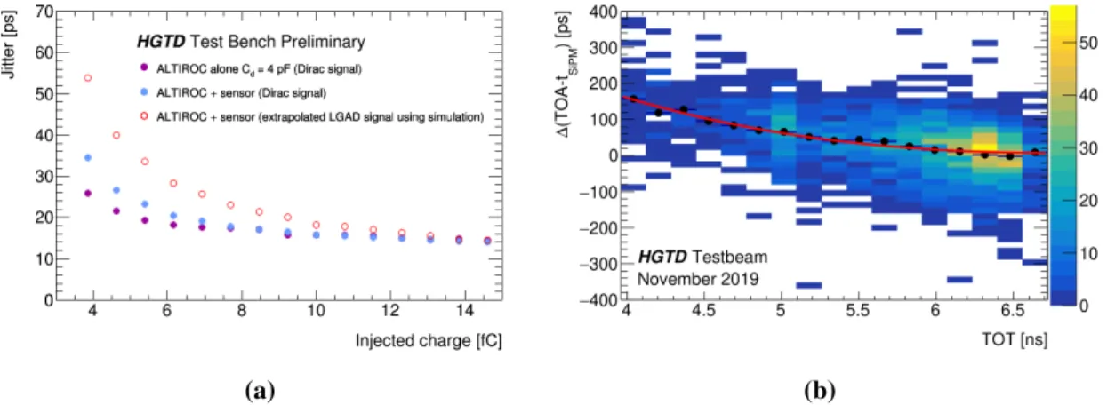
Among the prototype performances that were measured with dedicated test-benches one can mention the efficiency and the time resolution. With a 4 fC signal, the efficiency is almost at 100% with an ASIC operated alone or with the sensor equivalent capacitance. A time precision (Figure2a) better than 25 ps was measured with the ASIC alone and for a 4 fC signal. The time jitter is increased to 55 ps when the expected LGAD signal is considered. Finally, the impact of radiations on the ASIC was tested with ionizing beams. It was found that the relative degradation of the jitter is between 10% and 15% after a Total Ionizing Dose of 2 MGy.
PoS(LHCP2020)080
Particle beams were used to test sensors and bare modules, combining sensors and ASICs,during campaigns from 2016 to 2019 at CERN SPS [4] and at DESY [5]. The signal efficiency, as well as the time resolution, were measured using different LGADs irradiated at the maximal fluence [4]. The impact of the amplitude of the signal on the TOA is observed (Figure 2b) illustrating the so-called time walk effect. Correcting for this effect allows to improve the time resolution.
(a) (b)
Figure 2:Jitter (a) measured as a function of the injected charge for an ASIC alone with Cd = 4 pF (purple)
and with an ASIC bump bonded to a sensor (blue) measured with the calibration setup. Fora, the open circle
shows the jitter for an LGAD input signal estimated from the calibration data and the simulation. Distribution
of the TOA (b) as a function of the TOT. The red line is a fit of the average TOA as a function of the TOT [6].
3. Conclusion
A High-Granularity Timing Detector was designed in order to resolve the temporal spread of bunch crossing in the forward region. A technology based on LGADs and ASIC readout will be used in order to reach a precision of 30 to 50 ps up to an integrated luminosity of 4000 fb−1. Several prototype tests were performed including dedicated beam tests. The impact of using timing information on physics performance was studied. The HGTD design and foreseen performances were documented in a recently published Technical Design Report [6].
References
[1] G. Apollinari et al., High-Luminosity Large Hadron Collider (HL-LHC): Technical De-sign Report V. 0.1. CERN Yellow Reports: Monographs. CERN, Geneva, 2017, URL: https://cds.cern.ch/record/2284929
[2] ATLAS Collaboration, The ATLAS Experiment at the CERN Large Hadron Collider. JINST 3 (2008) S08003.
[3] ATLAS Collaboration, Technical Design Report for the ATLAS Inner Tracker Pixel Detector. Technical Report CERN-LHCC-2017-021. ATLAS-TDR-030, CERN, Geneva, Sep 2017, URL: https://cds.cern.ch/record/2284929
PoS(LHCP2020)080
[4] C. Allaire et al., Beam test measurements of low gain avalanche detector single pads and arraysfor the ATLAS high granularity timing detector. JINST 13 (2018) P06017.
[5] R. Diener et al., The DESY II Test Beam Facility. Nucl. Instrum. Meth. A, 922 (2019) 265–286. [6] ATLAS Collaboration, Technical Design Report: A High-Granularity Timing Detector for the ATLAS Phase-II Upgrade. Technical Report CERN-LHCC-2020-007. ATLAS-TDR-031, CERN, Geneva, Jun 2020, URL: https://cds.cern.ch/record/2719855