Application Flexibility of a Low-Loss
High-Frequency Inductor Structure
The MIT Faculty has made this article openly available.
Please share
how this access benefits you. Your story matters.
Citation
Yang, Rachel S. et al. "Application Flexibility of a Low-Loss
High-Frequency Inductor Structure." 2020 IEEE Applied Power Electronics
Conference and Exposition, March 2020, New Orleans, Louisiana,
Institute of Electrical and Electronics Engineers, June 2020. © 2020
IEEE
As Published
http://dx.doi.org/10.1109/apec39645.2020.9124502
Publisher
Institute of Electrical and Electronics Engineers (IEEE)
Version
Author's final manuscript
Citable link
https://hdl.handle.net/1721.1/130103
Terms of Use
Creative Commons Attribution-Noncommercial-Share Alike
Application Flexibility of a Low-Loss
High-Frequency Inductor Structure
Rachel S. Yang
∗, Alex J. Hanson
†, Charles R. Sullivan
‡, David J. Perreault
∗[email protected], [email protected], [email protected], [email protected]
∗
Massachusetts Institute of Technology, 77 Massachusetts Avenue, Cambridge, MA 02139, USA
†
The University of Texas at Austin, 2501 Speedway, Austin, TX 78712, USA
‡Thayer School of Engineering at Dartmouth, 14 Engineering Drive, Hanover, NH 03755, USA
Abstract—Miniaturization and improved performance of power electronics today are limited by magnetic components, which are difficult to scale to small size and high frequencies. Inductor structures using field shaping, quasi-distributed gaps, and modular construction have recently been shown to achieve low loss at HF. Nevertheless, for widespread adoption, it must be shown that such structures can continue to achieve low loss across applications and can also be produced economically. This work demonstrates that the previously-proposed inductor structure with the listed design features can cover a wide range of inductance and power handling requirements with only a few sets of manufactured core pieces. In particular, while conventional core sets are usually scaled by roughly 2x in volume, core set components for the proposed structure can be scaled by 4x in volume and still achieve high performance across a large, continuous range of inductor requirements. The proposed inductor structure and design techniques thus have potential for commercial adoption to facilitate the design of low-loss HF inductors.
I. INTRODUCTION
High-frequency operation (HF: 3–30 MHz) enables minia-turization and improved performance of power electronics. However, magnetic components suffer from fundamental scal-ing limitations [1] and high-frequency loss mechanisms with few effective mitigation techniques above 3 MHz. Neverthe-less, advancements are emerging. Some low-permeability core materials have been recently identified with low losses at HF, which has created opportunities for improving magnetics design [2], [3]. To better capitalize on these high-performance materials, core geometry design has also been investigated to mitigate copper loss, including the use of distributed gaps, field shaping, and fringing field avoidance (see e.g. [4]–[11]). To assess the use of potential core structures beyond one-time custom designs, their performance and limitations must be evaluated across a range of applications. Furthermore, to understand the potential for a proposed structure to sub-stantially impact the industry, we must evaluate how the structure scales to large production volumes and a variety of customer needs. One way to probe the economics of scaling is to consider the range of inductances and power handling capabilities1 that a single core set of a structure can cover
1This digest uses VA as the equivalent metric for power handling of sinusoidal waveforms, where VA = Vrms· Irms = (2πf λ)Irms = 2πf LI2
rms= πf LI2and I is the amplitude of the sinusoidal current.
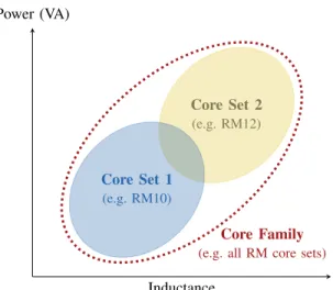
Core Set 1
(e.g. RM10)
Core Set 2
(e.g. RM12)
Core Family (e.g. all RM core sets)
Inductance Power (VA)
Fig. 1: A given core set at a given loss or thermal limit can cover a certain set of applications, represented by a range of inductances and power handling capabilities (i.e. V/A ratios and V×A products). A viable series of core sets has some overlap in “application space,” and the most economical family of core sets covers the widest area with the fewest sets.
(Fig. 1). To first order, core sets that cover a wider range of applications require manufacturing of fewer different parts and are therefore more economically viable.
In [6], a closed-core, modular inductor structure using quasi-distributed gaps and field shaping is shown to achieve a high quality factor Q in an example design (Fig. 2). Through field shaping accomplished by balancing reluctances in the core center post and return path, the structure balances the H fields on either side of a single-layer winding to achieve double-sided conduction, where the current is more evenly distributed around the circumference of the conductor. The structure’s low loss and modularity therefore make it a good candidate for covering a large application space with a small set of parts, while also providing form factor flexibility.
In this paper, we explore the application space covered by a single core set of this structure as well as scaling approaches for core set components. We demonstrate that the structure in [6] can indeed cover a wide application space, that a 4x scaling in volume is a potential approach for creating
complimentary core sets (versus 2x in conventional core sets), and that the proposed structure outperforms cores of similar volumes in the commercially produced “EQ” family at HF.
II. DESIGNFLEXIBILITY OF ASINGLECORESET
The closed-core inductor structure proposed in [6] resem-bles a pot core with a single-layer winding, but has a carefully designed center post and outer shell with quasi-distributed gaps. The core geometry of this structure consists of cylin-drical end caps and a modular stack of center discs, outer rings, and center and outer gap spacers (Fig. 2). A collection of the magnetic parts with specified dimensions is called a core set with a footprint defined by the diameter of the end cap. We denote a core set for this type of modified pot core by MPa, where a is the approximate footprint diameter in millimeters. Due to the modularity of the core set, inductors may be designed with different numbers of magnetic/spacer layers. We specify an inductor configuration that uses core set MPa by MPa/b, where b is the aspect ratio of the height to the diameter, h/D. For example, the MP27 core set has a footprint diameter of 27 mm, from which many inductors can be created. An MP27/1.0 inductor uses the MP27 core set with a stack of magnetic/spacer layers that results in a total height of 27 mm.
First, we used finite element analysis (FEA) simulation to evaluate the inductance and power handling range of the MP27 core set proposed in [6] by adjusting the number of turns in the winding, the number of discs and gaps, and the gap length. The frequency was held constant at 3 MHz, and a temperature rise constraint of ∆T ≤ 40◦C was imposed using a constant heat flux model2 [12], [13]. Modeling predictions were based on 2D cylindrical simulations in ANSYS Maxwell 19.2. The core material used was Fair-Rite 67 (a very low loss NiZn ferrite), and the winding was limited to single-strand round wire. Section III evaluates smaller and larger core sets through simulations in the same manner. Conclusions from simulation results are validated with experimental results in Section IV. A. Inductance Range. For a given core geometry, the inductance can be changed via the number of turns and/or the overall gap length. A large deviation in gap length from the optimum, however, can greatly degrade Q by shifting the copper and core loss distribution. Therefore, we focused on the inductance range achieved by only changing the number of turns (and adjusting the conductor diameter accordingly to appropriately fill the window) (Fig. 3).
The achievable inductance range of a core configuration is determined by the range in which the configuration achieves relatively constant power handling. To evaluate the power handling of a single core configuration, we first examine how its Q or loss varies across inductance at constant power. For
2This thermal model assumes that power dissipates evenly over the entire surface area of a structure and estimates temperature rise using P ≈ kA∆T , where P is the dissipated power, k is the heat transfer coefficient, A is the surface area of the structure, and ∆T is the change in temperature. Using the MP27/1.0 prototype in [6], we experimentally estimated k = 10.0 W/(m2◦C).
Fig. 2: A single core set of the MP inductor structure is composed of three types of magnetic parts: the center disc, the outer ring, and the end cap. The outer ring may be realized as a ring with a notch cut out to allow for the winding terminations to leave the structure. A stack of center discs with gap spacers form the center post, and a stack of outer rings with gap spacers form the outer shell.
Fig. 3: Core window cross-sections for different numbers of turns in a single MP core configuration. As the number of turns changes to vary the inductance, the conductor diameter is also adjusted to appropriately fill the window. For very small number of turns (left), the wire diameter is limited by the window width, leading to large vertical spacing between turns. For very large number of turns (right), the wire diameter is limited by the window height.
a constant VA (or energy storage) and fixed gap length, the loss in the MP inductor structure does not vary greatly with the number of turns across a wide inductance range. In this case, the B fields, and thus the core loss, stay fairly constant. Furthermore, in a single-layer winding, changing the number of turns also does not greatly change copper loss for constant VA. While the conductor resistance (R) roughly scales as N2
with inductance, the current (i) scales as 1/N for constant peak energy storage, leading to the two factors roughly cancelling in i2R power loss. For single-strand round wire, this constant performance drops off for very small N , as the window width restricts the wire diameter for poor vertical window utilization, and for very large N , as winding resistance scales faster than N2for wire diameters approaching the skin depth. However, a
different wire type, e.g. oval or rectangular, could extend this constant performance region.
The fidelity of this analysis was demonstrated with the MP27/1.0 core configuration3 from [6], which is 16.6 µH
with 13 turns, at the maximum allowable temperature rise ∆T = 40◦C. Fig. 4 plots the inductance range for the constant performance region of the MP27/1.0 core using single-strand round wire. At a high power handling threshold of∼1000 VA, this core configuration can cover a factor-of-50 range of inductances for < 10 % variation in maximum power handling. For larger variation, an even greater inductance range can be achieved. Since the performance across inductances is not specific to this configuration, we can expect a similarly wide coverage of inductances for other configurations, as confirmed in later sections.
B. Power Handling Range. For a given MP core set, the volume of the inductor structure, and thus its power handling capability, can be changed with relatively fine granularity via the number of stacked core pieces in the center post and outer shell. The aspect ratio (h/D) of the structure also scales linearly with volume.
To evaluate the power handling range of the MP27 core set, structures with different aspect ratios (and volumes) were simulated with FEA across a range of inductances within the temperature rise constraint ∆T ≤ 40◦C (Fig. 5). The plotted region in Fig. 5 represents the range of applications that the MP27 core set can reasonably cover. Varying the number and diameter of the turns allows each core configuration to cover a wide range of inductances with high performance, as predicted in Section II-A. Larger inductors (taller aspect ratios for a given footprint) can also process more power. For a reasonable range of aspect ratios (0.4 ≤ h/D ≤ 3.0), the core set can accommodate nearly a factor of 10 in power at ∆T = 40◦C using only three distinct parts. The lower bound of this range (h/D = 0.4) is set by the height of two stacked core pieces with a single gap, while the upper bound (h/D = 3.0) is set by practical considerations of desired inductor shapes.
III. APPROACHES FORCONSTRUCTING ANECONOMICAL ANDHIGH-PERFORMANCEMP CORESETFAMILY
Next, we used FEA simulation to explore approaches for scaling MP core set sizes in the same way that conventional cores are scaled to yield a core family, e.g. RM10, RM12, RM14, etc. These scaling approaches should economically cover a wide application space with a few core sets and also maintain high performance across applications. For continuous coverage, adjacent core set sizes should also have an overlap in achievable application space.
To determine appropriate scaling approaches, we consider how the MP inductor structure’s performance changes across aspect ratios. As shown in [6], for a single design at a given volume, the MP structure achieves optimum Q at an aspect ratio of h/D ≈ 1, with Q falling off slowly from this optimum.
3For geometry specifications of the simulated inductors in this paper, see Appendix A. For Fair-Rite 67, the Steinmetz parameters used in simulations at 3 MHz were kc= 0.034, α = 1.18, and β = 2.24 (for Pvin mW/cm3, f in MHz, ˆB in mT), which were derived using core loss data from [2].
Power (VA) 100 101 102 103 103 Inductance (µH)
MP27
h/D = 1.0Fig. 4: Simulated maximum power handling curve at ∆T = 40◦C and 3 MHz of the MP27/1.0 configuration. The range of achievable inductor requirements is the area underneath this curve. The config-uration can cover a factor-of-50 range of inductances at∼1000 VA.
100 101 102 103 102 103 Inductance (µH) 3.0 2.0 1.0 0.5 0.4 Power (VA) h/D
MP27
Fig. 5: Simulated maximum power handling curves at ∆T = 40◦C and 3 MHz of the MP27 core set at various aspect ratios. The power handling of the structure scales with aspect ratio (or volume) by changing the number of stacked core pieces in the center post and outer shell. For the plotted range of aspect ratios, this core set can achieve a factor-of-10 range in power handling. Each curve also achieves a wide inductance range.
Furthermore, within a given core set, the additional constraint of fixed core piece geometries also degrades Q for h/D 6= 1 because the structure no longer achieves field balancing for sided conduction in the winding. To achieve double-sided conduction, the structure should balance the reluctances in the center post and return path (outer shell and fringing field). As the number of stacked core pieces changes to achieve different aspect ratios, the reluctances in the center post and outer shell scale similarly. However, the fringing field reluctance (Rf ringe≈ 0.9/(µ0πrt)) is fixed by the footprint of
the core set and is not significantly affected by the height [14]. For symmetric core stacking in the center post and outer shell, the reluctances in the center post and return path thus cannot remain balanced, leading to field imbalance and loss of double-sided conduction.
Therefore, the MP core set family with the greatest perfor-mance (at the expense of cost) would be solely composed of MP core configurations with h/D = 1. For a more
TABLE I: Geometry of Various MP Core Sets
MP17 MP21 MP27 MP33 MP42 Volume Scale Factor 0.25 0.5 1.0 2.0 4.0 Total Diameter 16.75 mm 21.1 mm 26.9 mm 33.5 mm 42.2 mm Center Post Radius 5.75 mm 7.2 mm 9.9 mm 12.0 mm 15.5 mm Window Width 1.2 mm 1.65 mm 1.4 mm 1.7 mm 2.1 mm End Cap Height 2.5 mm 3.0 mm 4.0 mm 5.0 mm 6.0 mm Core Disc/Ring Height 0.83 mm 1.16 mm 1.18 mm 1.18 mm 1.46 mm
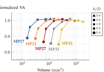
Normalized VA h/D 103 104 105 0.6 0.8 1.0 Volume (mm3) 3.0 2.0 1.0 0.5 0.4 MP17 MP21 MP27 MP33 MP42
Fig. 6: Simulated normalized power handling curves4for various MP
core sets at ∆T = 40◦C and 3 MHz across different aspect ratios. For h/D ≥ 1, each core set has roughly optimum power handling capability. For h/D < 1, the performance drops off slowly, with the smallest aspect ratio h/D = 0.4 still achieving ∼70 % of the
optimum VA.
economical MP core set family, however, core set footprints should be scaled only when a core set greatly underperforms the adjacent core set, i.e. when the tallest inductor from a core set is outperformed by the shortest inductor of the next largest core set. To evaluate this, we compared the simulated power handling performance of different MP core sets at 3 MHz, normalized to the optimum power handling4, across
a reasonable range of aspect ratios (0.4 ≤ h/D ≤ 3.0). The different core set footprints were scaled in volume from the MP27/1.0 configuration, with each dimension scaled equally (Table I). For example, a core set footprint is scaled by 4x in volume if its h/D = 1.0 configuration is 4x the volume of the MP27/1.0 configuration, with the volume of inductors in both core sets varying with h/D.
As shown in Fig. 6, each MP core set performs near optimum for aspect ratios h/D ≥ 1. While the Q of the MP structure deviates from optimum for h/D > 1, taller structures can better dissipate heat, as their surface area to volume ratio is larger than that of a structure with a “square” aspect ratio (h/D = 1). Thus, for a constant temperature rise constraint, MP structures can continue to perform near optimum for large aspect ratios.
4The optimum power handling at 3 MHz was determined using a curve fit of simulated VA handling of MP inductors at h/D = 1 and ∆T = 40◦C for volumes ranging from 1800 mm3to 118 000 mm3.
For h/D < 1, the performance of each core set begins to drop off. For shorter structures in a core set, the Q falls from optimum more quickly than the surface area to volume ratio increases. Since the end cap heights in each core set are fixed, shorter structures have less volume for the “active” section, where flux links the winding, which degrades the Q. However, the drop-off in power handling performance is relatively slow. Even at the smallest possible aspect ratio h/D = 0.4, composed of two core pieces with a single gap, the performance is still at least∼70 % of the optimum VA.
A. Factor-of-Four Volume Scaling. From Fig. 6, an eco-nomical and high-performance MP core family could be composed of core sets that span an aspect ratio range from h/D = 0.5 to h/D = 2.0, with adjacent core sets overlap-ping in volume at these boundaries. Such a MP core family corresponds to core set footprints being scaled by 4x in volume (with each dimension scaled equally), e.g. MP17, MP27, and MP42 in Fig. 6. At h/D = 0.5, MP core sets maintain high performance at∼90 % of the optimum VA. Additionally,
while core sets can continue to handle near optimum VA at ∆T = 40◦C for much higher aspect ratios, structures taller than h/D = 2.0 become undesirable in terms of shape and achievable Q.
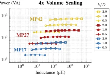
Scaling MP core set footprints by 4x in volume covers a wide application space (Fig. 7). Three adjacent core sets can cover at least three orders of magnitude in inductance and a factor-of-45 in maximum power handling. Furthermore, at the overlap regions between core sets (MP17/2.0 and MP27/0.5, MP27/2.0 and MP42/0.5), adjacent core sets have comparable performance for similar volume, allowing for some form factor flexibility. Height-constrained designs can use larger footprint core sets with smaller aspect ratios, while footprint-constrained designs can use smaller footprint core sets with taller aspect ratios.
B. Factor-of-Two Volume Scaling. MP core set components could alternatively be scaled by 2x in volume, as is done with typical industry-standard closed cores, e.g. RM or pot cores [15], [16]. Doing so would require more distinct parts but would achieve greater overlap between core sets for greater form factor flexibility. Fig. 8 plots three core sets with footprints scaled by 2x in volume: MP21, MP27, and MP33 from Fig. 6. With this scale factor, three adjacent core sets only cover a factor-of-15 in power handling. However, any given volume has at least two form factor options, one at a smaller footprint with taller aspect ratio and one at a larger
100 101 102 103 104 102 103 104 Inductance (µH) 2.0 1.0 0.5 2.0 1.0 0.5 2.0 1.0 0.5
4x Volume Scaling
MP42
MP27
MP17
Power (VA) h/DFig. 7: 4x Volume Scaling: Simulated maximum power handling curves at ∆T = 40◦C and 3 MHz of the MP17 (blue), MP27 (red), and MP42 (yellow) core sets at various aspect ratios. The three core sets cover a wide range of inductor requirements, while still having overlaps in performance.
footprint with shorter aspect ratio. At the volume of MP27/1.0, two additional form factors exist, MP21/2.0 and MP33/0.5, for a total of three form factors.
IV. EXPERIMENTALRESULTS FOR THEMP17ANDMP27 CORESETS
We validated the simulated performance of the MP17 and MP27 core sets at 3 MHz with four inductor prototypes: MP17/1.0, MP17/2.0, MP27/0.5, and MP27/1.0 (Table II, Fig. 9), i.e. two designs at the optimal aspect ratio (∼1.0) [6]
and two designs of similar volume but different footprint.5
The use of litz wire to improve the Q of these prototypes was also demonstrated. For comparison to industry-standard cores, inductors made from the commercial EQ core series with sim-ilar volumes were built and were substantially outperformed by the MP inductor prototypes.
A. Q Measurements Validate Simulations. Using the res-onant measurement approach for high Q from [6],6 large-signal Q measurements of the four inductor prototypes were taken at their respective maximum VA level for a simu-lated ∆T = 40◦C. For each VA level, the inductor was operated at a current corresponding to the desired VA, i.e. I = pVA/(πfL). The measured quality factors of the four prototypes agreed with the simulated ones (Table III). The MP17/2.0 and MP27/0.5 inductors, which have the same volume, also had comparable measured quality factors (within 15 % of each other), verifying an overlap in performance between the two core sets.
5The prototypes were built using the same construction process as in [6], except the outer shell for the MP17 prototypes was constructed from a single stack of outer rings (see Fig. 2) instead of three stacked sections as done in [6].
6This measurement approach operates a series LC circuit at resonance to estimate the Q of the inductor. To more accurately measure high Q at HF, the approach compensates for loss in the capacitor ESRs and uses a capacitor divider to minimize probe loss and loading.
100 101 102 103 104 102 103 104 Inductance (µH) 2.0 1.0 0.5 2.0 1.0 0.5 2.0 1.0 0.5
2x Volume Scaling
MP33
MP27
MP21
Power (VA) h/DFig. 8: 2x Volume Scaling: Simulated maximum power handling curves at ∆T = 40◦C and 3 MHz of the MP21 (orange), MP27 (red), and MP33 (grey) core sets at various aspect ratios. Compared to 4x volume scaling (Fig. 7), these three core sets cover a smaller range of inductor requirements, but have larger overlap regions for greater form factor flexbility.
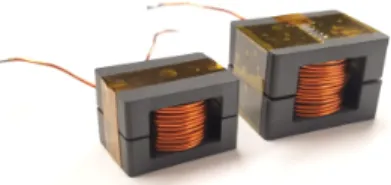
Fig. 9: Inductor prototypes with core configurations (left to right): MP17/1.0, MP17/2.0, MP27/0.5, MP27/1.0.
TABLE II: Specifications for Solid-Wire MP Inductor Prototypes Core L # of Core Total Gap N Wire
Pieces Length Gauge MP17/1.0 8.1 µH 13 0.96 mm 12 22 AWG MP17/2.0 15.7 µH 31 3.00 mm 25 22 AWG MP27/0.5 16.7 µH 4 0.60 mm 9 27 AWG MP27/1.0 13.8 µH 14 2.08 mm 13 20 AWG TABLE III: Simulated and Measured Results of MP17 and MP27 Inductors at 3 MHz for Prototypes Described in Table II
Core L (sim) L (meas) VA Q (sim) Q (meas) MP17/1.0 8.1 µH 6.8 µH 280 520 520 MP17/2.0 15.7 µH 12.9 µH 520 590 590 MP27/0.5 16.7 µH 15.8 µH 520 570 500 MP27/1.0 13.8 µH 13.4 µH 910 680 690
B. Experimental Power Handling Capabilities Exceed Simulations. The four prototype inductors were tested at ∆T = 40◦C, achieved by adjusting the large-signal excitation amplitude.7As shown in Fig. 10, the power handling exceeded
that predicted by the simulations, which used an approximate
740◦C was the surface temperature of the inductors, based on the average temperature measurement using a FLIR E6 thermal camera at different angles.
100 101 102 103 102 103 Inductance (µH) 1.0 (meas) 1.0 (sim) 0.5 (meas) 0.5 (sim) 2.0 (meas) 2.0 (sim) 1.0 (meas) 1.0 (sim)
MP27
MP17
Power (VA) h/DFig. 10: 4x Volume Scaling: Experimental power handling capability of the prototype inductors (yellow) at ∆T = 40◦C and 3 MHz compared to simulated results of the MP17 (blue) and MP27 (red) core sets. The prototype inductors achieved greater power handling than simulations using an approximate constant heat flux model. Both core sets experimentally achieved similar power handling at the same volume (MP17/2.0 vs. MP27/0.5), agreeing with simulations. TABLE IV: Measured Results of MP17 and MP27 Inductors with Litz Wire at 3 MHz Core Wire L VA Q MP17/1.0 180/48 litz 6.8 µH 280 700 MP17/2.0 300/48 litz 13.5 µH 520 780 MP27/0.5 100/48 litz 15.5 µH 520 610 MP27/1.0 450/48 litz 12.6 µH 910 960
constant heat flux model. These results suggest that for 4x volume scaling, adjacent core sets could have even greater overlap regions than simulations indicate for greater form factor flexibility. The MP17 and MP27 core sets also had comparable performance (within 7%) at the same volume, corresponding to MP17/2.0 and MP27/0.5, thus verifying an overlap in performance between the two core sets. This experimental validation suggests that a 4x volume scaling factor may be effective for covering a wide range of inductor requirements with a restricted number of core sets.
C. Litz Wire Can Improve Performance of MP Inductors. Litz wire versions of all four MP inductor prototypes were constructed using the same core geometry and number of turns as the solid-wire prototypes (Table II). Strands of 48 AWG were used, as this wire gauge is a good balance between cost and power loss at 3 MHz. The optimum number of strands for each inductor was determined using the simplified design method for litz wire [17] to roughly estimate power loss. Readily available litz wire near the optimum design that fit in the core window was then used.
At 3 MHz, litz wire improved the Q of the MP prototypes by ∼20–50 % (Table IV). The MP27/0.5 prototype had less improvement in Q with litz compared to the improvements in the other prototypes because the overall wire diameter was greatly restricted by the window height, leading to poor horizontal window utilization. Nevertheless, the improvements
Fig. 11: Inductors built using the commercial EQ core series (left to right): EEQ20/13, EEQ25/16.
TABLE V: Specifications for EEQ Inductors Core L Gap Length N Wire EEQ25/16 16.5 µH 0.66 mm 14 22 AWG solid EEQ25/16 16.1 µH 0.66 mm 14 180/48 litz EEQ20/13 7.8 µH 0.51 mm 11 22 AWG solid EEQ20/13 7.7 µH 0.51 mm 11 180/48 litz TABLE VI: Measured Results of EEQ and MP Inductors with Solid Wire at 3 MHz Core Wire L Q 7400 mm3 520 VA EEQ25/16 solid 16.5 µH 280 MP27/0.5 solid 15.8 µH 500 MP17/2.0 solid 12.9 µH 590 3700 mm3 EEQ20/13 solid 7.8 µH 270 280 VA MP17/1.0 solid 6.8 µH 520 TABLE VII: Measured Results of EEQ and MP Inductors with Litz Wire at 3 MHz Core Wire L Q 7400 mm3 520 VA EEQ25/16 litz 16.1 µH 340 MP27/0.5 litz 15.5 µH 610 MP17/2.0 litz 13.5 µH 780 3700 mm3 EEQ20/13 litz 7.7 µH 370 280 VA MP17/1.0 litz 6.8 µH 700
in Q for all four prototypes suggest that even lower loss inductor designs can be achieved by utilizing both litz wire and the MP inductor structure.
D. MP Core Set Performs Better Than EQ Core Set. To compare with industry-standard core sets, we designed inductors using EQ cores of the same core material, Fair-Rite 67 (Fig. 11). Two EQ core sizes were chosen: EEQ25/16 (25 mm long, 16 mm tall), which has the same core volume as MP17/2.0 and MP27/0.5, and EEQ20/13, which has the same core volume as MP17/1.0. Both solid-core and litz wire designs were built using these two EQ core sizes (Table V). The designs were roughly optimized using a MATLAB script that modeled core loss with the Steinmetz equation [18] and winding loss with Dowell’s equation [19]. For the litz wire designs, the optimum number of strands for 48 AWG litz was determined using the online LitzOpt software [20], based on the algorithm described in [21]. Readily available litz wire near the optimum design was then used. The EQ inductors
were gapped in the center post and the outer legs, and the windings were centered in the window to reduce fringing field loss from the gaps.
As shown in Tables VI and VII, the proposed MP inductors achieved significantly higher Q than the EQ inductors at each design volume for both solid wire and litz wire designs. With solid wire, the MP prototypes improved Q by at least 1.8x compared to EQ inductors at the same volume. With litz wire, MP inductors also achieved at least 1.8x increase in Q compared to EQ inductors at the same volume. At a given volume, the solid-wire MP inductors even substantially outperformed EQ inductors using litz wire.
V. CONCLUSION
The MP inductor structure, previously proposed in [6], has great design and application flexibility, making it a potential solution for low-loss high-frequency inductor design. Many different structures can be constructed from a single core set by changing the number of stacked core pieces in the center post and outer shell. A wide range of inductor requirements can thus be achieved from a small number of core set components. One possible approach to sizing MP core sets is to scale footprints to achieve 4x scaling in volume; this yields large, continuous coverage of requirements at low loss. With this approach, the proposed structure and design techniques have potential for commercial adoption to facilitate the design of low-loss HF inductors.
ACKNOWLEDGMENT
This work was supported in part by the National Science Foundation under Grant 1609240 and by the Cooperative Agreement between the Masdar Institute of Science and Tech-nology (Masdar Institute), Abu Dhabi, UAE and the Mas-sachusetts Institute of Technology (MIT), Cambridge, MA, USA - Reference 02/MI/MIT/CP/11/07633/GEN/G/00.
The authors would like to thank Fair-Rite for manufacturing the magnetic core pieces used in the prototypes.
APPENDIXA
GEOMETRYSPECIFICATIONS OFSIMULATEDINDUCTORS
Tables VIII–XII include geometry details for all simulated inductors in this paper. The inductors were simulated at 3 MHz with Fair-Rite 67 (µr = 40) core material. Dimensions for
each MP core set are listed in Table I.
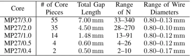
TABLE VIII: Geometry for Simulated MP27 Core Set Inductors in Fig. 4, 5, 6, 7, 8 and 10
Core # of Core Total Gap Range Range of Wire Pieces Length of N Diameters MP27/3.0 55 7.00 mm 33–340 0.80–0.13 mm MP27/2.0 35 4.50 mm 28–270 0.80–0.10 mm MP27/1.0 14 1.48 mm 13–91 0.80–0.12 mm MP27/0.5 4 0.60 mm 4–26 0.80–0.12 mm MP27/0.4 2 0.50 mm 2–10 0.80–0.17 mm
TABLE IX: Geometry for Simulated MP17 Core Set Inductors in Fig. 6, 7, and 10
Core # of Core Total Gap Range Range of Wire Pieces Length of N Diameters MP17/3.0 50 3.40 mm 29–133 0.64–0.20 mm MP17/2.0 31 2.70 mm 18–140 0.64–0.12 mm MP17/1.0 13 0.91 mm 9–63 0.64–0.11 mm MP17/0.5 4 0.40 mm 4–16 0.64–0.14 mm MP17/0.4 2 0.26 mm 2–8 0.58–0.15 mm TABLE X: Geometry for Simulated MP21 Core Set Inductors in Fig. 6 and 8
Core # of Core Total Gap Range Range of Wire Pieces Length of N Diameters MP21/3.0 45 5.20 mm 27–250 1.00–0.14 mm MP21/2.0 29 3.10 mm 15–175 1.00–0.13 mm MP21/1.0 12 2.35 mm 8–80 1.00–0.11 mm MP21/0.5 4 0.40 mm 4–22 0.76–0.14 mm MP21/0.4 2 0.50 mm 3–10 0.56–0.17 mm TABLE XI: Geometry for Simulated MP33 Core Set Inductors in Fig. 6 and 8
Core # of Core Total Gap Range Range of Wire Pieces Length of N Diameters MP33/3.0 68 10.5 mm 33–250 1.00–0.22 mm MP33/2.0 42 7.40 mm 27–280 1.00–0.12 mm MP33/1.0 18 2.21 mm 13–120 1.00–0.12 mm MP33/0.5 5 0.90 mm 5–27 0.82–0.15 mm MP33/0.4 2 0.65 mm 3–14 0.60–0.13 mm TABLE XII: Geometry for Simulated MP42 Core Set Inductors in Fig. 6 and 7
Core # of Core Total Gap Range Range of Wire Pieces Length of N Diameters MP42/3.0 70 14.0 mm 47–340 1.00–0.21 mm MP42/2.0 44 8.50 mm 31–280 1.00–0.16 mm MP42/1.0 18 3.94 mm 17–140 1.07–0.13 mm MP42/0.5 5 1.40 mm 5–29 1.00–0.18 mm MP42/0.4 2 1.00 mm 3–20 0.78–0.12 mm REFERENCES
[1] C. R. Sullivan, B. A. Reese, A. L. F. Stein, and P. A. Kyaw, “On size and magnetics: Why small efficient power inductors are rare,” in 2016 International Symposium on 3D Power Electronics Integration and Manufacturing (3D-PEIM), June 2016, pp. 1–23.
[2] A. J. Hanson, J. A. Belk, S. Lim, C. R. Sullivan, and D. J. Perreault, “Measurements and performance factor comparisons of magnetic materi-als at high frequency,” IEEE Transactions on Power Electronics, vol. 31, no. 11, pp. 7909–7925, Nov 2016.
[3] Y. Han, G. Cheung, A. Li, C. Sullivan, and D. Perreault, “Evaluation of magnetic materials for very high frequency applications,” IEEE Transactions on Power Electronics, pp. 425–435, 2008.
[4] Z. Ouyang and M. A. E. Andersen, “Overview of planar magnetic technology—fundamental properties,” IEEE Transactions on Power Electronics, vol. 29, no. 9, pp. 4888–4900, Sep. 2014.
[5] S. Lu, C. Ding, Y. Mei, K. D. T. Ngo, and G. Lu, “Hetero-magnetic coupled inductor (HMCI) for high frequency interleaved multiphase dc/dc converters,” in 2019 IEEE Applied Power Electronics Conference and Exposition (APEC), March 2019, pp. 2667–2672.
[6] R. S. Yang, A. J. Hanson, B. A. Reese, C. R. Sullivan, and D. J. Perreault, “A low-loss inductor structure and design guidelines for high-frequency applications,” IEEE Transactions on Power Electronics, vol. 34, no. 10, pp. 9993–10 005, Oct 2019.
[7] J. Hu and C. R. Sullivan, “The quasi-distributed gap technique for planar inductors: design guidelines,” in Industry Applications Conference, 1997. Thirty-Second IAS Annual Meeting, IAS ’97., Conference Record of the 1997 IEEE, vol. 2, Oct 1997, pp. 1147–1152 vol.2.
[8] EPCOS AG – a TDK Group Company, “Distributed air gaps in ferrite cores,” June 2017. [Online]. Available: https://de.tdk.eu/download/ 2113422/321697054fce0c768ea66959fde3b3db/ferrites-air-gaps-pb.pdf [9] Y. Cai, M. H. Ahmed, Q. Li, and F. C. Lee, “Optimized design of
integrated pcb-winding transformer for MHz LLC converter,” in IEEE Applied Power Electronics Conference and Exposition (APEC), March 2019, pp. 1452–1458.
[10] J. Sch¨afer, D. Bortis, and J. W. Kolar, “Optimal design of highly efficient and highly compact pcb winding inductors,” in 2018 IEEE 19th Workshop on Control and Modeling for Power Electronics (COMPEL), June 2018, pp. 1–8.
[11] S. Mukherjee, Y. Gao, R. Ramos, V. Sankaranarayanan, B. Majmunovic, R. Mallik, S. Dutta, G. Seo, B. Johnson, and D. Maksimovic, “Ac resis-tance reduction using orthogonal airgaps in high frequency inductors,” in 2019 IEEE Workshop on Control and Modeling of Power Electronics (COMPEL), June 2019.
[12] D. J. Perreault, J. Hu, J. M. Rivas, Y. Han, O. Leitermann, R. C. N. Pilawa-Podgurski, A. Sagneri, and C. R. Sullivan, “Opportunities and challenges in very high frequency power conversion,” in 2009 Twenty-Fourth Annual IEEE Applied Power Electronics Conference and Expo-sition, Feb 2009, pp. 1–14.
[13] J. Hu, “Design of low-voltage, high-bandwidth radio frequency power converters,” Ph.D. dissertation, Massachusetts Institute of Technology, 2012.
[14] T. H. Lee, Planar Microwave Engineering: A Practical Guide to Theory, Measurement, and Circuits, 1st ed. Cambridge University Press, 2004, pp. 140–142.
[15] TDK, “Mn-Zn ferrite cores for switching power supplies, RM series,” May 2019. [Online]. Available: https://product.tdk.com/info/en/catalog/ datasheets/ferrite mz sw rm en.pdf
[16] Magnetics, “Ferrite pot cores,” May 2019. [Online]. Available: https: //product.tdk.com/info/en/catalog/datasheets/ferrite mz sw rm en.pdf [17] C. R. Sullivan and R. Y. Zhang, “Simplified design method for litz wire,”
in IEEE App. Pow. Electr. Conf. (APEC), 2014, pp. 2667–2674. [18] C. P. Steinmetz, “On the law of hysteresis,” Transactions of the American
Institute of Electrical Engineers, vol. IX, no. 1, pp. 1–64, Jan 1892. [19] P. L. Dowell, “Effects of eddy currents in transformer windings,”
Electrical Engineers, Proceedings of the Institution of, vol. 113, no. 8, pp. 1387–1394, August 1966.
[20] C. R. Sullivan, T. Abdallah, and J. Pollock, “Litzopt,” October 2019. [Online]. Available: http://power.thayer.dartmouth.edu/litzopt init web. html
[21] C. R. Sullivan, “Computationally efficient winding loss calculation with multiple windings, arbitrary waveforms, and two-dimensional or three-dimensional field geometry,” IEEE Transactions on Power Electronics, vol. 16, no. 1, pp. 142–150, Jan 2001.