Design of Soft-Body Robot with Wireless Communication for Leak Detection in
Large Diameter Pipe Systems
by
Kyle Scott Saleeby
Submitted to the
Department of Mechanical Engineering
in Partial Fulfillment of the Requirements for the Degree of Bachelor of Science in Mechanical Engineering
at the
Massachusetts Institute of Technology
June 2017 MASSACHUSETTS INSTITUTE OF TECHNOLOGY
JUL 25 2017
LIBRARIES
Signature of Author:ARCHIVES
C 2017 Massachusetts Institute of Technology. All rights reserved.
Signature redacted
Certified by:
Accepted by:
6'Department of Mec1fnical Engineering
May 1 2 th 2017
Signature redacted
Kamal Youcef-Toumi Professor of Mechanical Engineering Thesis Supervisor
Signature redacted
Rohit Karnik Associate Professor of Mechanical Engineering Undergraduate Officer
Design of Soft-Body Robot with Wireless Communication for Leak Detection in Large Diameter Pipe Systems
by
Kyle Scott Saleeby
Submitted to the Department of Mechanical Engineering on May 1 2th, 2017 in Partial Fulfillment of the
Requirements for the Degree of
Bachelor of Science in Mechanical Engineering
ABSTRACT
Water leaks pose a major problem of efficiency and cost to municipalities and industries that cover significant area. While current commercial methods to address these problems do not provide convenient or low cost methods to detect leaks, a soft-body pipe leak detection robot has been developed to traverse small, 50mm diameter water pipe systems. This robot has proven to be effective in small diameter pipes, but its scalability for large diameter pipes is unknown. The focus of this thesis is to scale up the leak detection robot for 300mm diameter pipes and fabricate a robot prototype. In particular, the relationship between the shape of the robot and its maneuverability was explored, such that it was designed to passively travel through the pipe, driven by water flow. The robot was designed to successfully pass through changes in pipe diameter, pipe bends, and through partially clogged regions. To detect and distinguish pipe leaks from other debris in the pipe, two sensors were integrated in the robot. Experimental testing was conducted with the robot to verify functionality of its leak detection sensors. Supporting
electronics were also implemented to wirelessly charge and communicate with the robot. Thesis Supervisor: Kamal Youcef-Toumi
Tile: Professor of Mechanical Engineering
I would like to respectfully thank You Wu for his endless support, patient explanations, and engineering wisdom, as well as Professor Kamal Youcef-Toumi for his guidance and for generously giving me the opportunity to join an incredible research team and complete this project. Finally, to my mother, my father, my grandmother, and friends for their loving support.
Thank you.
Table of Contents
A b stra ct...2
1. Background and Motivation...5
2. Mechanical Design and Scaling...6
2.1 Design Needs and Constraints...6
2.2 Soft Body and Maneuverability ... 8
2.3 Leak Detection Membrane Sensor...11
2.4 Leak Sensor Mount...13
2.5 Sensor Arm and Position Encoder...14
2 .6 S ensor H ub ... 16
3. Electrical Design and Communication...17
3.1 Microcontroller Framework - Intel Edison...17
3.2 Data Acquisition and Logging...18
3.3 Wireless Communication... 19
3.4 Power Requirements...20
3.5 Wireless Charging...20
4. Fabrication and Assembly ... 22
4.1 Fabrication of Rigid Parts...22
4.2 Fabrication of Membrane Sensors...22
4.3 Assembly of Membrane Mounts...23
4.4 Fabrication of Molds and Design Changes...24
4.5 Assembly of Sensor Arm and Position Encoder...27
4.6 Molding the Soft Body ... 28
5. Experimental Testing... 30
5.1 Verification of Membrane Sensor...30
5.2 Verification of Arm Sensor...33
1. Background and Motivation
It's estimated that up to 20% of the world's clean water is lost while traveling through distribution networks.' While major pipe failures cause disastrous floods, other small leaks may also cause significant water loss over time. These smaller breaches are not usually detected until they become large enough to damage surrounding infrastructure. Our leak detection robot must be able to detect and determine the relative size of leaks such that both small and large leaks can be identified and repaired before causing damage.
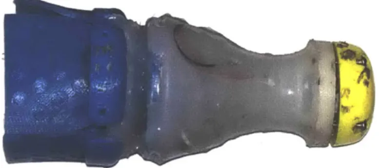
Figure 1: A leak detection robot created by You Wu et. al. for use in 50mm diameter pipes. The robot successfully distinguishes between true leaks and false-positive detections.
A leak detection sensor and transportation robot displayed in Figure 1 was created by
You Wu et. al. in MIT's Mechatronics Research Laboratory to address this problem for 50mm diameter pipes.2 While this method was proven effective at detecting and distinguishing leaks from false alarms, the robot was limited to a single pipe diameter.
We aim to build upon the initial research and create a robot to detect leaks in large diameter pipes. Many techniques from the original system can be further developed and tested at a larger scale. Other methods of data acquisition and false-positive detection exclusion must be re-evaluated at this scale.
Vickers A. L., "The future of water conservation: Challenges ahead," Water Resources Update, Universities Council on Water Resources, Tech. Rep., 1999.
2 You Wu, Solene Demay and Kamal Youcef-Toumi, "Design of a Soft-Body Drone for Missions in Small Diameter Water Pipe Systems", IROS 2017, under review.
5
2. Mechanical Design and Scaling
2.1 Design Needs and Constraints
Our leak detection robot must be designed to work in a much larger 300 mm pipe diameter. The initial robot was designed to work in a pipe 50 mm in diameter, but we cannot simply scale each dimension to match a larger pipe. Each part must be evaluated and designed to account for adverse effects at this scale. The robot is comprised of eight parts; The soft body, hard body armor and cap, membrane sensors, membrane mount, sensor arm and position encoder, and sensor hub.
Our device must:
* Passively travel through 300mm dia. pipes and pipe bends, driven by water flow. " Detect the relative size of leaks and identify false-positive detections from debris.
" Communicate and charge wirelessly, completely sealed from the environment.
Many water pipes in the world's infrastructure are not in good condition. Water pipe networks often suffer from partial clogs due to contamination buildup, corrosion, and gradual shifts in placement. Metal pipes in the United States are particularly prone to corrosive effects, increasing the risk of contamination and buildup. While plastic pipes in other countries may not suffer from corrosion to the same extent, similar problems of buildup and clogs are still present. Additionally, pipes within the system intersect at varying angles (typically obtuse) and may experience changes in diameter at different points. Our device must be able to travel through regions with partial clogs and moderate changes in pipe diameter without getting stuck. Our leak detection device must be able to pass through pipe intersections of right or obtuse angles,
passively navigating turns without active changes to its shape or ill effects on its leak detection
capabilities. Our device must also be durable to withstand the abrasive inner walls and sharp joints within a pipeline system.
Our robot must be designed such that it can reliably detect leaks while passively
travelling with the flow of the water. We assume a maximum velocity of flow in pipes to be 0.6 m/s and assume that our detection method will be sufficient for lower velocities as well.
Our device also must be completely sealed and waterproof. Electrical failure due to shorts is extremely likely in this environment, and any ports or openings to access the electronics only increase the risk of failure. All functionality of our device must be accessible through non-contact methods.
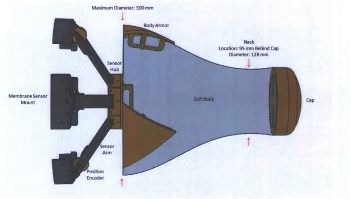
Maximum Diameter: 300 mm
BdArmor
Neck
Location: 95 mm Behind Cap
Diameter: 128 mr
Sensor
Hub
Membrane Sensor SoftBod
Cap MountCp
Snsor Arm
Encoder
Figure 2: Model of 300mm diameter Pipe Leak detection robot, without membrane sensors. A neck is placed approximately 95
2.2 Soft Body and Maneuverability The leak detection robot must be able
to successfully pass through pipe bends Pipe Pipe
\PPePipe
greater-than or equal to 900 angles without > 900
getting stuck. Most pipes do not bend at angles <909 less than 90', displayed in Figure 3, and we do
not consider them.
Figure 3: The leak detection robot must successfully pass Soft body robotics provide an elegant through pipes bends of angles greater-than or equal to 90. solution for this constraint. Using flexible materials in structural locations is an unintuitive development that bends traditionally rigid design constraints. We can exploit soft materials in structural locations to create a body for the robot that passively adapts to its environment.
We designed the body to bend at a point approximately 96mm behind the tip of the cap (labeled distance AB) to passively bend through pipe turns. The cross sectional diameter at this
Cap TCap Apex
point was gradually reduced to 128mm, creating Center of Curvature a neck as depicted in Figure 2. The diameter
reduction is not significant in this case, but it is
'Minimum Wjdth
Neck Location
sufficient for the robot to bend. If the diameter
Figure 4: The cap's center of curvature was designed to fall behind the minimum neck width, inducing the robot's head to reduction was more significant, the neck may be bend with a curve in the pipe system.
too weak and unable to induce the robot to turn in the desired way. Regions above this neck will bend around turns as the robot is driven by existing water flow. Additionally, the orange cap of the robot illustrated in Figure 4 was designed such that the center of curvature fell laterally
behind the minimum neck width. After impacting the inner wall on a turn, the cap's large radius of curvature, and more importantly, the placement of its center induces the "head" of the robot to bend in a direction following the turn. A curvature whose center is placed in front of the neck creates a resultant force that opposes the forward motion of the robot instead of allowing the head to glance away and bend in the direction of the curve. After the head bends about the neck, the body of the robot follows as water pressure pushes it through the curve.
The body of our leak detection robot was designed to work in a 300mm diameter pipe. Pipes used to transport water are not consistent in size throughout the system, and our robot must work within a range of dimension around the nominal diameter. The nominal outer diameter of the robot was designed to be 304mm, 4mm larger than the nominal pipe diameter. Characteristics of soft materials were once again exploited, using the soft material as a spring to provide a restoring force on the robot against the wall of the pipe. A slightly larger outer diameter ensures a tight fit within the pipe while the spring force centers the robot within the pipe.
The total length of our robot must be longer than the diameter of the pipe. The robot has a potential to "tumble" inside the pipe when driven through by water flow. We can prevent the robot from inverting or tumbling by designing the length longer than the diameter of the pipe. The total length of the soft body with a cap was designed to be 355 mm.
Three plastic shells or "body armor" were added to the perimeter of the soft rubber body to protect it from the abrasive inner surface of the pipe. Each plate of body armor displayed is 5mm thick and matches the curvature of the robot, displayed in Figure 5. The maximum outer diameter of the soft body by itself is 294mm, allowing the thickness of the body armor to bring the total outer diameter to 304mm. This ensures the primary points of contact between the robot
and inner pipe surface will be on the body armor, which has a lower coefficient of friction than the soft body rubber.
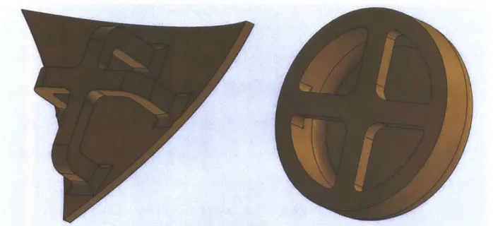
Figure 5: The robot's body armor (left) and cap (right) were designed with internal structures around which liquid rubber could
flow. After curing, the plastic part was fastened to the rubber without needing to pierce it with traditional fasteners. This method provided an effective way to fasten rigid parts to deformable rubber.
One of the most challenging limitations in designing with soft materials is the difficulty in fastening it to rigid structures. Although Smooth-On 00-50 is a very tough material, by definition, it does not result in a hard surface to which traditional rigid materials can be attached. Drilling holes in cured rubber can be effective, the process usually results in a jagged cut at the microscale, making the material more susceptible to tears in the area. An analogous rigid-body effect would be increased stress concentration at a corner resulting in brittle fracture. Naturally, the cured rubber withstands much more stress if undisturbed after curing as a solid piece.
Solid pieces were fastened to the rubber by allowing liquid rubber to solidify around support structures. To securely fasten the rigid body armor and cap to our soft rubber body, we designed a cross-like truss structure for the liquid rubber to surround, illustrated in Figure 5. Once cured, the rubber remained unpierced, increasing the stress it can withstand before tearing.
Two different variations of this technique are presented. The cap relies on structures internal to its surface while the body armor has a less concealed cross around which the rubber can cure.
2.3 Leak Detection Membrane Sensor
Leaks in the wall of a pipe create a sharp pressure drop in the surrounding fluid. The pressure around a leak decreases closer to the source, where water flows out.
Soft rubber membranes can be used to detect Figure 6: Material bounded by the rubber cord was removed to increase the membrane's sensitivity to external forces. Wires were threaded these leaks. When the membrane moves in the pipe around fastening holes to measure resistivity of
the cord, which is dependent in part on its length and arrives at a leak, the pressure drop results in a and therefore strain.
sucking force on the membrane. The membrane is drawn against the wall of the pipe, and this increases the friction on the membrane. This friction force changes the strain in the soft
membrane. By detecting the change in strain from the effects of the suction force, the increased friction force, the change in acceleration of the device transporting the membrane, or a
combination of all three, we can detect the presence of a leak.
We used a formula provided by You Wu et.al.3 to calculate the minimum length L [m] of our new membrane sensor for the 300mm diameter robot.
nV L =
-fs
3 You Wu, Kristina Kim, Michael Finn Henry and Kamal Youcef-Toumi, "Design of a Leak Sensor for Operating Water Pipe Systems", IROS 2017, under review.
In this equation, n represents the desired number of samples detected for each leak, V represents the velocity of the robot and sensor [m/s] (which is equal to the flow's velocity), andfs represents the measurement sampling frequency [Hz]. We wish to detect a minimum of n > 5 samples at a
conservative sampling rate off, = 100 Hz. We use a flow velocity of V = 0.6 m/s from our design constraints. With these parameters, we find that our membrane sensor must be a minimum 30mm in length.
We designed the membrane to be slightly longer than the minimum length. A slightly longer membrane increases the chances of successfully detecting a leak. The leak membrane was 81 mm in length, allowing use to collect at least 13 data points as it passes by a leak. The width of the membrane was 140 mm, with a thickness of 2.5 mm.
The membrane sensor integrates the resistive sensing element inside. A length of conductive rubber cord from Adafruit Industries was molded into the soft rubber membrane.
Solid-core copper wire was threaded through the endpoints of the conductive cable to measure its resistance. The length of the rubber cord slightly expands when the membrane is stretched by forces from the leak. This creates a measurable change in resistance and indicates a leak.
Slight modifications were made to the initial membrane design to increase sensitivity. Material inside the conductive rubber cord was removed in the shape of an arc to increase the sensitivity of the membrane, as shown in Figure 6. With part of the material surrounding the cord removed, forces applied to the membrane cause greater deformations in the cord, increasing its
2.4 Leak Sensor Mount
Figure 7: Membrane mount with adjustable clamp (left) and without (right). The adjustable clamp allowed us to test different thicknesses of membranes and vary the compressive force holding the membrane in place.
A small mounting device was created to hold the membrane leak sensor. The membrane mount was split into two parts, a base and a clamp, displayed in Figure 7.We chose a two piece device because it allowed us to test membranes with different thicknesses and determine their sensitivity. The clamp structure held 25mm of the membrane sensor within the membrane mount, leaving the remaining length exposed to the pipe. The membrane was sandwiched between the base and the clamp, and secured in place with four machine bolts. Brass threaded inserts were used to secure the clamp to the base. Each threaded insert was heat-set into the base of the membrane holder.
2.5 Sensor Arm and Position Encoder
An arm mechanism was designed to allow the membrane sensors to collapse while maintaining contact with the inner wall of the pipe.
Our robot must be robust in traveling through partially clogged and damaged pipes where the
diameter of the pipe may change. Each leak
detection sensors must be attached to the robot such that these changes in diameter do not reduce their
Figure 8: A hinge was designed to maintain constant effectiveness. The arm consists of three parts; the distance between the membrane and wall. Additionally, a wheel encoder was designed tothe inner pipe
measure the distance a robot travels. sensor arm, the wheel encoder, and the infrared
reflectance detector. The length of each arm was designed to be 125 mm long, such that it would create a nominal 30' angle with the sensor hub.
A hinge mechanism was designed to account for rotations of the arm. Illustrated in Figure
8 the hinge allows the membrane to remain in contact with the inner surface of the pipe,
regardless of the change in its diameter.
The robot must also track its location travelling through the pipe. An infrared reflectance
position encoder was integrated into the sensor arm. Figure 9: A wheel was integrated into the sensor arm and membrane mount with a position encoder to track the robot's location. The wheel is shown with an 0-A slot was designed into two of the robot's six arms ring (left) and without (right).
3M
against the inside wall of the pipe. A stepped radial groove was designed on the side of the wheel and filled with white paint. The white line is more reflective than the surrounding orange face. The change in reflectance when it passes by can be detected by the infrared reflectance sensor. Additionally, the wheel was designed with a groove such that an O-ring fit around it, increasing friction between the wheel and the pipe wall. The wheel is displayed in Figure 9.
Figure 10: A 30mm length of conductive
rubber cord was suspended between the arm and sensor hub to measure the arm's displacement
Sensors are used to measure the deformation of the arms and indirectly estimate the pipe diameter change. A second resistive cord was incorporated into the membrane arm to accomplish this, displayed in Figure 10. The cord connects the midpoint of the arm to the base of the hub. When the arm moves inward, forced by a reduction in pipe diameter, the cord will stretch and change in electrical resistance. The cord's change in resistance can be measured,
indicating the robot encountered a smaller pipe diameter or debris.
The arm sensor provides another method to distinguish debris and changes in pipe diameter from leaks. Our membrane sensors may deform if the robot encounters changes in pipe diameter, partially clogged areas, or other obstacles in the pipe. This deformation may be
mistakenly interpreted as a potential leak. However, we can distinguish false-positive detections from leaks by monitoring the position of the arm. Any obstacles or partial clogs would first come
15
contact the conical shaped arms before disrupting the membrane sensors. When both the arm and membrane sensor are disturbed, we can identify changes in diameter and debris from leaks.
2.6 Sensor Hub
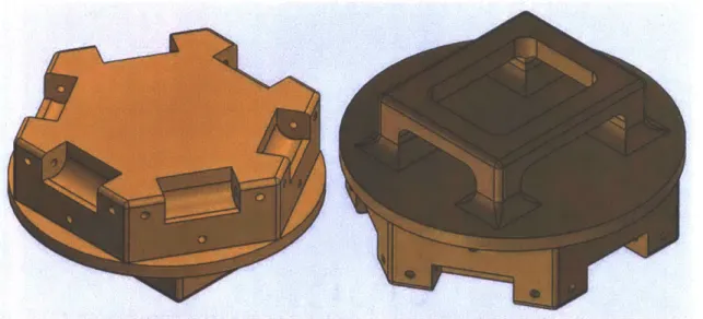
Figure 11: A sensor hub was designed to fasten the arms to the soft body of the robot. A rotation socket for each
sensor arm was designed on the rear side of the sensor hub (Left), and a truss was included of the forward facing side for mounting electronics (Right).
A sensor hub was designed to secure each of the arms and the central electronics for the
robot. Depicted in Figure 11, rotation sockets were included for each of the 6 membrane arms. Each arm was fastened with a 3mm diameter shaft, allowing it to rotate. A truss was also added on the forward facing side of the membrane to secure the robot's electronics. The dimensions of the truss were designed to be slightly larger than the electronics' footprint.
3. Electrical Design and Communication
The electrical requirements of our robot pose challenging constraints. The initial 50 mm diameter robot (2") contained a removable cap to charge its batteries and access the micro SD card.
However, this opening was very difficult to reliably seal. Risk of water damage and shorts increased each time the cap was opened and replaced. Our new 300mm diameter robot must be completed sealed. To do this, we must implement wireless charging systems, wireless
communication systems, and sealed sensors.
3.1 Microcontroller Framework - Intel Edison
The robot requires a computing unit for operation. The operational capabilities include leak detection, navigation, and data logging. We chose to use an Intel Edison Compute Module as a combined computing platform and microcontroller for the system. Other computing units were evaluated, such as the Feather Huzzah and the Particle Photon, but neither had the speed nor the number of analog pins that we needed to record data from each of our 14 sensors. Additionally the Intel Edison Compute Module contains built-in Wi-Fi, Bluetooth, and 12C capabilities. These will be beneficial in wireless communication for data transfer.
The Intel Edison's capabilities are difficult to access without expansion blocks. SparkFun's line of modular circuit blocks designed for the Intel Edison were used to take
advantage of its capabilities. Each block can be stacked in nearly any order as they communicate through 12C protocol.
3.2 Data Acquisition and Logging
Data acquisition necessitates a computing module. Each of the combined 14 sensors (six membrane sensors, six arm sensors, and to position encoders) output a voltage that varies approximately linearly with position. The analog voltage signal must be converted to a digital representation by the
computing module. We must use an analog-to-digital converter (ADC) to accomplish this.
Figure 12: An Intel Edison Compute Module was combined with modular breakout boards
from Sparkfun to facilitate data acquisition, data
storage via microSD card, and LiPo battery power source.
Four ADC blocks from SparkFun were added to measure analog signals. Each ADC allowed measurement of four individual channels, combining to a total of 16 possible inputs. We used 14 of the total channels. Two channels were used for each of the six arms (one membrane sensor and one arm sensor), and two additional channels were used for the position encoders.
SparkFun's 9 Degree-of-Freedom IMU block was added to track acceleration and orientation of the robot. The leak detection robot must navigate through pipe bends and
intersections, without falsely reporting them as leaks. When combined, the robot's arm sensors and membrane sensors distinguish debris and diameter changes from leaks, but they do not distinguish pipe bends from debris. The 9DOF IMU allows us to record the orientation and approximate position of the robot. By comparing the orientation of the robot with arm and
membrane sensor data, we can determine if the robot encountered debris, changes in pipe diameter, a pipe bend, or a leak.
SparkFun's MicroSD card block was used to record data from each of our sensors. The MicroSD unit increased the storage capacity of our device. Measurements from the four ADCs and the IMU were recorded by the MicroSD card block. A MicroSD card was permanently mounted in the block. The complete electronics stack can be seen in Figure 12.
3.3 Wireless Communication
Our robot must be communicate wirelessly for program uploads and data transfer. Wireless communication allows us to completely seal the robot, decreasing the changes of electrical failure from shorts. To achieve this, we took advantage of the Intel Edison's Wi-Fi capability. The Edison was configure to connect to a local Wi-Fi network on startup. We connect to the Edison over the local area network via SSH protocol. A static IP address can be defined for convenience after modification to the Edison's core Wi-Fi connection parameters.
Our robots must be able to receive new programs and transfer data wirelessly. While the Intel Edison was initially setup via hard wire serial communication with Intel's Edison Breakout Board, future updates and transfers must be conducted wirelessly. The Secure Copy Protocol (SCP) was used to transfer new files onto the Edison and transfer data from the Edison.
3.4 Power Requirements
The Intel Edison power requirements are greater than most other microcontrollers. The Edison's wireless communication flexibility comes at the cost of power consumption. Combined with Intel's breakout board (not used in final version of our electronics), the Edison requires an average of 0.32 W without Wi-Fi enabled and 0.41 W with Wi-Fi enabled4.
A SparkFun Battery Block designed to interface with the Intel Edison was used to supply power.
The block contains one 400mAh LiPo battery with an integrated charging circuit and micro-USB connector. The battery block is able to power the Intel Edison for approximately 1 hour.
3.5 Wireless Charging
Figure 13: Inductive coils from Adafruit Industries were used to wirelessly charge the robot. The transmitting coil (Top) induces a current in the receiving coil (Bottom) to energize the circuit.
4Intel Corp., "Power Consumption for the Intel® Edison Breakout Board," Intel, 20-Apr-2017. [Online]. Available: http://www.intel.com/content/www/us/en/support/boards-and-kits/intel-edison-boards/000006086.html. [Accessed: 22-May-2017].
Inductive coils were used to wirelessly charge the robot. A 5 V inductive charging transmitter and receiver set was purchased from Adafruit Industries, displayed in Figure 13. The transmitting coil circuit requires between 9 V and 12 V DC input. The receiving coil circuit produces a distance-dependent current at 5V DC. The maximum current output is 500mA when the coils are 2-3mm apart. The coils are approximately 40% efficient. The transmitting coil was connected to a DC power supply to provide the inductive circuit with current. The receiver module was placed approximately 5mm under the surface of the soft body of the robot to minimize the distance between the transmitting and receiving coil.
4. Fabrication and Assembly
4.1 Fabrication of Rigid Parts
Rigid parts inside the robot were fabricated through FDM 3D printing. These parts include the cap, sensor hub, sensor arms, position encoder wheel, and membrane mount. A Stratasys Fortus 250mc was used to print the parts. Each of these parts were load bearing structures and they were printed with a high density fill.
4.2 Fabrication of Membrane Sensors
Figure 14: Two membrane molds were created to fabricate leak detection membranes. The first iteration (left) was used to create membranes of varying sizes by restricting the flow of liquid rubber with a bead of hot glue. Once an optimal length was measured, a second mold (right) was created to match these dimensions.
Each membrane sensor was cast with a 3D printed mold. The larger mold displayed in Figure 14 was 3D printed with inside dimensions 150 mm by 140 mm by 4 mm deep. The mold was designed to be longer than the length of the membrane so that membranes of varying length could be cast and tested. The length of the mold was changed by partitioning it with a bead of hot glue. The mold was marked at a distance of 25mm from to bottom to indicate the point up to which the membrane would be held by the membrane mount.
A length of conductive rubber cord was cut such that the peak of its arc did not pass this
line. Each end of the conductive cord was placed in the groove that most closely matched the distance between two machine bolt fasteners on our membrane mounts. Mold Star 30 was poured into the mold and the conductive cord was periodically pressed down into the material to prevent it from rising to the top. It was held near the bottom of the mold by the material after
approximately 20 minutes, once the liquid rubber had cured to a higher viscosity.
Our initial membranes were too thick and a second mold was printed with a depth of 2.25mm. Each of the membranes must not exceed 2.5 mm in thickness to fit in to membrane mount. Additionally, we hypothesize that thicker membranes are not as sensitive to deformations from small forces. The new dimensions of this mold were matched to our results from testing the maximum membrane length that could support its own weight.
4.3 Assembly of Membrane Mounts
Each membrane was removed from the mold after curing for a minimum of three hours. The membrane was trimmed to remove any extraneous overflow and notches. Additionally, a slight fillet was added to some edges by carefully trimming the sharp corner with scissors. Each membrane was matched with a membrane mount, and the mount's holes were lined up with the end of the membrane's conductive cord. A concentric hole was marked and pierced on the membrane. Thin wire used in motor windings was threaded twice through the membrane on
either side of the hole. Threaded brass inserts were heat-set into the membrane mount and the
membrane was fastened between the mount and the clamp with four <M2> machine bolts. The wires threaded through the membrane were positioned such that they exited the membrane mount toward the inner surface. This protects the wires against scraping and potential debris in the pipe.
4.4 Fabrication of Molds and Design Changes
The initial 50 mm diameter robot was cast with a 3D printed mold. Indents were created to hold the smaller cap and electronics hub. Our initial 300
mm robot design was created with the expectation that a 3-axis CNC machine could fabricate two halves of a mold in the same way.
A CAD model 300 mm robot mold was created with
inset locations to hold the cap, body and armor pieces, displayed in Figure 15. Each half of the mold would be held with clamps while liquid Smooth-On 00-50 cured to form the soft rubber body. However, it was determined that the mold was impossible to fabricate without the use of a 5-axis CNC milling station. The vertical height change of the
robot's cross sectional area was too deep and the chuck of a typical 3-axis CNC machine would collide with the wall while trying to carve areas near the edge of the mold.
j
Figure 15: The initial mold to cast a 300mm diameter robot. Due to manufacturing constraints requiring 5-axis CNC tools, this mold was not practical to fabricate.
Figure 16: The initial mold was cut into shells to
save material when 3D printing. Shells were layered to minimize build volume.
Our mold was re-designed into shells and divided into pieces to be 3D printed. Our limiting constraint was the 254mm by 254mm by 305mm (lOin by 1 Oin by 12in) print volume of a Stratasys Fortus 250mc. The shells were carefully sliced, layered, and arranged such that the entire mold could be completed in one print, as shown in Figure 16. However, we found
the total build time to be approximately 152 hours (Just Figure 15: Hexagonal "Low Polygon" version of the initial mold significantly reduces fabrication complexity. over 6 days) with a high density fill. This was reduced to This mold can be used to cast the upper portion of the
robot.
126 hours (just over 5 days) with a low density fill. After
slight modifications that decreased design complexity (such as changing the gradual curve of the body to flat surfaces) we achieved a build time of 103 hours (just over 4 days) and quickly determined that 3D printing the mold would not be practical due to time and cost.
The mold design was reduced to hexagonal pyramids so it could be produced with inexpensive flat sheets. A "low polygon" version of the mold could be
constructed from flat panels of foam core. This version were added to provide support.Figure 16: Fabrica ted upper region soft body mold. Ribs of the mold was divided into two halves, an upper half (with respect to the robot orientation) that shapes the neck and main soft body, and a lower half to shape the arm support, shown in Figure 18. Each half of the mold was further divided into sections. Finally, each section was designed so that it could be created from six identical panels.
Each panel of the mold was cut from 5mm thick foam board. The panels were assembled with duct tape to form a complete section. Vertical ribs were also added to the upper half to prevent joints from failing due to the weight of the rubber, displayed in Figure 16.
Figure 18: A comparison between the robot's soft-body that would have been produced with the initial mold design, and the body produced using a hexagonal "Low Poly" mold.
A if ?L 11
67I
Figure 17: The robot was molded is two sections before being joined together. The upper half (left) and the lower half (right) were filled with
Smooth-On 00-50 to form the soft body of the robot. The sensor assembly was placed into the lower section mold before the body was cast, and wires were taped at the bottom of the mold for accessibility after the rubber had cured.
A comparison between the upper half of the soft body that would have been produced by the
initial mold design and one produced with the "Low Poly" design can be seen in Figure 18. Both fabricated molds, the upper half and the lower half, are displayed in Figure 17.
4.5 Assembly of Sensor Arm and Position Encoder Each sensor arm, membrane mount, and position encoder was fastened with an axle to the sensor hub. A 35mm outer
diameter O-ring (27mm inner diameter, 4mm thick) was snugly fit around the wheel for the position encoder before assembling it to the arm. Both arms with a wheel encoder were also assembled after each wheel was positioned between the membrane holder's hinge supports, as seen in Figure 19.
All parts needed additional post fabrication processing. All
parts were soaked in a warm water bath to remove support
material. Additionally, axle holes in the sensor arm and membrane
mount was reamed with a 3/16" hex key to slightly increase its 19: Eachmo bure s assemble itn encoder, sensor hub.
diameter.
j
4.6 Molding the Soft Body
The completed hub assembly pictured in Figure 20 was integrated into the soft body of the robot. Wires from each arm were grouped together, pulled through the mold, and taped to the outside wall. A piece of tape was placed over the wires where they bent around the mold and a flat plate was glued to the bottom of the mold.
Figure 20: The hub assembly was placed in the lower half of the
mold before Smooth-On 00-50 was used to cast the soft body.
Each membrane mount was glued to the inside wall of the mold to prevent it from
shifting while rubber was being cured. Hot glue was used to cover the position encoder wheel on the arms, such that it could be removed after casting to free the wheel. Smooth-On 00-50 was poured into the mold to cast the lower and upper sections of the robot, displayed in Figure 17.
Figure 21: (Left) A cylindrical can was place in the mold to create a circular void in the rear section of the robot.
(Right) The void allowed the diameter of the robot to compress and expand when encountering changing pipe diameters.
A cylindrical can was used to create a void in the back of the lower section, illustrated in Figure
21. This circular void allows the robot to compress with changes in pipe diameter. The molded
robot when compressed is also depicted in Figure 21.
The robot's cap was secured on the bottom of the upper half mold, displayed in Figure 16, and the mold was filled halfway with Smooth-On 00-30. After both halves of the mold were
cast, electronics were assembled into the sensor hub truss and the two halves were joined. The lower half of the soft body was placed on top of the upper half, and Smooth-On 00-30 was used to fasten the two halves together.
5. Experimental Testing
5.1 Verification of Membrane Sensors
The resistance of each membrane and arm sensor was measured at rest and under load. A nominal resistance was measured as a base line against which the resistance in deformed states can be compared. The arms were expanded and compressed to determine a change in resistance from the nominal value. We can more accurately distinguish leaks from debris and pipe diameter changes by understanding each sensor's response to load. The results of our testing are presented below. Membrane A All Units in kW 12 15-16 22 15-16 13 10 13 30-31 13.14 10 --- ---- --- -- ----Nominal Resistance: 11-12 k
Bending Out: 8 kfO
Bending in: 12.5 kQ Membrane B All Units in kW 8.9 10.0 90 7.8 7.5 8.3 13 10.6 7.8 7.5 * 0 0 a 0 7.2 10 16.5 7.8 7.5 --- --- -Nominal Resistance: 6.7 kO Bending Out 5.7 kO Bending In: 7.8 ka
Figure 22: Resistance measurements from Membrane A (Top) and Membrane B
(Bottom).
Each membrane was designed to have a sharp change in resistance. Dots presented in the figures show points at which the membrane was pulled in the labeled direction.
Membranes that
demonstrate a significant change from the nominal value are the most
sensitive to detecting pipe leaks. However, each membrane is exhibits
different behavior.
The machine bolts that fasten the clamp to the membrane holder were not uniformly tightened after assembling the membranes in each holder. We can visually estimate the tightness
of each bolt by the depth it rests in each threaded insert. We also hypothesize that this tightness affects the sensitivity of the membrane to deformations. When the bolts are tightened, the membrane will be held more rigidly inside the membrane mount so that any deformations of the membrane will be prevented by friction force between the mount and the membrane. The bolt
fastening the left side of Membrane A appears to be tighter than the bolt on its right side. Similarly, the bolt on Membrane B's left side appears significantly tighter than its right. Our hypothesis can be evaluated by analyzing the change in resistance of each membrane to the same
deformation.
Membrane A in Figure 22 is a very sensitive. The baseline resistance is approximately 11 kE2. It exhibits a change of at least 2-3 kK when deformed in most locations. The deformation is imposed by pulling the membrane in the longitudinal direction. Its left side appears to be less sensitive than its right, only experiencing a 1-2 kQ resistance change when deformed on that side. Similarly, the right side of Membrane B in the same figure is not as sensitive as the left side. The baseline resistance of Membrane B is 6.7 kQ due to variations in the molding process. While the left side of Membrane B experience a resistance change of 2 kQ from the nominal value, the right side of Membrane B experiences less than a 1 kQ change. These experimental results confirm our hypothesis, linking the tightness of machine bolts holding the each membrane
to its sensitivity.
This relationship implies that we can tune a membrane by changing the torque of the machine bolts holding it in place. We must tune the membrane by adjusting the clamping force to achieve greater sensitivity.
Membrane C All Units in kQ 14 13 20 11.7 9.9 12 13 20-21 11.0 9.9 11.0 12.8 22-24 11.2 9.4 --- ---0 Membrane D All Units in ka 10.0 11 11.6 8.3 7.5 8.9 10.5 14.7 8.3 6.6 . 0 0 0 6 7.8 10.0 17 8.1 6.6 *- - - - - - - - - - - - - - - - - - - - - - - -
-Nominal Resistance: 8.8 kO Nominal Resistance: 6.9 k
Bending Out: 6.4 kC BendingOut: 5.0 k
Bending in: 11.0 ka Bonding in: 8.6 k0
Figure 23: Resistance measurements from Membrane C (Top) and Membrane D (Bottom).
Membrane E All Units in k 10.6 12.5 15 11.4 10.1 10.4 13 19-20 11.4 9.6 9.9 12.6 24-25 10.5 9.6 --- ---0 Membrane F All Units in k 8.3 8.6 8.0 8.2 7.7 a 0 * a a 8.7 9.0 11.8 8.6 7.2 7 0 a a a 7.6 8.6 18.5 8.2 7.2 --- --- a ---a
-Nominal Resistance: 9.31 k Nominal Resistance: 6.4 k
Bending Out: 6.6 k Bending Out: 5.8 kO
Bending In: 11.5 k Bendingin: 7.7 kO
Figure 24: Resistance measurements from Membrane E (Top) and Membrane F (Bottom).
The difference in nominal resistance of the membranes may be explained by how they were fabricated. Each membrane was individually molded. Mold Star 30 was mixed in separate batches for each membrane before it was cast in the mold. While the concentration of
0 0
40 .3
components in each batch was kept as consistent as possible, each membrane may have slight variations in composition, affecting the nominal resistance.
5.2 Verification of Arm Sensors
Sonsor Arm Stns Am
Sensor Arm Nominal Resistance Bend Inward
A 16 13 B 60 44-45 C 16 13 D 22-23 16 E 18 21 F 14 12 All Measurements In kf
Figure 25: Resistance measurements of each sensor arm while at rest
(nominal) and under load. The resistance unexpectedly decreased underload in most tests.
Additionally, the resistance of each sensor arm was measured nominally and under load. The results are presented in Figure 25. Although we expected the resistance to increase under load, most of the sensors experienced a decrease in resistance when pressed inward, toward the center of the sensor hub. This may be explained by the surrounding rubber. Even though the cord may have stretched in length (increasing the resistance), the surrounding rubber may have also increased its cross-sectional area (decreasing the resistance). This compound effect may have
cause a net decrease in resistance when the sensor arm is pressed inward.
One arm sensor in particular demonstrated far greater resistance that the others. While the exact cause is unknown, the increased resistance may be due to permanent deformation of the sensor cord.
5. Conclusions and Recommendations
We successfully designed and fabricated a 300mm pipe leak detection robot. Many design choices were re-evaluated and modified to scale the initial 50mm diameter device. We incorporated wireless communication methods and a wireless charging system in the robot, allowing us to seal it's electronics from the environment. Additionally, we incorporated a position encoder to more accurately measure the robot's position in the pipe. While we did not conduct a field test of the robot, we verified its sensors and functionality.
We found many tests departed from our expected results, such as the arm sensor's response to load. While arm sensors on the 50mm diameter robot increased in resistance under load, we found that arms sensors on the 300mm diameter robot decreased in resistance. We attribute this to a compound effect of the soft material's deformation.
We recommend that a field test is conducted to illuminate behavior that is not possible to discover in controlled environments. We also wish to test the position encoder in conjunction with the IMU to determine their combined accuracy. Finally, we wish to empirically test the minimum pipe diameter through which the robot can successfully pass.