Design of Multi-Degree-of-Freedom Tuned-Mass
Dampers using Perturbation Techniques
by
Justin Matthew Verdirame
Bachelor of Science, Mechanical Engineering
Massachusetts Institute of Technology, 2000
Submitted to the Department of Mechanical Engineering
in partial fulfillment of the requirements for the degree of
Master of Science in Mechanical Engineering
at the
MASSACHUSETTS INSTITUTE OF TECHNOLOGY
June 2003
©
Massachusetts Institute of Technology 2003. All rights reserved.
A uthor ...
...
Department of Mechanical Engineering
June 5, 2003
Certified by ...
Samir A. Nayfeh
Assistant Professor
-Thesis Supervisor
Accepted by
Chairman, Department Committee o
Ain A. Sonin
n Graduate Students
MASSACHUSEUT NSTITUTE OF TECHNOLOGY
BARKER
JUL 0 8 2003
Design of Multi-Degree-of- Freedom Tuned-Mass Dampers
using Perturbation Techniques
by
Justin Matthew Verdirame
Submitted to the Department of Mechanical Engineering on June 5, 2003, in partial fulfillment of the
requirements for the degree of
Master of Science in Mechanical Engineering
Abstract
In precision assemblies, components must be aligned relative to another with high ac-curacy. The components are typically supported on flexures, which exhibit negligible
damping; therefore, vibration of the components becomes an issue. In this thesis
(and
in concert with Zuo and Nayfeh [50]), we develop the concept of the multi-degree-of-freedom (MDOF) tuned-mass damper (TMD) to damp multiple modes of vibration of a primary structure. A MDOF TMD consists of a rigid mass connected to a pri-mary mass with damping and stiffness tuned to suppress vibration in as many as six modes of vibration of the primary structure. Zuo and Nayfeh [50] have shown that, given size and location of the absorber mass, numerical optimization can efficiently determine the values of the springs and dampers but not their locations.
The goal of this thesis is to develop analytical approximations for the design and 'attainable performance of MDOF TMDs. The use of perturbation methods allows the locations of the springs and dampers to be optimized, in addition to their values. First, we examine the single-degree-of-freedom tuned-mass damper and use eigen-value perturbation, with the mass ratio as the small parameter, to determine the approximate eigenvalues and eigenvectors. To demonstrate the application of the ap-proximate eigenvalues and eigenvectors for design, we show that perturbation results for the minimax design, which maximizes the minimum damping coefficient, are a Maclaurin series expansion of the exact solution. Then, we extend the method to multiple degrees of freedom. Approximate eigenvalues and eigenvectors are deter-mined for the coupled system. We use the minimax criterion to illustrate the design procedure using the expansion. The method is applied to a two-DOF system and a three-DOF system, and for the two-DOF system the results are compared with those of a numerical optimization procedure.
Thesis Supervisor: Samir A. Nayfeh Title: Assistant Professor
Acknowledgments
This thesis has taken me so long to complete and so many people have helped me that I hope I do not forget anyone.
First, I must thank my advisor, Prof. Samir Nayfeh, for his instruction, insight, and unwaivering support. His excellence in all areas, from theory to practice, never ceases to amaze me. His ability to teach such varied and complicated topics have made him a great teacher. Furthermore, his creativity, enthusiasm, motivation, and kindness have made him an even better mentor. Finally, he must be commended for never getting frustrated by my inability to do algebra or write Matlab scripts.
Next, I must thank my labmates for providing encouragement, advice, and in-struction. The "weavies," Jonathan Rohrs, Mauricio Diaz, and Emily Warmann have suffered tremendously by sharing office space with me for the past two years. Jonathan is faithfully answers my questions on everything ranging from software to math to design to current events. prepared to answer my questions (99% of which are stupid) and provide a discussion of current events. Mauricio answered many of my machine design and math questions and introduced me to Tacos Lupita. Lei Zuo has provided valuable insight on a number of fronts, but most importantly in my work on MDOF TMDs. Kripa Varanasi provided instruction in a variety of tasks and tech-niques. Dhanushkodi Mariappan always tried to make me stronger by helping him lift heavy machinery around the lab. Andrew Wilson provided excitement and kept me awake by yelling "Dood!" Maggie Beucler, Prof Nayfeh's administrative assistant, has been kind and encouraging throughout.
Countless others have made the last three years a lot fun. I am indebted to my fellow 2.003 TAs, Vijay Shilpiekandula, Xiaodong Lu, and Yi Xie, because their hard work and enthusiasm made the experience fun and educational (special thanks to Yi for her instruction in the "art" of using chopsticks). Joe Cattell and I started our own "company," and Joe taught me controls for the quals. Jeff Dahmus always had time for a conversation whenever I felt like procrastinating. Every game was exciting with the Neanderthals hockey team. Max Berniker is a fearless leader, as well as a
good roommate. I would like to thank all of my friends for their camaraderie and support.
I would also like to thank everyone else, too many to name here, who aided me in this research.
Most of all, I would like to thank my family especially my parents, Joe and Nancy. Their support and encouragement in all of my endeavors is relentless and greatly appreciated. My brother, Mike, and sister, Claudia, have provided constant "encouragement" with their incessant MIT jokes and fighting beaver impersonations. Nick and White Sox have provided me with an endless supply of white hairs to bring back from each visit home.
Contents
1 Introduction 19
1.1 M otivation . . . . 19
1.2 Term inology . . . . 21
1.3 Previous Literature . . . . 21
1.3.1 Concept of the Multi-Degree-of-Freedom Tuned-Mass Damper 26 1.4 O verview . . . . 26
1.4.1 Single-Degree-of-Freedom Tuned-Mass Damper . . . . 27
1.4.2 Multi-Degree-of-Freedom Tuned-Mass Damper . . . . 27
1.5 Summary of Contributions . . . . 28
2 Single-Degree-of-Freedom Tuned-Mass Damper 29 2.1 Scaling . . . . 29
2.1.1 Undamped SDOF TMD . . . . 30
2.1.2 Damped SDOF TMD . . . . 31
2.1.3 Scaling of Higher Order Terms . . . . 32
2.2 Perturbation Expansion . . . . 33
2.3 Approximate Minimax Design . . . . 41
2.3.1 Comparison to the Exact Minimax Design . . . . 42
3 Multi-Degree-of-Freedom Tuned-Mass Damper 45 3.1 Equations of Motion and Scaling . . . . 45
3.1.1 Scaling . . . . 47
3.3
3.4
3.2.1 The Expansion to O(1) . .
3.2.2 The Expansion to O(e1/2) 3.2.3 The Expansion to O(6) . .
3.2.4 The Expansion to O(3/2)
3.2.5 Outer Expansion . . . . .
3.2.6 Intermediate Expansion
3.2.7 Inner Expansion . . . . Approximate Minimax Design . . Design Examples . . . .
3.4.1 Two-DOF System...
3.4.2 Three-DOF System . . . .
4 Conclusions and Future Work
4.1 Findings . . . .
4.2 Future W ork . . . .
4.2.1 Two Parameter Expansion . . . .
4.2.2 Tuning Multiple Modes of the Absorber
Primary Structure . . . .
4.2.3 Other Work . . . .
A Single-Degree-of-Freedom Tuned-Mass Damper Forcing
A.1 Method of Multiple Scales . . . . A.1.1 Expansion to O(1) . . . . A.1.2 Expansion to O(6) . . . . A.1.3 Expansion to O(E2) . . . .
A.1.4 Expansion to O(c3) . . . .
A.2 Approximate H,, Optimal Design . . . .
to One Mode of the 49 50 50 52 53 55 57 58 60 60 65 73 73 74 74 76 77 Subject to Harmonic 79 79 81 81 83 84 85
B Single-Degree-of-Freedom Tuned-Mass Damper Subject to Random
B.1 Method of Multiple Scales . . . .
B.1.1 Expansion to O(1) . . . .
B.1.2 Expansion to 0(c) . . . .
B.1.3 Expansion to 0(62) . . . .
B.2 Approximate H2 Optimal Design . . . . B.2.1 Comparison to the Exact H2 Optimal Design
C Derivation of the Coupled Equations of Motion
D Assignment of the Absorber Mode Shapes
E A Note on Solvability Conditions
. . . . 93 93 94 101 . . . . 102 . . . . 103 105 109 113
List of Figures
1-1 An aluminum block supported on flexures serves as a mock-up of an
optical assembly typical of a lithography system. Aluminum has
ap-proximately the same density as glass. . . . . 20
1-2 Vibration mode shapes of the mock-up shown in Figure 1-2. . . . . . 20
1-3 Diagram of a vibratory system comprising a mass M to which a
single-degree-of-freedom tuned-mass damper m is attached. . . . . 22
1-4 Frequency responses for various tuned-mass damper tuning methods: undamped (dots), solid (Den Hartog, approximate H,,), minimax (dashed),
H 2 (dash-dot) . . . . 22
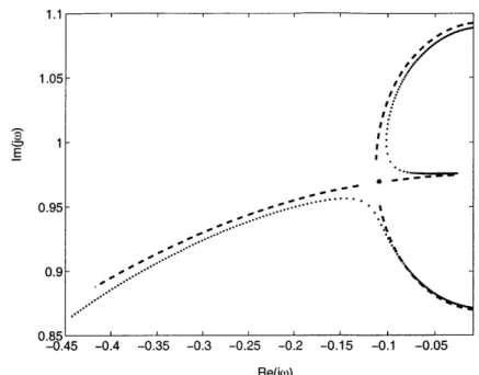
1-5 Eigenvalue locations for the minimax tuned SDOF TMD as the
damp-ing is varied. Only the upper half-plane pole locations are shown be-cause the eigenvalues form complex conjugate pairs. The poles coalesce
for the minimax damping value. . . . . 23
1-6 Diagram of a vibratory system comprising a mass M to which a
tuned-mass damper m is attached. . . . . 25
1-7 Diagram of a two-DOF system with (a) two SDOF TMDs and (b) one
two-DOF TM D . . . . 27
2-1 Diagram of a vibratory system comprising a mass M to which a
single-degree-of-freedom tuned-mass damper m is attached. . . . . 30
2-3 Comparison of the actual eigenvalues (dots) and O(c) approximations
to the eigenvalues (dashed) for a perfectly tuned (ki = 0) SDOF TMD
with a mass ratio of 5% (c = 0.22) as the damping (co) is varied. . . . 37
2-4 Outer expansion: Comparison of actual eigenvalues (dots) and O(E2) approximations to the eigenvalues (solid) for a SDOF TMD with a
mass ratio of 5% with ki = -1, k2 = 0, and ci = 0 as the damping
(co) is varied. . . . . 39
2-5 Comparison of actual and approximate eigenvalues including W3 for
a perfectly tuned (ki = 0) SDOF TMD with a mass ratio of 5% as
the damping (co) is varied: outer expansion (dashed), intermediate
expansion (dashdot), exact (dots). . . . . 40
2-6 Comparison of actual and approximate eigenvalues including w4 for
a SDOF TMD with a mass ratio of 5%, k, = 0, c1 = 0, and k2 =
0 as the damping (co) is varied: outer expansion (x), intermediate
expansion (solid), exact (dots). . . . . 41
2-7 Outer expansion when the eigenvalues are close to coalescence (ko = 1,
ki = 0, k2= -2, c1 = 0) as the damping (co) is varied: 0(62)
approxi-mate eigenvalue locations (dashed), exact eigenvalue locations (dots). 42
3-1 Diagram of a vibratory system comprising a mass M to which a
tuned-mass damper m is attached. . . . . 46
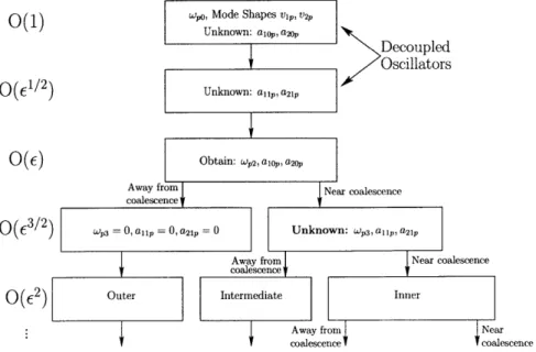
3-2 Diagram indicating the various steps in the perturbation expansion. . 48
3-3 Comparison of the actual eigenvalues (dots) and O(E) approximations
to the eigenvalues (dashed) for a perfectly tuned (k1 = 0) SDOF TMD
with a mass ratio of 5% (c = 0.22) as the damping (co) is varied. . . . 52
3-4 Outer expansion: Comparison of actual eigenvalues (dots) and 0(E2)
approximations to the eigenvalues (solid) for a SDOF TMD with a
mass ratio of 5% with k, = -1, k2 = 0, and ci = 0 as the damping
3-5 Comparison of actual and approximate eigenvalues including Wp3 for
a perfectly tuned (k, = 0) SDOF TMD with a mass ratio of 5% as
the damping (co) is varied: outer expansion (dashed), intermediate
expansion (dashdot), exact (dots). . . . . 55
3-6 Comparison of actual and approximate eigenvalues including wup4 for a
SDOF TMD with a mass ratio of 5%, k, = 0, ci = 0, and k2 = 0 as the damping (co) is varied: outer expansion (x), intermediate expansion
(solid), exact (dots). . . . . 56
3-7 Outer expansion for a SDOF TMD when the eigenvalues are close
to coalescence (ko = 1, ki = 0, k2 = -2, ci = 0) as the damping
(co) is varied: O(2) approximate eigenvalue location (dashed), exact
eigenvalue locations (dots). . . . . 57
3-8 Diagram of the two-DOF system with tuned-mass damper: 11 = 1,
M = 1, I = 0.0833, K1 = 3, K2 = 5, r1 = 0.333, m = 0.05M,
Id= 0.00561, 13 = 0.333. . . . . 60
3-9 Frequency Responses: (a) shows the displacement x1 of the center of
main mass. (b) shows the rotation 61 of the center of main mass. Original system without TMD (dots), 0(c) perturbation design (thin
solid), O(c2) perturbation design (thick solid), numerically optimal
de-sign with fixed l2 (dashdot), and numerically optimal design with
op-tim ized 12 (dashed). . . . . 63
3-10 Eigenvalue Locations for Mode 1 of the two-DOF example: O(E)
ap-proximation as the damping is varied (0), 0(E2) approximate as the
damping is varied (x), O(e) perturbation design (0), O(E2)
pertur-bation design (*), numerically optimal design with fixed 12 (*), and
3-11 Eigenvalue Locations for Mode 2 of the two-DOF example: O(E)
ap-proximation as the damping is varied (o), O(E2) approximate as the
damning is varied (x), O(E) perturbation design (0), O(E2)
pertur-bation design
(*),
numerically optimal design with fixed 12(*),
andnumerically optimal design with optimized 12 (I). . .. . .. . . . 64
3-12 Diagram of a three-DOF system with a tuned-mass damper. M = 1,
K1 = 1, K2 = 1, K3 = 2, I = 0.0853, m = 0.05M, Ia = 0.001157,
rX = 0.1667, ry = 0.0833, bX = 0.5. by = 0.1667 . . . . 66 3-13 Frequency response showing the response of M in the x-direction due
to ground displacement in the x-direction. Original system without
TMD (dots), O(E) perturbation design (dashed), O(E2) perturbation
design (solid). . . . . 67
3-14 Comparison of actual and approximate eigenvalues for mode 1 of the three-DOF example as the damping is varied: O(E) approximation
(cir-cles), O(E2) approximation (x), exact (dots), O(E) design (diamond),
0 (E2) design (*). . . . . 67
3-15 Comparison of actual and approximate eigenvalues for mode 2 of the
three-DOF example as the damping is varied: O(E) approximation
(cir-cles), 0(e2) approximation (x), exact (dots), O(E) design (diamond),
0 (E2) design (*). . . . . 68
3-16 Comparison of actual and approximate eigenvalues for mode 3 of the
three-DOF example as the damping is varied: O(E) approximation
(cir-cles), 0(E2) approximation (x), exact (dots), O(E) design (diamond),
0 (E2) design (*). . . . . 68
3-17 Comparison of actual and approximate eigenvalues for mode 1 of the
three-DOF example as the damping is varied for I = 0.04921: O(E)
approximation (circles), O(E2) approximation (x), exact (dots), O(E)
3-18 Comparison of actual and approximate eigenvalues for mode 2 of the
three-DOF example as the damping is varied for Id = 0.04921: 0(E)
approximation (circles), 0(2) approximation (x), exact (dots), 0(c)
design (diamond), O(2) design (*). . . . . 71
3-19 Comparison of actual and approximate eigenvalues for mode 3 of the
three-DOF example as the damping is varied for Id = 0.04921: O(E)
approximation (circles), O(E2) approximation (x), exact (dots), O(E)
design (diamond), O(E2) design (*). . . . . 72
A-1 Frequency response of aop for various damping co with k, = 0: original
system without TMD (dots), co = 0 (dashed), 0(c) design (bold solid),
various non-optimal designs (solid). . . . . 87
A-2 Frequency response of aop
+
a1 for various tuning k2 with ci = 0:O(62) design k2 = -2 (bold solid), various non-optimal designs (solid). 88
A-3 Frequency response with mass ratio of 0.05: original system without
TMD (dots), O(c) design (dashed), 0(c2) design (solid), optimal
de-sign (dashdot). . . . . 89
B-1 Spectrum of excitation force: (a) Spectrum of -, (b) Spectrum of w. . 93
B-2 Integration contour . . . . 96
B-3 Mapping of z-plane (a) to w-plane (b) for w = c-(z) given by (B.22) 97
B-4 Mapping of z-plane (a) to w-plane (b) for w = -(z) given by (B.23) 97
B-5 Grid of points in the upper half of the z-plane. . . . . 98
B-6 Mapping of the z-plane grid shown in Figure B-5 under the mapping
w = -(z) as given by (B.22). . . . . 98 B-7 Schematic of pole locations for H(c-). . . . . 99
B-8 Contour plot of the variance E[A2] as a function k, and co. . . . 100
C-1 Diagram of a vibratory system comprising a mass M to which a
tuned-mass damper m is attached. . . . 106
List of Tables
3.1 Results of the perturbation-based design: The perturbation method to
0(c) returns a distance between the springs of 12 = 0.1088, which is
used as a fixed parameter for the O(2) design. . . . . 61
3.2 Optimization results from Verdirame et al
[39].
The perturbationmethod to O(e) returns a distance between the springs of 12 = 0.1088,
which is used as a fixed parameter in the optimization algorithm. In a second numerical optimization, the distance between the springs is
taken as an additional design variable to be optimized. . . . . 62
3.3 Various optimal designs: The perturbation method to 0(e) returns
a distance between the springs of 12 = 0.1088, which is used as a
fixed parameter in the optimization algorithm. In a second numerical optimization, the distance between the springs is taken as an additional
design variable to be optimized. . . . . 62
3.4 Results of the perturbation-based design: The perturbation method to
O(E) returns the spring and damper locations and the angle
#,
whichis used as a fixed parameter for the O(62) design. . . . . 65
3.5 Three-DOF absorber parameters determined by the perturbation
meth-ods. ... ... 66
3.6 Results of the perturbation-based design for Ia/I = 0.492: The
pertur-bation method to O(e) returns the spring and damper locations and
Chapter 1
Introduction
1.1
Motivation
In the design of precision machines and precision assemblies, components must be positioned to within tight tolerances. Furthermore, the support structures must not deform these components by applying unnecessary stresses. Therefore, the compo-nents must be kinematically constrained. In other words, the structure must be statically determinate. To accomplish this task, components are often supported on flexures, elastic elements which are relatively stiff in usually one direction and com-pliant in the other directions. Because these flexures are elastic and typically have negligible damping, vibration of the components relative to the support structure be-comes a problem. Therefore, a method of introducing damping into the system must be found.
An example of such a system is the optical assembly of a lithography system. A mock-up of a beam splitter supported on flexures is shown in Figure 1-1. Its vibration mode shapes are shown in Figure 1-2. To maximize performance of the lithography system, the vibration of the optical elements should be well damped.
A number of methods exist for adding damping, but precision systems have special
requirements that impose limitations. Typical methods such as adding viscoelastic materials are unacceptable in precision applications because creep is introduced into the system. Electromagnetic dampers are often difficult to use when retrofitting a
Figure 1-1: An aluminum block supported on flexures serves as a mock-up of an optical assembly typical of a lithography system. Aluminum has approximately the same density as glass.
Mode # 1 N --Mode # 2 Mode # 3 N y x Mode # 4 N y x Y x Mode # 5 N -y x Mode # 6 Y X
system. Fluid dampers are unacceptable in systems where cleanliness is a concern. An inertial, or tuned-mass, damper is a good alternative because it is easy to retrofit; and it does not introduce creep.
1.2
Terminology
A tuned-mass damper
(TMD),
or dynamic vibration absorber (DVA), consists of a rigid mass connected to a primary mass with damping and stiffness tuned to suppressvibration of the primary mass (see Figure 1-3). There are three common tuning
methods (see Figure 1-4). The H, optimal tuning minimizes the maximum response to harmonic excitation, which for the single-degree-of-freedom (SDOF) TMD, sets the two peaks in the frequency response to be of equal and minimum height (see Figure 1-4). The H2 optimal design minimizes the energy in the system, or equivalently, minimizes the variance to white-noise (random) excitation. The third common tuning method is obtained from "minimax" optimization of the damping; the minimum
damping coefficient is maximized. This design differs from the H. and H2 tunings
because it is not input-output based. When the input, or disturbance(s), are not well known, the minimax design is often preferable to the H, and H2 optimal designs. This design maximizes the stability margin and robustness of the system. A result of this design for the SDOF TMD is that the system has one repeated eigenvalue instead of two distinct eigenvalues (see Figure 1-5). Therefore, the frequency response has a single peak (see Figure 1-4). This thesis focuses primarily on the minimax design.
1.3
Previous Literature
The concept of the tuned-mass damper was created by Frahm [9], who received a patent for the idea in 1909. The first analysis of the TMD was performed by Den Hartog and Ormondroyd in 1929 [26]. Their idea for the optimal tuned-mass damper was based on the idea of "equal peaks." They derived a simple tuning which very
m X2
k c
M _ X
K
Figure 1-3: Diagram of a vibratory system comprising a mass M to which a single-degree-of-freedom tuned-mass damper m is attached.
0.5 0.6 0.7 0.8 0.9 1 1.1 Frequency [rad/sec]
1.2 1.3 1.4 1.5
Figure 1-4: Frequency responses for various tuned-mass damper tuning methods:
un-damped (dots), solid (Den Hartog, approximate H..), minimax (dashed), H2
(dash-dot) 10 8 CM 0O6 4 2 VO
-1.1 1.05-0.95. 0.9-0.85 -0.2 0 Re(jo)
Figure 1-5: Eigenvalue locations for the minimax tuned SDOF TMD as the damping is varied. Only the upper half-plane pole locations are shown because the eigenvalues form complex conjugate pairs. The poles coalesce for the minimax damping value.
nearly approximates the H, optimal tuning and is given by 1
f
= I(1.1) I +where
f
is the ratio of the natural frequency of the TMD to the primary system and [is the mass ratio (m/M). In 1946, Brock [4] derived the optimal damping coefficient of the absorber for Den Hartog and Ormondroyd's method of equal peaks:
( = (1.2)
8(1 +p)
More recently, researchers have expanded on the work of Den Hartog by finding the optimal tuning and damping based on time and frequency domain techniques [34] [40]x
including the H. and H2 optimal designs [3] and considered systems where the
pri-mary structure has light damping [10] [42]. Tsai [35] [36], Igusa and Kiureghian [13], and Pacheco and Fujino [27] used perturbation techniques to study the response of systems with SDOF TMDs. Fujino and Ab6 [10] expanded on this work and
de-veloped expressions for the design of SDOF TMDs using perturbation techniques. The presence of multiple modes in a primary structure affects the performance and optimal design of SDOF TMDs; this has been studied in continuous and discrete structures (e.g., [15, 42, 37]).
A fundamental difficulty in the use of a TMD is its sensitivity to tuning.
Re-searchers have attempted to improve the performance robustness by tuning many
SDOF TMDs to a single mode of the primary structure [12, 1, 18, 28, 21, 11]. Abe
and Fujino [1] employed a perturbation method to develop some design rules for the multiple-TMD systems.
Most common structures have more than one vibrational mode of importance, and it is often desired to attenuate the response in many or all modes of a structure. Multiple SDOF TMDs can be employed to damp more than one mode of a primary structure (e.g., [41, 22, 20]). Rice [30] used the Simplex Algorithm to minimize the peak of the frequency response over a designated frequency range for two SDOF TMDs attached to a cantilever beam, optimizing the location as well as the stiffness and damping of the absorbers. Chen and Wu [5] studied the optimal placement of multiple SDOF TMDs on a model of a multi-story shear building. Many others (e.g.,
[29, 25, 33, 2, 49]) have used numerical methods, including genetic algorithms and LQG/H2 optimization, to design SDOF TMDs for MDOF structures.
Several researchers have examined the dynamics of MDOF structures coupled to other MDOF structures to obtain simple or closed-form approximations for the dy-namic response [17, 7, 14, 43], but relatively few have used these results to design the secondary structures in order to attenuate vibration of the primary structure. Igusa and Kiureghian [14] used perturbation techniques to find approximate expressions for the behavior of primary-secondary structures. Snowdon et al. [32] developed the cruciform absorber which consists of two mass-loaded beams connected at right an-gles to one another and tuned to damp one or two modes of the primary structure. Yamaguchi [44] and Kawazoe et al. [19] both examined the use of beam-like absorbers to damp the vibration of primary beam structures.
sup-tX2
c r k
r
X1
M
Figure 1-6: Diagram of a vibratory system comprising a mass M to which a tuned-mass damper m is attached.
ported by several springs and dampers relative to a primary structure and tuned this MDOF connection to maximize the minimal damping among as many as six modes
(see Figure 1-6). A two-term perturbation expansion was used to obtain an
approx-imate tuning, which was further refined using non-smooth numerical optimization. More recently, Zuo and Nayfeh [50] have shown that a single MDOF TMD can be more effective than multiple SDOF TMDs of the same total mass in maximizing the damping in many modes of a structure. Verdirame et al. [39] found that a two-term expansion yields a reasonable approximation for initial sizing and location of a MDOF TMD, but does not produce accurate enough frequency detunings or damping coef-ficients to build a nearly optimal absorber. The numerical optimization of Zuo and Nayfeh [50] efficiently determines the optimal spring and damping values for the ab-sorber once their locations are given. However, their method is unable to determine their locations, which is an important parameter in determining the optimal design. In this thesis and similarly in Verdirame and Nayfeh [38], an eigenvalue perturbation is used to approximately determine the optimal springs, dampers, and their locations. Once the approximate design including locations is found, the methods of Zuo and Nayfeh [50] can efficiently determine the optimal spring and damper values.
1.3.1
Concept of the Multi-Degree-of-Freedom Tuned-Mass
Damper
Assuming that the mounted component, such as the cube shown in Figure 1-1, is relatively more stiff than the flexures, the system has in general six modes of vibra-tion in which the mounted component moves as a rigid body relative to the base. Therefore, we would like to be able to damp up to six modes of vibration. To ac-complish this task, one could use six single-degree-of-freedom tuned-mass dampers. However, when six single-degree-of-freedom tuned-mass dampers are used, the inertia of the absorbers is not fully utilized. Instead as demonstrated by Zuo [45], Zuo and Nayfeh [50], and Verdirame et al [39], a multi-degree-of-freedom TMD may achieve better performance because the inertia of the single absorber mass is utilized to damp vibrations in many modes. A MDOF TMD consists of a single rigid body connected to a primary structure with damping and stiffness tuned to suppress vibration in as many as six modes of vibration of the primary structure.
Take as a simple example the two-degree-of-freedom system shown in Figure 1-7.
If the total amount of mass added by the tuned-mass damper(s) is limited to pM,
then two SDOF TMDs will each have a mass ratio of pM/2. However, a two-degree-of-freedom TMD consisting of a single body can have a mass of PM. The performance of a tuned-mass damper is limited by the magnitude of the mass ratio. Therefore, one expects that the two-DOF TMD is capable of better performance than two SDOF TMDs. Zuo [45] has shown that in many cases the MDOF TMD outperforms multiple
SDOF TMDs.
1.4
Overview
The goal of this thesis is to improve on the methods developed by Zuo and Nayfeh. We develop analytical formulas for the approximate locations of the eigenvalues and eigenvectors of the MDOF TMD system. To demonstrate how these formulas may be used for design, we develop approximate analytical formulas for the minimax optimal
SAM
- M
M
(a) (b)
Figure 1-7: Diagram of a two-DOF system with (a) two SDOF TMDs and (b) one two-DOF TMD
design, a somewhat simple case.
1.4.1
Single-Degree-of-Freedom Tuned-Mass Damper
In Chapter 2, the freedom primary system with a single-degree-of-freedom tuned-mass damper is studied in detail to provide insight for the multi-degree-of-freedom case. The equations of motion are nondimensionalized and then scaled appropriately. A three term eigenvalue perturbation expansion results in ap-proximations with satisfactorily small error. An approximate minimax design is de-rived and compared to the exact minimax optimal design. The approximate design converges to the exact design. The approximate H,, optimal design for a SDOF TMD is discussed in Appendix A. The approximate H2 optimal design is discussed in Appendix B.
1.4.2
Multi-Degree-of-Freedom Tuned-Mass Damper
Building on the work of Chapter 1, the MDOF TMD is analyzed using a perturba-tion expansion. First, the general equaperturba-tions of moperturba-tion are derived for two connected bodies. Then, the equations are scaled analogously to the SDOF case. Eigenvalue perturbation is used to derive analytical formulas for approximate eigenvalues and
eigenvectors. An approximate minimax design technique is given, and design exam-ples are demonstrated for two-DOF and three-DOF systems.
1.5
Summary of Contributions
1. Developed the concept of the multi-degree-of-freedom tuned-mass damper along
with Zuo and Nayfeh [50]
2. Eigenvalue perturbation: derivation of approximations for the eigenvalues and eigenvectors of systems containing multi-degree-of-freedom tuned-mass dampers
3. Approximate minimax design: a simple and direct method for designing MDOF
Chapter 2
Single-Degree-of-Freedom
Tuned-Mass Damper
Consider the system in Figure 2-1 consisting of a single-degree-of-freedom primary system and a single-degree-of-freedom tuned-mass damper. The equations of motion for the free vibration problem are
M 0
[~
]
X1..
i
+
[.~]
C -C X1l
+
[ K+k -k ij
0 ()
JE1 0(21(2.1)
L0 M i 2 L-C C 2 L2 - k k i C2 0
2.1
Scaling
The scaling of the parameters is determined using distinguished limits [24]. The first step is to nondimensionalize the equations of motion. Then, the mass ratio, eigenvalues, and stiffness scaling are determined from the undamped equations of motion. Finally, the scaling of the damping is determined by looking at the full equations of motion, including damping.
m
k
C
M
z
K
Figure 2-1: Diagram of a vibratory system comprising a mass M to which a
single-degree-of-freedom tuned-mass damper m is attached.
2.1.1
Undamped SDOF TMD
Introducing nondimensional time T = QOt where Q, is the natural frequency of the primary system, mass ratio EN = m/M, and frequency ratio k = (Wa/Qn) 2, we write the undamped equations of motion in the form
1 2 , Nk _C~ ;N
S+ [+N (2.2)
L0 1 1(D '2) L k k i C2 0
where D2 is the operator denoting the second derivative with respect to
nondimen-sional time T. The characteristic equation (whose solutions are the eigenvalues) is
W 4 _ W2(1±+ N k +k) + k=O0 (2.3)
Tuning rules [8] suggest that the natural frequency of the absorber must be close
to the natural frequency of the primary system. Therefore, we write the natural
frequency ratio k as
where ki is 0(1) and represents the detuning. Defining A = w2, the characteristic polynomial becomes
A2 - A(2 + EN + kjcP(1 +,EN)) + 1 + kjEP = 0
We are concerned with the relative scaling so we set p = 1, without loss of generality.
The characteristic equation becomes
(A - 1)2 = A(EN + kicN+1 + k1e) - kic (2.5)
We assume a solution of the form
A = 1 + EvAi + E2v + . .. (2.6)
We substitute (2.6) into (2.5). To retain the most dominant terms, we set N = 2:
2v A2
2 + kiv+1A
I 2 k6 ±A (2.7)
Therefore, we obtain the v = 1, and the tuning is written as
k = 1 + Ek + E2k
2 +... (2.8)
2.1.2
Damped SDOF TMD
Tuning rules [8] require that the damping of the absorber be light, or equivalently,
that the absorber should be underdamped. Therefore, we write
a
= E cmQ, wherec = 0(1). Nondimensionalizing the governing equation but taking advantage of the
scaling of the mass ratio and the scaling of the detunings from the undamped case, the characteristic equation becomes
(w2
_ 1)2 -qco + L
2(kiE + 62
+
ki - c2We assume a solution of the form
W = I + Ewi + 2 A
2 + . . . (2.10)
There is also a pair of roots near w = -1, but we may ignore them because they are
the complex conjugates of the pair near w = 1. Extracting the dominant terms, we
obtain
4e2VlW = 2jcw
16c+v + 2kiAicv+ + 62 (2.11)
Therefore, we obtain the scaling to be q = 1 and v = 1. Thus, the damping is written
as
c = eco + E2c +... (2.12)
Using either row of the matrix form of the equations of motion, the scaling of the eigenvectors is shown to be
(
0 ( (2.13): 2 X20)
2.1.3
Scaling of Higher Order Terms
Further analysis using either distinguished limits or the perturbation expansion shows that the second correction to the eigenvalue is at 0(c3/2). As well, the higher
correc-tions scale with 61/2 powers. The eigenvalue expansion is written in the form
W = 1 + 6W2 + 63
/2W3 + 62W4 + .. . (2.14)
If one performs a Taylor expansion of the tuning, one naively expects only terms in
integer powers of c. The reason for the half-power terms is that when the eigenvalues come close together, their sensitivities to parameter changes becomes large, and the half-power terms are necessary to capture this rapidly changing behavior. When the absorber is sufficiently detuned, the half-power terms go to zero.
Corresponding to the half-power scaling of the eigenvalues, the scaling of the higher order eigenvector corrections scale with powers of E1/2. Thus, the expansion of
the eigenvectors may be written as
EX1O + 63/2X11 + ... X20 + 61/2X2 1 + .. .
(2.15)
This scaling agrees with expectations that the primary mass has small amplitude vi-brations compared to the absorber. As in the eigenvalue expansion when the absorber is sufficiently detuned, the half-power corrections of the eigenvectors become zero.
2.2
Perturbation Expansion
We write the equations of motion in nondimensional form as
01
iJ
D2 X -3 LE2 e;c] Dxi) 1+ 2k1i Dx2 k -Ek x2 k (X2 00
(2.16) where k = 1+ Ek + e2k 2 + .. . , c = cO + Ec, + 6 2c2 +... and the displacements have
been scaled to reflect the eigenvector scaling such that i1 = cx1 and Y2 = X2.
To solve the eigenvalue problem, we assume a solution of the form
X1 x2I X1o X20 + E11 2Xll + CX12 + + E1/2X2 1 + EX2 + . ejwT (2.17) where w is given by w = WO + EW2 + E3/2W3 + .. . (2.18)
Next, we perform the perform the perturbation expansion by separating terms of
equal order in c.
1 0
WO
0(1) Unknown: ao, a2o
Decoupled
Oscillators
0(61/2) Unknown: ala2
0(6) Obtain: 02, a10, a20
Away from Near coalescence coalescence
0(63/2) = 0,a1 = 0,a21=0 Unknown: W3,a,1,a21
Away from Near coalescence
0(62) Outer Intermediate Inner
Away from Near coalescence coalescence
Figure 2-2: Diagram indicating the various steps in the perturbation expansion.
Expansion to 0(1)
At this order, we obtain
-1 - W 2 0 X10 0
0 2 (2.19)
Therefore, we obtain wo = 1 and the eigenvector
(Xi 10o
(2.20)
J20 a20
where aio and a2o are unknown scalars.
Expansion to 0(1/2)
At this order, the equations are of a form similar to those at 0(1):
I - W2 0
(1
00 2 (2.21)
We obtain corrections to the eigenvectors in the form
X11 all (.2
X21 a21)
where all and a21 are unknown scalars. These terms will only be non-zero when the
eigenvalues are close to each other.
The homogeneous solution of (2.21) is (aio a2o)T. An arbitrary multiple of the
homogeneous solution may always be added to the particular solution. For simplicity, we set this arbitrary constant to zero so that all multiples of the homogeneous solution are contained in the 0(1) solution. The total solution of (2.21) can be written in the form
X11 aalo + all (.3
a 0 + 1(2.23)
21 a2o) ka2l)
We set a1 = 0 without loss of generality. As a result, (an a21)T is orthogonal to
(aio a20)T. As will be shown later, all and a21 are zero when the eigenvalues are
sufficiently separated.
Expansion to O(c)
At this order the equations become coupled and are given by
1 - O 0 X12 2wow 2 1
1(2
0 1 - L X2 2 1 2wOw2 - (ki +
jwoco)J
(x2o2The coefficient matrix on the left-hand side is singular; therefore, solutions of the inhomogeneous problem exist if and only if the inhomogeneous terms are orthogonal to each solution of the adjoint homogeneous problem. Noting that the homogeneous problem is self-adjoint, we write the solvability condition as
2w -2 2
1
(0)
0 (2.25)Non-trivial solutions exist only if the determinant is zero. This requirement results in an equation for the first correction to the natural frequency:
(jWoco + ki) ± (jwoco +k) 2 + 4 (2.26)
4wo
Equation (2.25) yields a relation between the scalars aio and a20:
a20 = -2wow 2
(2.27)
alo Either a1o or a20 may be set arbitrarily.
In the same manner as at O(E1/2), the total solution of (2.25) can be written in the form
= a2 + (2.28)
X22 (ka20 b22
where a2 may be set to zero without loss of generality because (aio a20)T is the
ho-mogeneous solution at each order and b12 and b22 are scalars chosen so that (b12 b22)T
is orthogonal to (aio a20)T.
Figure 2-3 shows a plot of the exact and approximate eigenvalues W as the damping
is varied and the tuning is held fixed. (Only the upper half of the plot is shown because the eigenvalues form complex-conjugate pairs.) From the figure, we see that the O(e) approximation is not accurate enough for use in design, and we therefore proceed to a higher order.
Expansion to O(E3/2)
At this order, we obtain
1 -o
01
X130 1- wo (X23
2wOw2 1 1 1 + 2wOw3 0
X
10 (2.29)1.15-..
-1.05 '
-0.45 -0.4 -0.35 -0.3 -0.25 -0.2 -0.15 -0.1 -0.05
Reajw)
Figure 2-3: Comparison of the actual eigenvalues (dots) and O(E) approximations to the eigenvalues (dashed) for a perfectly tuned (ki = 0) SDOF TMD with a mass ratio
of 5% (e = 0.22) as the damping (co) is varied.
Imposing the solvability conditions, we obtain
2woW2 I all -wW 1 0 aio (-0
L1 2woW2 --(ki + juooco) J(a21 0 1 J(a20
where all and a21 are still unknown. The coefficient matrix of the LHS is singular so we must impose that the RHS be orthogonal to the solution of the adjoint homoge-neous problem (aio a20)' where the prime indicates conjugate transpose. Imposing this solvability condition, we obtain
2WOW3(alo + a20) 0 (2.31)
This equation leads to the different solution regions shown in Figure 2-2. Usu-ally, (2.31) requires that W3 = 0. However, if the eigenvalues come close together (i.e., if the two values Of W2 obtained from (2.26) are identical), then al 0 + a20 = 0
The corresponding eigenvector correction (an a2 1)T can only be found once W3 is
known. To solve for the eigenvector corrections all and a21, we must also impose the
requirement given earlier that (an a2i)T be orthogonal to (aio a20)T. Therefore, the
equation for all and a21 is
2wow2
L 1o
(2.32)
1Jbi -2woW3aio
a20 J(b2l 0
where the bar indicates the complex conjugate. Thus, if w3 = 0, then al1 and a2 1 are zero.
If the eigenvalues of the coupled system come close together, the perturbation expansion becomes singular. This singularity leads to different solution regions (see Figure 2-2) depending on the closeness of the eigenvalues. First, we perform an "outer expansion" for the case where the TMD is sufficiently detuned that the expansion never becomes singular.
Outer Expansion to O(E2)
In this case, the TMD is detuned and hence w3 = 0, and we proceed to solve for w4
at this order. The governing equations at 0(c2) are
E
- w 0 [2wow 20
-
[i24 2w+ 2ww 3 0
F2wow
4 + L2 - 1Lki + jwoco 2wow4 +
Making use of w3 = 0 and imposing sol
at 0(c3/2), we obtain an expression for w4:
1X12
OL2 -(ki + j
1oco)
X220 X11
1 X21
ki + jwoco ( 10
- (k2 + jw2c0 + jWoc1) x20
(2.33)
vability conditions in the same manner as
1 + 4wow2(ki + jwoco) + 4w2w (k2 + jwoci + jw2co) - 2j(1 + 4wLO!) (2.34)
1.1 1.05 -1 -- 0.95-0.9 - 0.85- 0.75-0.7 I -0.5 -0.45 -0.4 -0.35 -0.3 -0.25 -0.2 -0.15 -0.1 -0.05 0 Re(jo)
Figure 2-4: Outer expansion: Comparison of actual eigenvalues (dots) and O(62)
approximations to the eigenvalues (solid) for a SDOF TMD with a mass ratio of 5%
with kI = -1, k2 = 0, and ci = 0 as the damping (co) is varied.
Figure 2-4 shows a comparison of the exact and approximate eigenvalues (to O(E2))
as the damping is varied for a SDOF TMD for 6 = 0.22. Based on this figure, we
conclude that the approximation to this order is of sufficient accuracy for practical design. In this case, the stiffness has been sufficiently detuned to keep the expansion regular, or uniform. We observe from (2.34) that the expansion becomes nonuniform when the denominator alo + a20 becomes small, which occurs as the two eigenvalues
come close together.
Intermediate Expansion to O(e2)
In this case the eigenvalues are relatively close together, the two solutions for w2 given
by (2.26) are identical and w3 cannot be found using (2.31). Instead, the solvability
condition for (2.33) results in an expression for w3:
1 + 4ww 2(ki + jwoco) + 4w2W2(k 2 + jwoci + jw2co)
V3
= i (2.35)
1.05-1 -- -....-- - -... - - -- - - - -E 0.95 0.9-0.85 --0.45 -0.4 -0.35 -0.3 -0.25 -0.2 -0.15 -0.1 -0.05 Re(jw)
Figure 2-5: Comparison of actual and approximate eigenvalues including W3 for a
perfectly tuned (k1 = 0) SDOF TMD with a mass ratio of 5% as the damping (co) is
varied: outer expansion (dashed), intermediate expansion (dashdot), exact (dots).
Figure 2-5 shows the variation of the eigenvalues as the damping is varied where
the approximation includes w3. The exact and approximate solutions are not in close
agreement; then we proceed to solve for w4 by imposing solvability conditions (as
before) at O(e5/2). Figure 2-6 shows the combination of the outer and intermediate
approximations to the eigenvalues of the SDOF TMD as the damping is varied. The intermediate expansion closely approximates the eigenvalue locations in the region of non-uniformity where the outer expansion becomes singular.
Inner Expansion to O(E2)
If the numerator of the expression for w3 given by (2.35) is zero, the eigenvalues are
very close together. In this case, we can determine w4 from the solvability condition
at O(c 3). The resulting expression is valid only in a small region where the distance
between the eigenvalues is smaller than O(e3/2).
A case of particular interest is that in which the numerator and denominator in the
expression for w4given by (2.34) are both zero. As co (or k1) is varied, the numerator
1.1 -- Xx 1.05 -0.95- x -.! -'x 0.9 0.85 -0.45 -0.4 -0.35 -0.3 -0.25 -0.2 -0.15 -0.1 -0.05 0 Re(jw)
Figure 2-6: Comparison of actual and approximate eigenvalues including w4 for a
SDOF TMD with a mass ratio of 5%, k1 = 0, c1 = 0, and k2 = 0 as the damping (co) is varied: outer expansion (x), intermediate expansion (solid), exact (dots).
and the denominator 2wo(a20
+
a 0)
approach zero at the same rate and the limitremains finite. Thus, the outer expansion remains valid even as the denominator
goes to zero. For the SDOF TMD, in the limit as we approach k, = 0, k2 = -2,
co = 2, and ci = 0, the expression for w4 given in (2.34) approaches -5/8. If we hold
k, = 0, k2 = -2, and ci = 0 as we vary co, we obtain Figure 2-7, where the expansion
agrees closely with the exact solution even as the eigenvalues com very close together. As shown by Figures 2-4, 2-6, and 2-7, the outer, intermediate, and inner ex-pansions approximate well the eigenvalues and eigenvectors of the coupled systems
despite a relatively large perturbation parameter (E = 0.22).
2.3
Approximate Minimax Design
The minimax design maximizes the minimum damping coefficient. As a consequence, the poles must coalesce for the SDOF case. To obtain an approximate minimax design, the approximations of the eigenvalues must coalesce at each order.
-0.3 -0.25 -0.2 Re(jo)
-0.15 -0.1 -0.05
Figure 2-7: Outer expansion when the eigenvalues are close
k1 = 0, k2 = -2, c1 = 0) as the damping (co) is varied: O(62) locations (dashed), exact eigenvalue locations (dots).
to coalescence (k0 = 1,
approximate eigenvalue
The first correction to the natural frequency w2 is the solution of a quadratic
equation given by (2.26). For w2 to have only one value, the radicand must be zero.
Therefore, we obtain w2 =
j/2,
k, = 0, and c0 = 2. Setting a10 = 1, we requirea20 = -j. The next correction for the design is found from forcing W3 to coalesce.
Equivalently, we may use the outer expression for wp4 and force the numerator to be
zero. (The O(E) design causes the denominator to be zero.) Thus, we obtain k2 = -2,
Ci = 0, and w4 = -5/8.
2.3.1
Comparison to the Exact Minimax Design
The exact solution for the tuning, damping, and eigenvalue of the minimax tuned-mass damper is derived by solving for the coefficients of the terms in the characteristic polynomial [10]. For the minimax optimal design, the eigenvalues must be a complex-conjugate pair of repeated roots. Therefore, the characteristic equation has the form
(w - w*)2(W - -*)2 = 0 (2.36) 0. J# I. J 1.1 1.05 E 0.95 0.9[ 0.85 -0.45 -0.4 -0.35 1
where w* is the location of the repeated eigenvalue of the minimax TMD in the complex plane and the overline indicates the complex conjugate. This equation is a fourth-order polynomial in w. The characteristic equation derived from (2.1) is also a fourth-order polynomial in w. Equating coefficients, we obtain four equations for four unknown quantities: tuning, damping, and real and imaginary parts of the eigenvalue. Solving these equations for the case of zero damping in the primary structure, the exact solutions as given by Fujino and Ab6 [10] are
6* + 1 /(2.37)
2 1+c2 1+62
k*= 2)2 (2.38)
c* = 2 (2.39)
1 + 62
Expanding the exact solutions in a Maclaurin series (Taylor series about zero) in 6, we obtain 1 .52 13_ W =j- - 862 +4- ... (2.40) k* =1-2 2+E ... (2.41) c* =-2 1 - -62 + 15 - ... (2.42) 2 8
Comparing coefficients of the expansion to the approximate design, we find that the perturbation design gives the same results as the expansion of the exact solution. We conclude that the perturbation expansion yields a uniform approximation to the exact solution. In the next chapter, we examine the multi-degree-of-freedom tuned-mass damper in the same manner.
Chapter 3
Multi-Degree-of- Freedom
Tuned-Mass Damper
In this chapter, we extend the methods of the preceding chapter to a multi-degree-of-freedom (MDOF) tuned-mass damper (TMD).
3.1
Equations of Motion and Scaling
Consider small-amplitude vibration of the body M shown in Figure 3-1 with N < 6 degrees of freedom relative to an inertially fixed base. With reference to its center of mass, we arrange the non-dimensional displacements and rotations of the rigid
body M into a coordinate vector x1, which for the case of N = 6 takes the form
U11, U12, u13, 0, 612, 0 1 3]T. Before the addition of the TMD, the governing equation
can be written as
M.,1j+ Kx1 = 0
where M and K are, respectively, the non-dimensional mass and stiffness matrices associated with free vibration of the body described by the coordinate vector xi.
The tuned-mass damper m has N degrees of freedom relative to the main mass.
C k
r X
M
Figure 3-1: Diagram of a vibratory system comprising a mass M to which a tuned-mass damper m is attached.
mass can be written as
m32 + CX2 + kx2 = 0
where m, c, and k are the non-dimensional mass, damping, and stiffness matrices, respectively, of the absorber when it is decoupled from the primary mass.
If the coordinate systems of the absorber and the primary mass are parallel, the
dimensionless equations of motion of the coupled system can be written as
M 0
zij
2 GcG' -Gc :i10 E 2 M 2 -cG' c (-2
K+ 2GkG'
(E2Gk
x1 0+ (3.1)
E 2 kG' IE2 k X2 0
where the small parameter
E (3.2)
is the square-root of the mass ratio and the matrix G is given by I 0
G =
w R I
elements of the vector from the center of mass of the primary system to the center of
mass of the absorber:
--r2 A more detailed derivation of the coupled
Assuming harmonic response of the form form of an eigenvalue problem:
2M 0 2 GcG' - GC
0 C2 M -cG' c
-r3 r2
0 -rj
r1 0
equations of motion is given in Appendix C.
jwt, we write the governing equation in the
]
K+E 2GkG' - 2 Gk x1 0 -E 2kG' E 2k X2 0 (3.3)In the following, we develop approximations of w,
bation expansion in the small parameter c.
x1, and x2 by means of a
pertur-3.1.1
Scaling
We begin by scaling the parameters and response of the system in accordance with
insights gained from the classical Den Hartog tuning rules [8]: (1) The absorber
natural frequencies (when decoupled from the primary system) should be close to those of the primary system without the absorber. (2) The absorber damping should be light. We therefore write the absorber stiffness matrix as
k = ko + k1 + c2k2 + ... (3.4)
where ko is chosen so that the natural frequencies (eigenvalues) of the absorber and
primary system would be equal if k = ko, and the damping matrix of the absorber as
(3.5) C = C(co + ECi + E 2C2 + . .. )
0